Table of Contents
Advertisement
REFRIGERATOR / FREEZER
MORE
GNC660L1, GNC740L1, GNF660L1, GNF740L1 R/L/G
GNC/GNF 1400 L2
CGN/GNF660L1, GCN/GNFL1 RC R/L
4249000, 4249001, 4249002, 4249003, 4249004, 4249005, 4249006, 4249007, 4249008, 4249009, 4249010,
4249011, 4249022, 4249023, 4249024, 4249025, 4249026, 4249027, 4249028, 4249029
Installation and Operation Manual
1.11.2012 Rev.2.0
Advertisement
Table of Contents

Subscribe to Our Youtube Channel
Related Manuals for Metos GNC660L1


Summary of Contents for Metos GNC660L1
- Page 1 REFRIGERATOR / FREEZER MORE GNC660L1, GNC740L1, GNF660L1, GNF740L1 R/L/G GNC/GNF 1400 L2 CGN/GNF660L1, GCN/GNFL1 RC R/L 4249000, 4249001, 4249002, 4249003, 4249004, 4249005, 4249006, 4249007, 4249008, 4249009, 4249010, 4249011, 4249022, 4249023, 4249024, 4249025, 4249026, 4249027, 4249028, 4249029 Installation and Operation Manual...
-
Page 2: Table Of Contents
SISÄLLYSLUETTELO General ..................3 Intended use...................3 Controls at reception ................3 Handling ....................3 Unpacking .....................4 Disposal of the appliance ..............4 Installation ................... 4 Positioning .....................4 Preliminary electrical checks ..............5 Start-up ....................5 Use ......................5 Construction ................6 Adjusting the temperature ............7 Cleaning and maintenace ............ -
Page 3: General
1.11.2102 General Carefully read the instructions in this manual as they contain important information regarding proper, efficient and safe installation, use and maintenance of the appliance. Keep this manual in a safe place for eventual use by other operators of the appliance. The installation of this appliance must be carried out in accordance with the manufacturer’s instructions and following local regulations. -
Page 4: Unpacking
1.11.2102 Unpacking Unpack the appliance and check for visible damages. Packing materials (plastic bags, polystyrene foam, nails, etc.) should be kept out of children’s reach as they are potential sources of hazard, and they should be properly recycled in compli- ance with local regulations in force.. -
Page 5: Preliminary Electrical Checks
1.11.2102 Preliminary electrical checks Before making the connection to the mains, ensure that the voltage and frequency are as indicated on the appliance nameplate. Make a visual inspection to ensure that the sockets and connections are correct. Disconnect the socket from the mains using the main switch. Check that the socket is suitable for the appliance plug. -
Page 6: Construction
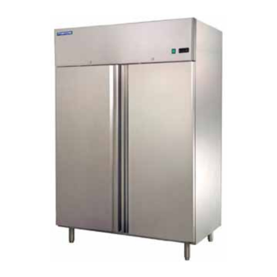
1.11.2102 Parts Name Construction Compressor Condenser Lock Hinge Front panel Control panel Light Shelf bracket Shelf 10. Door seal Door 12. Adjustable feet Lock Hinge Front panel Controller Shelf bracket Shelf Door seal Door Adjustable feet 4 Parts Name... -
Page 7: Adjusting The Temperature
1.11.2102 Adjusting the temperature UP / ON-OFF DOWN / MANUAL DEFROST Set point setting (desired temperature value) • press SET for 1 s, the set value will start flashing;. • increase or decrease the value using UP or DOWN. • press SET to confi rm the new value. -
Page 8: Cleaning And Maintenace
1.11.2102 Cleaning and maintenace Always disconnect the appliance from the mains before any cleaning and maintenance. The machine must not be cleaned with a pressure washer. Do not spray water direct on appliance. Avoid usin excess amounts of water. Water should not get in contact with electric components. -
Page 9: Installation Of Spring Hinge
1.11.2102 一.Spring hinge install Installation of spring hinge • Open the front panel (see fig) cover by removing the ST4×16 screw. • Remove the top hinge (1) by remo- ving the screws (2). Be careful, the spring is tuned. • Remove the hinge by lifting it up from the hole in the door. -
Page 10: Troubleshooting
1.11.2102 Troubleshooting In case of malfunction, review the following list to find out if it is possible to put the appliance in order without a service call. If the fault presists after making the mentioned checks, call service. PROBLEM POSSIBLE CAUSE ACTION The appliance does not start* •... -
Page 11: Technical Information
1.11.2102 Technical information Upright cabinet Model Voltage Freq Dimensions Volume Temperature Refri- Defrost (Hz) (L×D×h) gerated Power(W) weight Power(W) GNC660L1 220-240 50/60 R134a 660×750×2010 -2~10°C GNC740L1 220-240 50/60 R134a 740×870×2050 -2~10°C GNC1400L2 220-240 50/60 R134a 1400×870×2050 1200 -2~10°C GNF660L1 220-240... - Page 12 Refrigeration circuit diagram 1. Compressor 2. Condenser 3. Dryer 4. Capillary tube 5. Evaporator Refrigeration circuit diagram , models with remote cooling 1. Compressor 2. Condenser 3. Dryer 4. Valve 5. Evaporator 6. Remote cooling unit (not included in the delivery)
- Page 13 Circuit diagram GNC660L1...
- Page 14 Circuit diagram GNC740L1...
- Page 15 Circuit diagram GNF660L1...
- Page 16 Circuit diagram GNF740L1...
Need help?
Do you have a question about the GNC660L1 and is the answer not in the manual?
Questions and answers