Table of Contents
Advertisement
Company Website
Company WeChat
GOODWE (China)
189 Kunlunshan Rd, SND,
Suzhou, China
Tel: 400-998-1212 (after-sales service)
sales@goodwe.com.cn
service.chn@goodwe.com.cn
GOODWE (Netherlands)
Zevenwouden 194,
3524 CX Utrecht, the Netherlands
Tel: +31 6 1988 6498 (after-sales service)
sales@goodwe.com.cn
service.nl@goodwe.com.cn
Note: The above contact details are subject to change without notice. Please visit our company's
official website www.goodwe.com.cn for details.
GOODWE (Australia)
19 Faireleigh Street, VIC,
3046, Australia
Tel: +61 3 9324 0559 (after-sales service)
sales@goodwe.com.cn
service.au@goodwe.com.cn
GOODWE (United Kingdom)
46 Foyle Road London N17 0NL
United Kingdom
Tel: 44 (0)333 358 3184
enquiries@goodwe.co.uk
service@goodwe.co.uk
EzLogger Pro SERIES USER MANUAL
EzLogger Pro
Monitoring Data Logger
Advertisement
Table of Contents

Subscribe to Our Youtube Channel
Related Manuals for Goodwe EzLogger Pro SERIES


Summary of Contents for Goodwe EzLogger Pro SERIES
- Page 1 Company Website Company WeChat EzLogger Pro SERIES USER MANUAL GOODWE (China) GOODWE (Australia) 189 Kunlunshan Rd, SND, 19 Faireleigh Street, VIC, Suzhou, China 3046, Australia Tel: 400-998-1212 (after-sales service) Tel: +61 3 9324 0559 (after-sales service) sales@goodwe.com.cn sales@goodwe.com.cn service.chn@goodwe.com.cn service.au@goodwe.com.cn...
-
Page 2: Table Of Contents
Table of Contents Table of Contents Chapter I: Safety Precautions ..................... 1.1 Safety Instructions ......................1.2 Schematic Symbols ......................Chapter II: Product Introduction .................... 2.1 Product Introduction ....................... 2.2 Appearance Description ....................2.3 Description of LED Indicators ..................Chapter III: Equipment Installation .................. - Page 3 Table of Contents Chapter VII : Website Monitoring .................. 7.1 Register A New User and Add A Power Station............7.2 View Power Station Information ................Chapter VIII : Technical Specifications ................Chapter IX : Certification and Warranty ................9.1 Certification Mark ......................9.2 Warranty Period ........................
-
Page 4: Chapter I: Safety Precautions
1. Prevent children from approaching EzLogger Pro. 2. Do not open the upper cover, unauthorized touching or replacement of components may cause personal injury and damage to EzLogger Pro, in this case, GoodWe will not be liable for such injury or damage or quality warranty. -
Page 5: Chapter Ii: Product Introduction
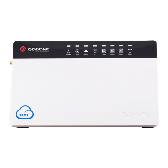
Chapter II: Product Introduction Chapter II: Product Introduction Introduce the appearance and function of EzLogger Pro. 2.1 Product Introduction Introduce the main functions of EzLogger Pro. EzLogger Pro is a dedicated device for the photovoltaic power generation system monitoring and management platform, which achieves interface aggregation, data acquisition, data storage, centralized monitoring, centralized maintenance and other functions for the inverters, environmental monitor, watt- hour meter and other devices in the photovoltaic power generation system. - Page 6 2.2 Appearance Description Front of the box L=190mm Figure 2.2-2 Front View of EzLogger Pro Box Side of the box Figure 2.2-3 Side View of EzLogger Pro Box Port Port Description Wi-Fi or GPRS antenna connector Sound alarm Buzzer sound hole Micro SD SD memory card slot USB slot...
- Page 7 2.2 Appearance Description Back of the box Figure 2.2-4 Back View of EzLogger Pro Box 1. Wall mounting hole 2. Rail clip 3. Cooling vents Top surface of the box Figure 2.2-5 Top View of EzLogger Pro Box 1. SIM card slot SIM card slot only can use in the EzLogger Pro with GPRS.
-
Page 8: Description Of Led Indicators
2.3 Description of LED Indicators Bottom surface of the box Figure 2.2-6 Bottom View of EzLogger Pro Box 2.3 Description of LED Indicators Introduce the meaning of the LED indicators. The LED indicators are as follows: Figure 2.3-1 Explanatory Drawing of LED Indicators... - Page 9 2.3 Description of LED Indicators Description of the LED indicators is as follows: Port Status Description Status Blue light On Power supply is normal POWER Blue light Off No power supply Blue light flashes (1s EzLogger Pro is running properly On/Off alternately) Blue light continue On or EzLogger Pro is not running properly...
-
Page 10: Chapter Iii: Equipment Installation
Chapter III: Equipment Installation Chapter III: Equipment Installation Introduce the packaging information and installation process of EzLogger Pro. 3.1 Packaging Information Introduce the packaged accessories of EzLogger Pro. After opening the EzLogger Pro package, please check whether the accessories are complete and there is any apparent damage. -
Page 11: Equipment Installation
3.2 Equipment Installation 3.2 Equipment Installation Introduction the installation process of EzLogger Pro. 3.2.1 Choose the installation location The following points shall be considered when you select the installation location: 1. The ingress protection rating of EzLogger Pro is IP20, so it has no waterproof performance and is for indoor use only. - Page 12 3.2 Equipment Installation 70mm Figure 3.2.2-1 Schematic Diagram of Wall Mounting of EzLogger Pro Installation method 3: Rail mounting Steps: 1. Drill two circular holes in the wall, the distance between the two circular holes is 100mm, the hole diameter is 8mm, and the hole depth is 40mm. =8mm D=40mm Figure 3.2.2-2 Schematic Diagram of Rail Mounting...
-
Page 13: Chapter Iv: Electrical Connection
Chapter IV: Electrical Connection Chapter IV: Electrical Connection Introduce how EzLogger Pro is electrically connected to the inverter, computer, environmental monitor, meter and other devices. 4.1 Port Description Introduce the ports of EzLogger Pro for connection with the inverters and their functions. -
Page 14: Connection To The Inverter
4.2 Connection to the Inverter 1. Below is the diagram of EzLogger Pro DI ports, where REF1 and REF2 occupy two ports respectively. Figure 4.1-2 Schematic Diagram of Ezlogger Pro DI Ports EzLogger Pro DI ports are compatible with RCR and DRED functions, and the ports for different functions are defined as follows: REF1 REF2... - Page 15 4.2 Connection to the Inverter COM ports are described as follows: Symbol Description Port RS485A, RS485 differential signal + COM1 RS485B, RS485 differential signal - RS485A, RS485 differential signal + COM2 RS485B, RS485 differential signal - RS485A, RS485 differential signal + COM3 RS485B, RS485 differential signal - Figure 4.2.1-2 Wiring Diagram of EzLogger Pro COM Ports...
-
Page 16: Connection To The Environmental Monitor And Meter
4.2.2 Connection to multiple inverters 4.2.2 Connection to multiple inverters Introduce how EzLogger Pro is connected to multiple inverters. When EzLogger Pro is connected to multiple inverters, “hand-in-hand” connection method can be used; each inverter has two multiplexed RS485 communication ports, and one RS485 port of the inverter is connected to one RS485 port of the next inverter. -
Page 17: Connection To The Computer
4.4 Connection to the Computer Description of COM4: Symbol Description Port RS485A, RS485 differential signal + COM4 RS485B, RS485 differential signal - Steps: 1. connect one end of the communication line to the RS485 port of the environment monitor and the meter. - Page 18 4.5 Connection to the Ripple Control Receiver The port is defined as follows: DI Port Description Active power derating Reactive power compensation EzLogger Pro is connected to the ripple control receiver as follows: Figure 4.5-2 Diagram of Connection of EzLogger Pro DI Port to RCR Steps: 1.
-
Page 19: Connection To Dred
4.6 Connection to DRED 4.6 Connection to DRED Introduce the function of DRED. According to the Australian safety regulations, power grid companies use DRED to convert power grid scheduling signals for dry contact transmission, and power stations need to use dry contact communication method to receive power grid scheduling signals. -
Page 20: Chapter : Lan Ezlogger Pro Data Upload And Function Configuration
Chapter V: EzLogger Pro Data Upload and Function Configuration Chapter : LAN EzLogger Pro Data Upload and Function Configuration Introduce LAN EzLogger Pro monitoring data transmission and the configuration method. 5.1 How to Use LAN EzLogger Pro Introduce LAN EzLogger Pro monitoring data transmission. After EzLogger Pro is connected to the collected data, one should connect EzLogger Pro to the Internet, so that EzLogger Pro can upload the collected data to the ser ver. -
Page 21: Ezlogger Pro Configuration
Firstly, the user needs to install “ProMate” software in the computer by downloading ProMate software from Internet (http://www.goodwe-power.com/files/ProMate. rar). Please access to the website to download the program and compete the installation. For connection of ProMate software to EzLogger Pro, the user needs to choose between dynamic IP (DHCP) and static IP, depending on the Internet configuration. - Page 22 5.2 EzLogger Pro Configuration 2. Configuration Method for EzLogger Pro Static IP Address: If the user has a static IP, it is necessar y to switch EzLogger Pro to the static IP mode. That is, press the Reload key for about 10 seconds to reset and restart EzLogger Pro, After restart, EzLogger Pro will be switched to static IP mode(default IP:192.168.1.200),then modify the computer ’...
- Page 23 5.2 EzLogger Pro Configuration (4) Pop up the local connection dialog box, right-click on “Local Connection” and then click on “Properties”. Figure 5.2-4 Modification of the Properties of Local Connections Pop up a dialog box as below: Figure 5.2-5 Modification of Internet Protocol 4 (TCP/IPv4)
- Page 24 5.2 EzLogger Pro Configuration (5) Double click on “Internet Protocol 4 (TCP/IPv4)” to pop up the “Properties” dialog box of “Internet Protocol 4 (TCP/IPv4)”, then complete the setting for the dialog box in accordance with the following requirements. The defaulted IP address for EzLogger Pro is 192.168.1.200. In order to put your computer and EzLogger Pro under the same network segment, you should set the IP address and the default gateway in 192.168.1.
- Page 25 5.2.1 Connecting ProMate to EzLogger Pro (6) Modification to the IP address of EzLogger Pro. The user can adopt the required configuration after connecting ProMate software to EzLogger Pro. In static IP mode, the user can configure IP address, subnet mask , gateway and DNS that can be accessed to Internet as required, as shown in Figure 5.2-8.
- Page 26 5.2.2 Quantity Configuration for Inverter Communication Port 5.2.2 Quantity Configuration for Inverter Communication Port Terminal configuration is used for setting EzLogger Pro ‘s COM1,COM2,COM3 ports which the quantity of inverters connecting,assume port 1(corresponding communication port COM1) connecting the quantity of inverters is 7,then check port 1,the quantity settings is 7,click on “Set”...
- Page 27 5.2.3 Time Setting 5.2.3 Time Setting Time setting will synchronize the time of EzLogger Pro and inverter and the time of synchronization server. Click on “Set Time” to pop up the following dialog box, as shown in the figure below. Then click on “OK”...
- Page 28 5.2.4 Field Debugging 5.2.4 Field Debugging ProMate can also be applied to field installation and debugging. After installation is completed, click on “Refresh” to show whether the inverter is online or not. If the system prompts “off line”, please check whether the connection cable has any problem, and then timely solve the problems till the system shows that all the inverter are “on line”.
- Page 29 5.2.5 DRED setting Figure 5.2-13 Enable DERD After start using successfully,the “ Refresh ” column will display. Figure 5.2-14 Real Time Data Meter power means: The electricity meter measure the grid power, display positive value means the user sell electricity power value, display negative value means the user buy electricity power value.
-
Page 30: Program Upgrade
5.2.6 RCR setting 5.2.6 RCR setting RCR function only apply to Germany.If the customer needs to start using RCR function,please set inverter ’s safety country first,then check “Enable” to enable RCR function.As picture 5.2-15. Figure 5.2-15 RCR Setting 5.3 Program Upgrade Introduction to local and remote upgrade method of EzLogger Pro. -
Page 31: How To Use Wi-Fi Ezlogger Pro
Chapter VI: Data Upload and Function Configuration For Wi-Fi EzLogger Pro (2) Remote Upgrade: Upgrade program is uploaded to the server by GOODWE in the background, so as to enable automatic check and update of EzLogger Pro. Chapter VI: Data Upload and Function Configuration For Wi-Fi EzLogger Pro Introduce the data transfer monitoring and configuration process of Wi-Fi EzLogger Pro Before reading Wi-Fi EzLogger Pro’s product manual, please install the antenna to ANT terminal first... -
Page 32: Using Promate To Configure Wi-Fi Ezlogger Pro
6.2 Using ProMate to configure Wi-Fi EzLogger Pro After Wi-Fi configuration success and EzLogger Pro connecting to router success,the “SERVER” LED on the EzLogger Pro will blink .After EzLogger Pro communicating with ser ver successfully,the “SERVER” LED will light.Once the Wi-Fi connecting is successful,Wi-Fi module will be the STA mode,that means EzLogger Pro cannot search out Wi-Fi hotspot.If the customer needs to reconfigure the Wi-Fi module connecting to router,it will have to long press the ”RELOAD”... -
Page 33: Chapter Vii : Website Monitoring
The following describes how to register and add power station information when the user logs on for the first time. Step 1: Open the browser, then visit http: //www.goodwe-power.com, and you can enter GOODWE monitoring platform homepage. Fill in the corresponding registration information, and click on “Register”... - Page 34 7.1 Register A New User and Add A Power Station Step 2: After user registration is completed, log on to enter the “Create/Edit Station” interface. Fill in each entry of “ station Information” field correctly according to the requirements, as shown in Figure 7.1-2. Figure 7.1-2 Create and Edit Power Station Step 3: Fill in “Maintain EzLogger Pro”...
- Page 35 7.1 Register A New User and Add A Power Station Then add the connected inverter under the corresponding EzLogger Pro, enter the inverter serial number (S/N) and check code, and click on the “Add” button. Inverter type and description shall be filled in by the user according to the actual situation.
-
Page 36: View Power Station Information
7.2 View Power Station Information 7.2 View Power Station Information After successful registration and completion of power station creation, you can log onto GOODWE monitoring platform to view power station information through the computer (Option I), iPhone, iPad or Android mobile devices (Option II). - Page 37 6.2 View Power Station Information For more detailed monitoring system operation method, please refer to the monitoring platform user manual, and the user can visit URL http://www.goodwe-power.com/, and click on “User Manual” to download. Figure 7.2-3 Smart Energy Management System User Manual Download Option II: The user can log on to view the information through mobile phone and other mobile devices.
- Page 38 7.2 View Power Station Information Take iPhone4s for example, and the relevant page is shown in Figure 7.2-5 after login: Figure 7.2-5 Mobile Phone Login Interface and List of Power Stations Step 2: Open the installed EzViewer to enter the login page, then enter your user name and password, and click on “Login”;...
-
Page 39: Chapter Viii : Technical Specifications
Chapter VIII : Technical Specifications Chapter VIII : Technical Specifications Introduce the technical indicators of EzLogger Pro. Communication management Inverter communication 3 x RS485 10/100M Ethernet Communication PC communication Wireless module (optional) Wi-Fi; GPRS Number of 60 (The number of devices connected to RS485 managed devices a single RS485 port shall not exceed 20) -
Page 40: Chapter Ix : Certification And Warranty
9.4 Warranty Conditions On the premise that the product is used according to GoodWe User Manual, if any product failure occurs within the warranty period due to quality problems, GoodWe provides the following three ways of warranty according to the actual circumstances: 1.
Need help?
Do you have a question about the EzLogger Pro SERIES and is the answer not in the manual?
Questions and answers