Table of Contents
Advertisement
Quick Links
Advertisement
Table of Contents

Subscribe to Our Youtube Channel
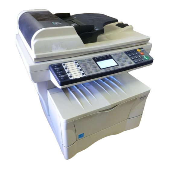
Summary of Contents for Copystar CS-1820
- Page 1 CS-1820 Includes: Fax System (K) SERVICE MANUAL Published in Mar ’05 2GM70940...
-
Page 2: Maintenance Mode
CONTENTS 1-1 Specifications 1-1-1 Specifications ............................1-1-1 1-1-2 Names of parts ............................. 1-1-3 (1) Main body ............................1-1-3 (2) Operation panel ..........................1-1-4 1-2 Handling Precautions 1-2-1 Drum ..............................1-2-1 1-2-2 Installation environment ........................1-2-1 1-3 Installation 1-3-1 Unpacking and installation ........................1-3-1 (1) Installation procedure ........................ -
Page 3: Assembly And Disassembly
(15) Fixing is poor..........................1-5-21 (16) Image center does not align with the original center..............1-5-21 1-5-4 Electrical problems ..........................1-5-22 (1) The machine does not operate when the power switch is turned on..........1-5-22 (2) The main motor does not operate. (C2000) ................. 1-5-22 (3) The scanner motor does not operate. -
Page 4: Upgrading The Firmware
1-6-13 Removing the exposure lamp ......................1-6-34 1-6-14 Removing the scanner mirror A ......................1-6-36 1-6-15 Removing the scanner motor ......................1-6-37 1-6-16 Removing the main charger unit ......................1-6-40 1-6-17 Adjustment the maintenance mode ....................1-6-41 (1) Adjusting the leading edge registration of image printing ............. 1-6-41 (2) Adjusting the center line of image printing .................. - Page 5 2-3-6 CCD PWB ............................2-3-22 2-3-7 Operation PWB ..........................2-3-24 2-3-8 Scanner PWB ............................. 2-3-26 2-4 Appendixes Timing chart No. 1 ............................2-4-1 Timing chart No. 2 ............................2-4-2 Timing chart No. 3 ............................2-4-3 Wiring diagram ............................... 2-4-4...
-
Page 6: Specifications
1-1-1 Specifications Type ..........Desktop Copying system ......Indirect electrostatic system " × 14" [legal]) Originals ......... Sheets of paper (Maximum original size: folio/8 Platen: Sheets of paper, books, 3-dimensional objects (Maximum original size: folio/ " × 14" [legal]) Original feed system ...... Contact glass: fixed Document processor (optional): sheet-through Copy paper ........ - Page 7 Power source ......... 120 V AC, 60 Hz, 7.8 A 220 - 240 V AC, 50/60 Hz, 4.0 A Power consumption ......854 W Options ........... Paper feeder, document processor (DP), additional memory and fax system • Printing functions " × 11": 18 prints/min. Printing speed ........
- Page 8 Problem Causes Check procedures/corrective measures Broken MP feed clutch Check for continuity across the coil. If none, replace the MP feed The MP feed clutch coil. clutch. does not operate. Poor contact in the MP Reinsert the connector. Also check for continuity within the con- feed clutch connector ter- nector cable.
- Page 9 Fax System (K) SERVICE MANUAL Published in July ’05 Revision 2...
- Page 10 CONTENTS 1-1 Specifications 1-1-1 Specifications ............................1-1-1 1-1-2 Parts names ............................1-1-4 (1) Main body ............................1-1-4 (2) Operation panel ..........................1-1-5 1-1-3 Mechanical construction ........................1-1-6 1-2 Installation 1-2-1 Unpacking and installation ........................1-2-1 (1) Unpacking and installation ......................1-2-1 1-3 Maintenance Mode 1-3-1 Maintenance mode ..........................
-
Page 11: Parts List
CS-1820 CS-1820LA Includes: Fax System (K) PARTS LIST Published in June ’05 2GM70950... - Page 12 CONTENTS FIG. 1 Exterior Covers ............2 FIG. 2 Frames & Paper Feed Section I .........4 FIG. 3 Paper Feed Section II & LSU ........6 FIG. 4 Driving Section ............8 FIG. 5 Process Unit..............10 FIG. 6 Fuser Unit ..............12 FIG. 7 Cassette ..............14 FIG.
- Page 13 FIG. 1 Exterior Covers - 2 -...
- Page 14 FAX System (K) PARTS LIST Published in March 2005 Version 1.0...


Need help?
Do you have a question about the CS-1820 and is the answer not in the manual?
Questions and answers