Table of Contents
Advertisement
Available languages
Available languages
Advertisement
Chapters
Table of Contents

Related Manuals for Ergon CF3


Summary of Contents for Ergon CF3
- Page 1 ERGON BIKE ERGONOMICS CF3 Pro Carbon Suspension VCLS Seatpost DE - Handbuch Montage und Anwendung Seite 3 EN - Installation and User Instructions Page 37 FR - Instructions d’installation et d’utilisation Page 71...
-
Page 3: Table Of Contents
ERGON BIKE ERGONOMICS Inhalt Inhalt der Verpackung Benötigtes Werkzeug Funktionsprinzip / Aufbau CF3 Wichtige Sicherheitshinweise Montage des Sattels Vor der Montage der Sattelstütze Einstellen der Sitzposition Einstellen der Sattelneigung Einstellen der Auszugslänge Befestigung im Rahmen Einstellen der horizontalen Sattel-Position Weitere Einstellungen der horizontalen Sattel-Position mittels Flip Head (Optional) Montage des Flip Heads für ovale Sattelgestelle... -
Page 4: Inhalt Der Verpackung
Inhalt der Verpackung A. CF3 Pro Carbon (Abb. A) oder CF3 Pro Carbon Setback (Abb. B), inkl. Flip Head Sattel-Außenklemmen 7x7 mm (Nur für runde Stahl- oder Titan- Sattelgestelle; für ovale Carbon-Sattelgestelle bitte Seite 22 beachten). Abb. A Abb. B oder B. -
Page 5: Benötigtes Werkzeug
ERGON BIKE ERGONOMICS Benötigtes Werkzeug A. Schleifpapier B. (Baumwoll-)Lappen C. Isopropanol (feine Körnung) Alkohol D. Drehmoment- E. Lineal (in mm) F. Wasserwaage schlüssel (Einheit Nm) -
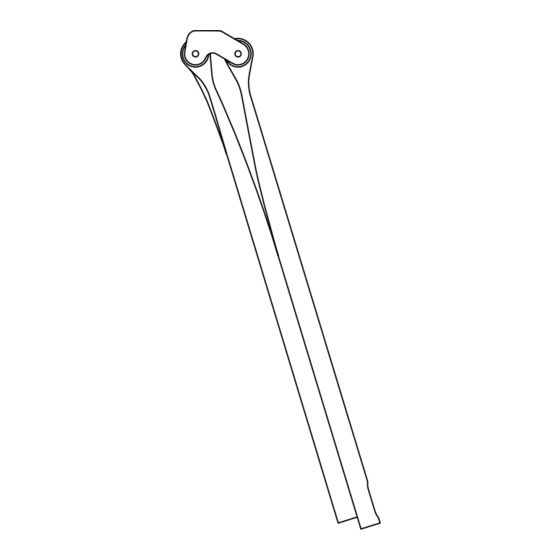
Page 6: Funktionsprinzip / Aufbau Cf3
Funktionsprinzip / Aufbau CF3 Die CF3 Sattelstütze besteht aus 2 parallel angeordneten Blattfedern. Die durch Fahrbahnunebenheiten erzeugten Stöße werden durch das Verschieben der Blattfedern nach hinten abgefedert. Die Blattfedern bestehen aus 19-lagigem Hochleistungsverbundwerkstoff. Das Ansprechverhalten ist sehr sensibel und aufgrund des physikalisch optimalen Konstruktionsprinzips ist die CF3 Stütze herkömmlichen Teleskop-Stützen deutlich überlegen. -
Page 7: Wichtige Sicherheitshinweise
ERGON BIKE ERGONOMICS Wichtige Sicherheitshinweise! Einsatzbereich: Die CF3 ist ausschließlich für den Einsatz auf Straßen-Renn- rädern bestimmt. Sie ist technisch ausgelegt und getestet für die Benutzung auf geteerten Straßen. Das Nichteinhalten der Warnhinweise dieser Beschreibung kann zum frühzeitigen Versagen der Sattelstütze und oder des Sattels und somit zu schweren Verletzungen bis hin zum Tode führen. - Page 8 Montage frei von Fett und Schmiermitteln sein. Beachten Sie hierzu die Hinweise auf den Seiten 12-13 dieser Montageanleitung. WARNUNG Die minimalen und maximalen Einstecktiefen sind auf der CF3-Sattel- stütze aufgedruckt - diese Werte sind unbedingt einzuhalten! Beachten Sie, dass der Fahrradhersteller eventuell eine längere Einstecktiefe als die minimal aufgedruckte vorschreibt.
- Page 9 • Sollte Ihre Sattelstütze knarren oder Knackgeräusche von sich geben oder äußerliche Schäden wie Kerben, Risse, Beulen, Verfärbungen etc. aufweisen, sollten Sie damit nicht mehr fahren. Wenden Sie sich an Ihren Ergon-Fachhändler und lassen Sie sie sorgfältig überprüfen und gegebenenfalls die Teile tauschen.
-
Page 10: Montage Des Sattels
Klemmen passen, z.B. weil es oval ist (Carbon-Gestell), wenden Sie auf keinen Fall Gewalt an. Für ovale Carbon-Sattelgestelle (7 x 9 mm) muss der optional erhältliche, wechselbare Ergon Flip Head Adapter für Carbon-Sattelge- stelle verwendet werden. Abb. A: Sattel-Klemmschrauben und Flip Head Abb. - Page 11 ERGON BIKE ERGONOMICS Drehen Sie die beiden Sattelklemmschrauben mit einem Drehmoment zwischen 4 und 5 Nm fest. Überschreiten Sie das maximale Drehmoment von 5 Nm nicht (Abb. D). Beachten Sie unbedingt die Hinweise zur Kompatibilität von Flip Head Sattel-Außenklemme zu verschiedenen Sattelgestellen auf Seite 23.
-
Page 12: Vor Der Montage Der Sattelstütze
Vor der Montage der Sattelstütze Lösen Sie die Arretierungsschraube am unteren Ende der Sattlelstütze und legen Sie diese mit der Unterlegscheibe zur Seite. Die beiden Blattfedern sind nun beweglich und am Sattelstütz-Kopf weiterhin arretiert. Öffnen Sie die Blattfedern v-förmig. Tragen Sie auf die gezeigten Flächen die mitgelieferte Carbon-Monta- gepaste dünn und gleichmäßig auf (zwischen den Blattfedern, sowie außen) (Abb. -
Page 13: Einstellen Der Sitzposition
Sie mit Isopropanol (Abb. B). Verwenden Sie keinesfalls scharfe Reinigungsmittel, z.B. Aceton. WARNUNG Achten Sie beim Putzen auf Risse, Kratzspuren, Materialverbiegungen oder -verfärbungen. Setzen Sie sich im Zweifelsfall mit Ihrem Ergon- Fachhändler in Verbindung. Lassen Sie beschädigte Bauteile umgehend ersetzen. ALC. - Page 14 Die Sattelstütze muss leichtgängig in Fahrtrichtung durch minimale Schwenkbe- wegungen in den Rahmen einzuführen sein (Abb. C). Drehen Sie die Schraube der Sattelstützen-Klemmschelle nur soweit an, dass die Stütze bei den weiteren Montageschritten nicht selbsttätig verrutscht (Abb. D). WARNUNG Das endgültige Festdrehen der Schrauben wird nach dem Einstellvor- gang bewerkstelligt.
-
Page 15: Einstellen Der Sattelneigung
ERGON BIKE ERGONOMICS Einstellen der Sattelneigung Mit einer waagerecht eingestellten bzw. leicht nach vorne abfallenden Sattelober- kante fahren die meisten Radfahrer am besten. Daher sollten Sie mit dieser Position starten. Die eingestellte Sattelneigung lässt sich an der Neigungsmarkie- rung an der Sattelstütze erkennen (Abb. A). - Page 16 Um die Sattelneigung zu fixieren, kontrollieren Sie die Sattelneigung (Neigungs- markierung). Passt diese, ziehen Sie die Stütze wieder heraus. Achten Sie darauf, dass sich die eingestellte Sattelneigung nicht verändert (Abb. C). Drehen Sie die Arretierungsschraube mit einem Drehmomentschlüssel und 6 bis 7 Nm fest.
-
Page 17: Einstellen Der Auszugslänge
Sattelstütze im Ganzen im Sitzrohr verschoben. Beachten Sie dabei die aufgedruckte Markierung der Mindest-Einstecktiefe (Sicherheitsweise auf Seite 8 beachten) (Abb. B). Bedenken Sie, die CF3-Sattelstütze federt beim Aufsitzen bereits ein kleines Stück ein. Addieren Sie für die erste Näherung daher pauschal 5 mm zur Sitzhöhe hinzu. -
Page 18: Befestigung Im Rahmen
Sattelstützenklemmschelle mit einem Drehmomentschlüssel und dem vom Rahmenhersteller vorgegebenen Drehmoment an. Überschreiten Sie jedoch das maximale Drehmoment der CF3-Sattelstütze von 7 Nm nicht (Abb. A). Falls Sie die Auszugslänge zu einem späteren Zeitpunkt nachjustieren möchten, beachten Sie unbedingt die Hinweise dieser Montageanleitung. -
Page 19: Einstellen Der Horizontalen Sattel-Position
ERGON BIKE ERGONOMICS Einstellen der horizontalen Sattel- Position Der Abstand zum Lenker wird zum einen wie gewohnt über das Verschieben des Sattels in der Sattelklemmung eingestellt. Lösen Sie die beiden Sattelklemm- schrauben um eine bis zwei Umdrehungen. Verschieben Sie den Sattel (Abb. A) und beachten Sie bei der Einstellung den typischerweise mit einer aufgedruckten Skala oder mit Stopp-Markierungen begrenzten Klemmbereich des Sattels. -
Page 20: Weitere Einstellungen Der Horizontalen Sattel-Position Mittels Flip Head
Weitere Einstellungen der horizon- talen Sattel-Position mittels Flip Head Um den Stellbereich durch den Flip Head zu verändern (Abb. C/D), entfernen Sie dafür die beiden Sattel-Klemmschrauben sowie den Sattel und montieren Sie alle vier Teile der Sattelklemmung jeweils paarweise auf der gegenüberlie- genden Seite (Abb. - Page 21 ERGON BIKE ERGONOMICS Back Front Back Front Abb. C: Diese Position ermöglicht einen Abb. D: Diese Position ermöglicht einen vergrößerten Stellbereich nach hinten (Abb. A). vergrößerten Stellbereich nach vorne (Abb. B).
-
Page 22: (Optional) Montage Des Flip Heads Für Ovale Sattelgestelle
Flip Head Sattel-Außenklemmen (7x9 mm) erworben haben, beachten Sie die folgenden Hinweise. Das Auswechseln der Flip Head-Außenklemmen ermöglicht es Ihnen Sättel mit ovalem 7x9 mm Sattelgestell auf der CF3 Sattelstütze zu montieren (die mitgelieferten Außenklemmen sind AUSSCHLIESSLICH für runde Sattelgestelle geeignet). Entfernen Sie die Klemmschrauben, die montierten Flip Head Außenklemmen (Abb. - Page 23 * Im Lieferumfang enhalten. Nur Sättel mit rundem Stahl- oder Titan-Gestell und einem Klemmmaß von 7x7 mm sind zur Montage freigegeben (Abb. C). ** Optional erhältlich. Kompatible Sättel: Ergon, Selle Italia, Fizik, Specialized. Nur Sättel mit ovalem Carbon-Gestell und einem Klemmmaß von 7x9 mm sind zur Montage freigegeben (Abb.
-
Page 24: Probefahrt
Probefahrt Nachdem Sie die CF3 Sattelstütze wie in der Montageanleitung beschrieben montiert haben, machen Sie eine vorsichtige Probefahrt auf Strecken mit lediglich leichten Unebenheiten. Überprüfen Sie, ob die Sattelstütze nicht nach unten verruscht. Zu stark angedrehte Schrauben, als Versuch die Durchmesserdifferenz auszugleichen, können zum Versagen des Sitzrohres, des Rahmens und/oder der Sattelstütze... -
Page 25: Toleranzausgleichs-Shim
ERGON BIKE ERGONOMICS Toleranzausgleichs-Shim WARNUNG Die Verwendung von Distanzhülsen (Shim) jeglicher Art ist ausdrücklich nicht freigegeben (außer beigelegtes Toleranzausgleich-Shim). Die Verwendung von Distanzhülsen kann zu einem Versagen der Sattelstütze und somit zu einem Unfall mit Verletzungsgefahr führen. Notieren Sie die bewährte Sattelneigung „a“ (Details siehe Seite 15) und die Auszugslänge „b“... - Page 26 Lösen Sie die Arretierungsschraube der Blattfedern und enfernen Sie diese mit der Unterlegscheibe (Abb. C). Säubern und bestreichen Sie die Blattfedern mit Carbon-Montagepaste (Details siehe Seite 12). Benetzen Sie außerdem das beigelegte Toleranzausgleichs-Shim auf der unbedruckten Seite mit etwas Carbon-Paste (Abb. D). Benutzen Sie hierzu die dem Toleranzausgleichs-Shim beiliegende Montagepaste, falls erforderlich.
- Page 27 ERGON BIKE ERGONOMICS Legen Sie das Toleranzausgleichs-Shim mit der unbedruckten Seite auf die Innenseite der hinteren Blattfeder (BACK) mit der Markierung mittig in den Bereich der notierten Sitzhöhe „b“ und drücken Sie es an. (Abb. E). Platzieren Sie die Unterlegsscheibe und Arretierungsschraube und ziehen Sie die Schraube mit 2 Umdrehungen an (Abb.
- Page 28 Stellen Sie die Sattelneigung „a“ gemäß Ihrer Notizen ein und ziehen Sie die Arretierungsschraube mit 6-7 Nm fest. Überschreiten Sie das Anzugsmoment von 7 Nm nicht (Abb. G). Das Toleranzausgleichs-Shim darf nicht verrutschen oder überstehen! Bauen Sie die Sattelstütze mit der notierten Auszugslänge „b“ ein und ziehen abschließend die Sattelklemmschraube mit dem vom Hersteller angegebenen Anzugsmoment fest.
-
Page 29: Pflege Und Wartung
ERGON BIKE ERGONOMICS Pflege und Wartung Reinigen Sie Ihre CF3-Sattelstütze regelmäßig mit Wasser und einem weichen Lappen. Falls notwendig, benutzen Sie eine Seife ohne schleifende Partikel um Schmutz zu entfernen. Bei hartnäckigen Verschmutzungen wie Öl oder Fett auf festen Oberflächen können Sie etwas handelsübliches Spülmittel in warmes Wasser geben. -
Page 30: Tipp: Sattelneigung
Tipp: Sattelneigung Vor der Montage der CF3 Sattelstütze empfehlen wir Ihre bewährte Sattel-Ein- stellung (im Bezug auf Sattelneigung, Auszugslänge und horizontale Sattel-Positi- on) zu notieren und auf die CF3 Sattelstütze zu übertragen. Der Sattel sollte grundsätzlich waagerecht stehen. Damit wird verhindert, dass man nach vorne oder hinten rutscht. -
Page 31: Tipp: Auszugslänge
ERGON BIKE ERGONOMICS Tipp: Auszugslänge Die Sitzhöhe ist das wichtigste Maß für effizientes Pedalieren und komfortables Sitzen. Die größte Kraft kann mit einer langen Beinstreckung übertragen werden. Zudem unterstützt eine große Sitzhöhe eine Beckenaufrichtung und damit eine gesunde Grundhaltung. Die Einstellung erfolgt nach einer einfachen Methode. Dazu wird die Schrittlänge (ohne Schuhe) ausgemessen (Abb. -
Page 32: Tipp: Horizontale Sattel-Position
Tipp: Horizontale Sattel-Position Der Nachsitz (horizontale Sattel-Position) ist der Abstand des Lots der Sattelspitze zu der Senkrechten der Tretlagerachse. In den meisten Fällen sollte die Sattelspitze etwas hinter der Senkrechten der Tretlagerachse liegen. Ein Standardmaß dafür sind etwa fünf Zentimeter. Je größer eine Person ist, desto weiter sollte der Sattel nach hinten gestellt werden (bis zu zehn Zentimeter). - Page 33 ERGON BIKE ERGONOMICS Auch hier gibt es eine Methode, nach der Montage der Sattelstütze die individuell beste Position zu ermitteln / zu prüfen. Dazu sitzt der Fahrer auf dem Rad in Fahrstellung. Die Kurbeln sind waagerecht ausgerichtet. Ein von der Kniescheibe gefälltes Lot sollte durch die Pedalachse gehen (Abb.
-
Page 34: Sachmängelhaftung
Sachmängelhaftung Während der ersten zwei Jahre nach dem Kauf der CF3-Sattelstütze haben Sie vollen Anspruch auf die gesetzliche Sachmängelhaftung (vormals Gewähr- leistung). Sollten Mängel auftreten, wenden Sie sich bitte unter Vorlage des Kaufbelegs an Ihren Ergon-Fachhändler. Detailliertere Informationen zur Sachmängelhaftung / Reklamation finden Sie online unter www.ergonbike.com/warranty oder einfach QR-Code scannen. - Page 35 ERGON BIKE ERGONOMICS...
- Page 37 ERGON BIKE ERGONOMICS Table of Contents Package Contents Tools required The CF3 explained Important safety information Attaching the saddle Before installation of the seatpost Adjusting the saddle position Adjusting the angle of the saddle Adjusting the seatpost extension Fastening in the frame...
-
Page 38: Package Contents
Package Contents A. CF3 Pro Carbon (Fig. A) or CF3 Pro Carbon Setback (Fig. B), including Flip- Head saddle outer clamps for 7x7 mm rails (only for round steel or titanium rails; for oval carbon rails please see page 56). -
Page 39: Tools Required
ERGON BIKE ERGONOMICS Tools required A. Emery paper B. Clean rag C. Isopropyl alcohol (fine-grain) Alcohol D. Torque wrench with E. Ruler/tape measure F. Spirit level Nm readings (in mm) -
Page 40: The Cf3 Explained
The CF3 explained A CF3 seatpost is comprised of two leaf springs arranged in parallel. Unevenness in the road surface causes small impacts which the leaf springs absorb by flexing backwards. The leaf springs are made up of 19 layers of high performance composite. -
Page 41: Important Safety Information
ERGON BIKE ERGONOMICS Important safety information Recommended Use: The CF3 is exclusively designed for use on road bicycles. Use of the seatpost on any type of mountain bike is strictly prohibited. The technical specification and testing has been carried out with use intended on paved roads. - Page 42 For more information, refer to pages 46-47 of these instructions. The minimum and maximum insertion for the post are printed on the CF3 seat post. These must be strictly adhered to. Please note, that the frame manufacturer may require the seatpost to be inserted further than our minimum marking.
- Page 43 • If your seat post creaks or makes cracking or squeaking noises or if external damage such as notches, cracks, dents, or discoloration, etc., can be seen, then you should not use it any longer. Contact your Ergon dealer and have it checked carefully and replace the parts if necessary.
-
Page 44: Attaching The Saddle
If this is not the case, for example with oval rails (carbon rails), never force it. For oval carbon rails (7x9 mm) the separately available Ergon Flip Head Adapter for Carbon Saddle Rails must be used. - Page 45 ERGON BIKE ERGONOMICS Tighten the clamp using torque of between 4 and 5 Nm. Never exceed the maximum torque of 5 Nm (Fig. D) or the saddle manufactures recommendations. Pay particular attention to the information about the compatibility of the Flip Head Saddle Clamp with different rails on page 57.
-
Page 46: Before Installation Of The Seatpost
– the leaf springs should be able to slide against each other (Fig. B). Fig. A: Remove the lock screw and washer. Fig. B: Replace the lock screw and washer. Apply Ergon or Dynamic carbon paste. Tighten with 2 turns. -
Page 47: Adjusting The Saddle Position
Use alcohol to remove any stubborn residues of grease (Fig. B). Never use aggressive cleaners such as acetone. While cleaning, look for cracks and scratches, as well as bent or discolored material. If in doubt, contact your Ergon dealer. Have any damaged parts replaced at once. Alcohol Fig. - Page 48 Insert the seatpost into the frame. The back of the post is clearly marked “Back”. Try to minimize twisting as you fit the seat post (Fig. C). Tighten the seatpost clamp just enough so that the seatpost does not slide into the frame during the remaining setup steps.
-
Page 49: Adjusting The Angle Of The Saddle
ERGON BIKE ERGONOMICS Adjusting the angle of the saddle Most cyclists find it best to have the saddle set horizontally or inclined slightly downwards at the front. Please use the seat angle you had with your old post. The angle of inclination of the saddle that has been set can be seen on the angle of inclination “ruler”... - Page 50 Ensure that Carbon Assembly Paste is applied between the leaf springs. The CF3 seat post may not be used without the lock screw. Apply a tightening torque of 6-7 Nm.
-
Page 51: Adjusting The Seatpost Extension
(see warnings on page 8) (Fig. B). Bear in mind that the CF3 seat post already provides a small amount of springiness when it is sat on. For that reason add a total of 5 mm to the seat height for the first approximation. -
Page 52: Fastening In The Frame
Do not exceed the maximum tightening torque of 7 Nm for the CF3 seat post regardless of the frame makers torque (Fig. A). If you need to adjust the seatpost extension at a future date, please ensure that you follow the instructions in this manual. -
Page 53: Adjusting The Horizontal (Fore/Aft) Position Of The Saddle
Fasten the saddle clamp screws using 4 - 5 Nm. (Fig. B). For tips on adjusting the horizontal position of the saddle, see page 66. The CF3 also allows an increase in the adjustment range by turning the entire Flip Head saddle clamp unit. The following instructions (on pages 54-55) must be followed when using this method. -
Page 54: Adjustment Of The Horizontal Position Of The Saddle By Flipping Flip Head
Further adjustment of the horizontal position of the saddle by flipping Flip Head In order to change the horizontal adjustment range using the Flip Head (Fig. C/D), loosen and remove the clamping screws, the external clamp, the saddle and the internal clamp, and re-install all four parts to the opposite side of the seatpost (Fig. - Page 55 ERGON BIKE ERGONOMICS Back Front Back Front Fig. C: This position allows the saddle to be Fig. D: This position allows the saddle to be moved further back (Fig. A). moved more foreword (Fig. B).
-
Page 56: (Optional) Fitting Of Oval Saddle Rail Clamps To Flip Head
(Optional) Fitting of oval saddle rail clamps to Flip Head If you have a saddle with oval rails and purchased the oval rail Flip Head saddle clamps please review this section. Removal and replacement of the Flip Head saddle clamp will allow the users to fit a saddle with oval 7x9mm rails (the standard clamp is for round rails ONLY). - Page 57 ERGON BIKE ERGONOMICS Pay attention to the compatibility of the Flip Head outer clamp and the saddle rails used. Flip Head Saddle Rail Shape Material 7x7 mm* 7x7 mm round Steel or Titanium 7x9 mm** 7x9 mm oval Carbon * Included with the seat post. Only suitable for use with round steel or titanium rails measuring 7x7 mm (Fig.
-
Page 58: Test Ride
Test ride After you have fitted your CF3 seat post according the instructions, it is time for a short careful test ride on smooth pavement with little traffic or other hazards. Make sure that the seatpost does not slip into the frame. Do not over tighten the clamp to compensate. -
Page 59: Anti-Slip Shim
ERGON BIKE ERGONOMICS Anti-Slip Shim Do not use any other seatpost shims other than the one provided with the post, and only one such shim may be used. Any other type of shim may cause a failure of the post and an injury. - Page 60 Undo and remove the lock screw and washer. (Fig. C). Clean and recoat the CF3 Pro Carbon’s two leaf springs with carbon paste (see details on page 46). Coat the supplied Anti-Slip Shim with a little carbon paste on the unprinted side.
- Page 61 ERGON BIKE ERGONOMICS Fit the anti-slip shim unprinted side down onto the inner side of the rear leaf spring (the one marked BACK). The marking on the anti-slip shim should be level with the noted saddle height ‘b’ so that the shim is about in the middle of the binder bolt clamping area when the post is placed back in the bike at the correct height.
- Page 62 Do not clamp the Ergon CF3 using more than 7 Nm torque (Fig. H). If the seat post still slips when you sit on it even with the use of the Ergon shim then the post will not work on your frame. max.
-
Page 63: Care And Maintenance
ERGON BIKE ERGONOMICS Care and maintenance Regularly clean your CF3 seat post using water and a soft cloth. If required, use a soap without any abrasive particles to remove the dirt. If this involves stubborn dirt such as oil or grease on the fixed surfaces, then you can use a little ordinary liquid dish detergent washing up liquid in warm water. -
Page 64: Tip: Angle Of The Saddle
Tip: Angle of the saddle We recommend using the previous saddle position you had (in terms of tilt, height and fore aft (horizontal) position) before installing the CF3 seatpost. Generally speaking a saddle should be level. This prevents the rider slipping forwards or backwards. -
Page 65: Tip: Seatpost Extension
ERGON BIKE ERGONOMICS Tip: Seatpost extension For efficiency on the bike, the saddle height is the most important measurement. Greatest power transfer occurs when the leg is almost completely straight. Additionally the correct saddle height allows for the pelvis to be positioned in a way which makes sitting comfortable. -
Page 66: Tip: Horizontal Position Of The Saddle
Tip: Horizontal position of the saddle The fore / aft adjustment (horizontal saddle position) is the distance of the tip of the nose of the saddle in relation to the bottom bracket axle (Fig. A). Usually this is behind the bottom bracket axle - around 5 cm. The taller the person is, the further behind this line the tip of the saddle will be - up to 10 cm. - Page 67 ERGON BIKE ERGONOMICS Making this adjustment can also be done according to set methods. The rider sits on the bike in the riding position. The cranks should be horizontal, The fore / aft adjustment should be make until the knee cap of whichever leg is the leading leg is directly over the pedal axle (Fig.
-
Page 68: Ergon Worldwide Limited Warranty
Ergon worldwide limited warranty Ergon warrants to the original retail purchaser that this product is free from defects in material and workmanship for (2) two years from the date of original retail purchase. Please see the current full warranty policy at www.ergonbike.com/warranty or scan QR-code for details. - Page 69 ERGON BIKE ERGONOMICS...
- Page 71 (Option) Montage de brides de rail de selle ovales sur le chariot Flip Head Parcours de test Compensateur de Tolérance-Shim Entretien et maintenance Conseil: Inclinaison de la selle Conseil: Longueur d’extraction de la tige de selle Conseil: Position horizontale de la selle Garantie mondiale limitée de Ergon...
-
Page 72: Contenu De L'emballage
Contenu de l’emballage A. CF3 Pro Carbon (Fig. A) ou CF3 Pro Carbon Setback (Fig. B), avec brides de selle extérieures Flip Head pour rails de 7x7 mm rails (seulement pour rails ronds en acier ou en titane; pour des rails en carbone ovales, voir la page 90). -
Page 73: Outils Nécessaires
ERGON BIKE ERGONOMICS Outils nécessaires A. Toile émeri B. Chiffon propre C. Alcool isopropylique (grain fin) Alcool D. Clé dynamométrique E. Règle / mètre ruban F. Niveau à bulle avec indications de Nm (en mm) -
Page 74: Le Cf3 Expliqué
Le CF3 expliqué La fixation de selle CF3 se compose de deux ressorts parallèles à lames spécialement conçus. Lors de chocs créés par une chaussée inégale, ceux-ci seront amortis par le déplacement vers l’arrière des ressorts à lames. Les ressorts à lames sont constitués d’un matériau composite à haute résistance en 19 couches. -
Page 75: Remarques Relatives À La Sécurité
ERGON BIKE ERGONOMICS Remarques relatives à la sécurité Usage recommandé : la CF3 est conçue exclusivement pour être montée sur des vélos de route. L’emploi de la tige de selle sur n’importe quel type de vélo VTT est formellement interdit. Les spécifications techniques et les essais ont été... - Page 76 à un accident. Pour de plus amples informations, consultez la page 81 des présentes instructions. La pâte pour carbone Ergon (fournie) ou la pâte pour carbone Dynamic doit être utilisée sur la tige de selle entre les lames en carbone et dans le tube de selle du cadre afin d’éviter tout glissement.
- Page 77 UTILISEZ TOUJOURS UNE CLÉ DYNAMOMÉTRIQUE POUR LE MONTAGE. La fixation CF3 Pro Carbon n’est conçue que pour des supports de selle ronds (7 x 7 mm, en acier ou en titane). Pour les supports de selle carbone ovales (7 x 9 mm), il convient d’employer l’adaptateur disponible...
-
Page 78: Montage De La Selle
(rails en carbone), ne forcez jamais. Pour des rails en carbone ovales (7 x 9 mm), il convient d’employer l’adaptateur Ergon Flip Head Adapter pour rails de selle en carbone qui est disponible séparément. - Page 79 ERGON BIKE ERGONOMICS Serrez les deux vis de blocage de la selle avec un couple de serrage compris entre 4 et 5 Nm. Ne dépassez jamais le couple maximum de 5 Nm (Fig. D) ou les recommandations du fabricant de la selle. Veillez tout particulièrement aux informations relatives à...
-
Page 80: Prémontage De La Tige De Selle
à lames doivent rester mobiles l’un par rapport à l’autre. Fig. A: Déposez la vis de blocage et la rondelle. Fig. B: Reposez la vis de blocage et la rondelle. Appliquez de la pâte pour carbone Ergon. Serrez en effectuant 2 tours. -
Page 81: Réglage De La Position De La Selle
AVERTISSEMENT Profitez du nettoyage pour repérer les fissures, les traces d’éraflures, les déformations de matériel ou les altérations de couleur. En cas de doute, contactez votre revendeur Ergon. Faites remplacer immédiatement les composants endommagés. Alcool Fig. A: Éliminez les bavures éventuelles du tube Fig. - Page 82 La tige de selle doit être introduite dans le cadre dans le sens de la marche, avec de légers mouvements rotatifs. (Fig. C). Serrez la vis du collier de serrage de la tige de selle juste assez pour que la tige ne puisse se décaler d’elle-même pendant les étapes de montage qui suivent (Fig.
-
Page 83: Réglage De L'inclinaison De La Selle
ERGON BIKE ERGONOMICS Réglage de l’inclinaison de la selle La plupart des cyclistes roulent de préférence avec une selle dont la lisière supérieure est réglée en position horizontale ou légèrement inclinée vers l’avant. Aussi vous est-il conseillé de tester d’abord ces positions. La plage d’inclinaison portée sur la tige de selle permet de vérifier l’inclinaison de la selle (Fig. - Page 84 AVERTISSEMENT Appliquez de la pâte de montage pour carbone entre les ressorts à lames. La tige de selle CF3 ne doit pas être utilisée sans la vis d’arrêt. Respectez le couple de serrage de 6 à 7 Nm. Tournez le moins...
-
Page 85: Réglage De La Hauteur De La Tige De Selle
ERGON BIKE ERGONOMICS Réglage de la longueur d’extraction Enfoncez la tige de selle CF3 dans le tube de selle du cadre avec de légers mouvements rotatifs (Fig. A). Reportez votre hauteur de selle habituelle au moyen d’un mètre pliant sur la nouvelle tige. Pendant cette opération, tenez compte du repère gravé... -
Page 86: Fixation Au Cadre
Cependant, ne dépassez pas le couple de serrage maximum de 7 Nm prescrit pour la tige de selle CF3 (Fig. A). Si vous devez modifier la longueur d’extraction de la tige de selle ultérieurement, veillez à... -
Page 87: Réglage De La Position Horizontale (Avant/Arrière) De La Selle
Resserrez les vis avec une intensité de 4 à 5 Nm (Fig. B). Conseils pour l’installation de la position horizontale page 100. La CF3 permet aussi d’augmenter la plage de réglage en tournant l’unité de bride de selle Flip Head complète. Les instructions ci-dessous (aux pages 88-89) doivent être respectées lorsque cette méthode est appliquée. -
Page 88: Réglage De La Position Horizontale De La Selle Via Le Chariot Flip Head
Réglage de la position horizontale de la selle via le chariot Flip Head Pour modifier la plage de réglage horizontal à l’aide du chariot Flip Head (Fig. C/D), desserrez et déposez les vis de serrage, la bride extérieure, la selle et la bride intérieure, puis réinstallez les quatre éléments du côté... - Page 89 ERGON BIKE ERGONOMICS Back Front Back Front Fig. C: Cette position permet de reculer un peu Fig. D: Cette position permet d‘avancer un peu plus la selle (fig. A). plus la selle (fig. B).
-
Page 90: (Option) Montage De Brides De Rail De Selle Ovales Sur Le Chariot Flip Head
(Option) Montage de brides de rail de selle ovales sur le chariot Flip Head Si vous possédez une selle à rails ovales et que vous avez acheté les brides de selle Flip Head pour rails ovales, veuillez lire cette section. En déposant et en remplaçant la bride de selle Flip Head, vous pourrez monter une selle à... - Page 91 ERGON BIKE ERGONOMICS Veillez à la compatibilité de la bride extérieure Flip Head avec les rails de selle utilisés. Flip Head Rail de selle Forme Matière 7x7 mm* 7x7 mm ronde Acier ou titane 7x9 mm** 7x9 mm ovale Carbone * Inclus avec la tige de selle.
-
Page 92: Parcours De Test
Parcours de test Après avoir monté votre tige de selle CF3 selon les instructions, il est temps de procéder à un court essai prudent sur une route à revêtement lisse peu fréquentée ou peu risquée. Vérifiez que la fixation de selle ne se déplace pas vers le bas. Quelques dixièmes de millimètre en trop dans le dimensionnement interne de la tige de selle peut... -
Page 93: Compensateur De Tolérance-Shim
ERGON BIKE ERGONOMICS Compensateur de Tolérance-Shim AVERTISSEMENT N’utilisez pas de compensateurs pour tige de selle autres que ceux fournis avec la tige, et seulement un compensateur de ce type peut être utilisé. Tout autre type de compensateur peut provoquer une défaillance de la tige et une blessure. - Page 94 Desserrer la vis d’arrêt du ressort à lames, et l’éloigner avec la rondelle. (Fig. C). Nettoyez et recouvrez les deux ressorts à lames de la CF3 Pro Carbon de pâte pour carbone (voir la page 80 pour de plus amples détails). Enduire le côté...
- Page 95 ERGON BIKE ERGONOMICS Placer le côté non-appuyé du compensateur de tolérance-Shim sur la partie interne de l’arrière du ressort à lames (BACK), le mettre en place avec la marque dans la zone de la hauteur de siège notée «b», et appuyer. (Fig. E). Mettre en place la vis d’arrêt, et la serrer légèrement (2 ou 3 tours) (Fig.
- Page 96 «b», et serrer le blocage de selle avec l’intensité de couple de serrage indiquée par le fabricant. Ne serrez pas l’Ergon CF3 à un couple supérieur à 7 Nm (Fig. H). Si la tige de selle glisse toujours lorsque vous vous asseyez dessus, même en utilisant le compensateur de tolérance, cela signifie...
-
Page 97: Entretien Et Maintenance
Contrôlez le serrage des vis de votre tige de selle CF3 au bout de 100 à 300 kilomètres ou après 4 à 12 heures d’utilisation, puis tous les 2000... -
Page 98: Conseil: Inclinaison De La Selle
Nous vous recommandons d‘utiliser la position de votre selle précédente (en termes d‘inclinaison, de hauteur et de position avant / arrière (horizontale)) avant d‘installer la tige de selle CF3. De façon générale, la selle devrait être horizontale par rapport au sol. Cet angle empêche le cycliste de glisser vers l’avant ou vers l’arrière et aide aussi à... -
Page 99: Conseil: Longueur D'extraction De La Tige De Selle
ERGON BIKE ERGONOMICS Conseil: Longueur d’extraction Lorsqu’il est question d’efficacité pour un vélo, la hauteur de selle constitue la mesure la plus importante. Le transfert de puissance le plus important se produit lorsque la jambe est presque entièrement droite. De plus, une hauteur de selle optimale place le bassin de telle sorte que la position assise est confortable. -
Page 100: Conseil: Position Horizontale De La Selle
Conseil: Réglage du recul Le recul de selle correspond à la distance de la pointe du bec de selle par rapport à l’axe de pédalier (Fig. A). La mesure moyenne se situe habituellement à 5 cm derrière l’axe de pédalier. Cependant, plus le cycliste est grand, plus la selle recule derrière l’axe de pédalier (jusqu’à... - Page 101 ERGON BIKE ERGONOMICS Ce réglage peut aussi être effectué selon d’autres méthodes. Par exemple, le cycliste, qui est assis sur la selle, place son pied sur la pédale (cette dernière doit être horizontale). Dans ce cas-ci, le recul de selle est correct lorsque la rotule de la jambe est située directement au-dessus de l’axe de la pédale (Fig.
-
Page 102: Garantie Mondiale Limitée De Ergon
Garantie mondiale limitée de Ergon Ergon garantit à l‘acheteur de détail original que le présent produit est exempt de défauts de matière et de fabrication pendant une période de (2) deux ans à compter de la date d‘achat initiale. Veuillez consulter la politique de garantie complète en vigueur sur www.ergonbike.com/warranty ou scanner votre code QR pour de plus amples... - Page 103 ERGON BIKE ERGONOMICS...
- Page 104 Ergon USA: 8285 Sunset Blvd. Suite #12 West Hollywood, CA. 90046 T 323-848-4665, T 877-573-7466, F 323-848-9097 www.ergon-bike.com Ergon is a worldwide trademark. Ergon reserve the right to change any products without prior ® notice. Druckfehler, Irrtümer und Änderungen vorbehalten. ERG_MAN_CF3_05_2014...
Need help?
Do you have a question about the CF3 and is the answer not in the manual?
Questions and answers