
Related Manuals for Coleman OUTFITTER 700-L


Summary of Contents for Coleman OUTFITTER 700-L
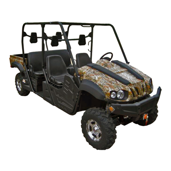
- Page 1 OWNER’S MANUAL POWERSPORTS OUTFITTER 700-L No one under the age of 16 should operate this UTV (888)-405-8725 Coleman Powersports 2010 E University Drive , Suite 15, Tempe, AZ. 85281...
- Page 2 Congratulations on your purchase of a Coleman UTV. This Owner’s/Operator’s manual will provide you information regarding safe operation, operational instructions, maintenance and care. Fully understanding this manual and following all of the instructions herein will provide the knowledge needed to have safe and enjoyable UTV operation.
- Page 3 Owner 's Manual...
- Page 4 Owner 's Manual IMPORTANT MANUAL INFORMATION FAILURE TO FOLLOW THE WARNINGS CONTAINED IN THIS MANUAL CAN RESULT IN SERIOUS INJURY Particularly important information is distinguished in this manual by the following OR DEATH. notations: The Safety Alert Symbol means ATTENTION! YOUR SAFETY IS INVOLVED! Failure to follow WARNING instructions could result in severe injury or death to the machine operator, bystander or a person inspecting or repairing the...
- Page 5 This manual is based on the latest product information available at the time of publication. Coleman Powersports has a policy of continually improving its products. Due to improvements, or other changes, there may be some discrepancies. We reserve the right to make product changes at any time, without notice and without incurring any obligation to make the same or similar changes to vehicles previously built or sold.
- Page 6 Owner 's Manual IMPORTANT NOTICE Curve speed must be slower than 19 mph ( 30km/h ). This UTV is designed and manufactured for OFF - ROAD use only. It is illegal and unsafe to operate this UTV on any public street, road or highway. This UTV complies with all applicable OFF - ROAD noise level and spark arrester laws and regulations in effect at the time of manufacture.
-
Page 7: Table Of Contents
Owner 's Manual Coleman Limited Warranty Location of the Warning and Switches Specification Labels Accelerator Pedal 4-13 Brake Pedal 4-14 Safety Information Parking Brake Lever 4-15 Drive Select Lever 4-16 Description and Vehicle Fuel Tank Cap 4-16 Identification Front Seats... - Page 8 Owner 's Manual Pre Operation Checks Lights 5-10 Brakes Switches 5-10 Brake Pedal Tires 5-11 Brake Fluid Level How to Measure Tire Pressure 5-12 Brake Fluid Leakage Tire Wear Limit 5-13 Brake Operation Operation Fuel Starting the Engine in Low Gasohol Temperatures Engine Oil...
- Page 9 Owner 's Manual Driving Your Vehicle General Maintenance and Lubrication Chart Getting to Know Your Vehicle Hood Learning to Operate Your Vehicle Console Turning your Vehicle Engine Oil and Oil Filter Cartridge Braking To Check the Engine Oil Level Going Uphill To Change the Engine Oil 8-10 Going Downhill...
- Page 10 Owner 's Manual Valve Clearance 8-29 Replacing Headlight Bulb 8-45 Front Brake Pad Check 8-29 Headlight Beam Adjustment 8-48 Rear Brake Pad Check 8-30 Tail/brake Light Bulb Replacement 8-48 Checking the Brake Fluid Level Troubleshooting 8-31 8-50 Brake Fluid Replacement 8-32 Solution to Common Problems in Checking the Brake Pedal...
- Page 11 During this period of time, Coleman Powersports, will, at its option, either repair or replace any original Coleman part which is covered by this warranty and is proven to be defective in workmanship or material.
- Page 12 Length of Implied Warranties Any implied warranties are limited to the duration set forth in this warranty. Coleman Powersports does not make any claim as to the merchantability or fitness for a particular purpose which would extend longer than the duration of this written warranty.
- Page 13 Location of the Warning and Safety Labels...
- Page 14 Location of the Warning and Safety Labels Read and understand all of the labels on your vehicle. They contain important information for safe and proper operation of your vehicle. Never remove any labels from your vehicle. If a label becomes difficult to read or comes off, a replacement label is available from your dealer.
- Page 15 Location of the Warning and Safety Labels...
- Page 16 Location of the Warning and Safety Labels...
- Page 17 Location of the Warning and Safety Labels...
- Page 18 Location of the Warning and Safety Labels...
-
Page 19: Safety Information
Safety Information SAFETY INFORMATION This off-highway utility vehicle handles differently from other vehicles including cars and UTVs. SEVERE INJURY OR DEATH can result if you do not follow these instructions: Read this manual and all labels carefully and follow the operating procedures described. ●... - Page 20 Safety Information Never attempt jumps or other stunts. ● Always inspect your vehicle each time you use it to be sure it is in safe operating condition, ● Always follow the inspection and maintenance procedures and schedules described in this manual.
- Page 21 Safety Information Never operate the vehicle on hills that are too steep for it or for your abilities. Go straight up and down ● hills where possible. Maximum slope angle: 15°. Never operate on hills that are slippery or ones where you will not be able to see far enough ahead of ●...
- Page 22 Safety Information WARNING POTENTIAL HAZARD Improper handling of gasoline. WHAT CAN HAPPEN Gasoline can catch fire and you could be burned. HOW TO AVOID THE HAZARD Always turn off the engine when refueling. Do not refuel right after the engine has been running and is still very hot.
- Page 23 Safety Information WARNING POTENTIAL HAZARD Starting or running the engine in a closed area. WHAT CAN HAPPEN Exhaust fumes are poisonous and may cause loss of consciousness and death within a short time. HOW TO AVOID THE HAZARD Always operate your vehicle in an area with adequate ventilation.
- Page 24 Description and Vehicle Identification Headlights Cargo bed Front shock absorber assembly adjusting ring Tail/brake lights Brake fluid reservoir Spark arrester Air filter element(engine and air intake duct) Fuel tank cap Spark plug Passenger seat V-belt case Oil filter cartridge Driver seat belt Engine oil dipstick Driver seat Battery...
- Page 25 Description and Vehicle Identification 23. Light switch Steering wheel Brake pedal Main switch On-Command four-wheel-drive and differential lock switches Multi-function meter unit Auxiliary DC jack Drive select lever Parking brake lever Accelerator pedal NOTE: The vehicle you have purchased may differ slightly from those in the figures of this manual.
-
Page 26: Identification Number Records
Description and Vehicle Identification Identification Number Records Vehicle identification number Record the key identification number, vehicle The Vehicle identification number is stamped identification number model label into the frame. information in spaces provided for assistance when ordering spare parts from a service center or for reference in case the vehicle is stolen. -
Page 27: Control Functions
Control Functions Functions of the respective switch positions CONTROL FUNCTIONS are as follows: Main switch All electrical circuits are supplied with power, and the headlights and taillights illuminate when the light switch is on. OFF: All electrical circuits are switched off. The key can be removed in this position. -
Page 28: Indicator And Warning Lights
Control Functions CAUTION: Indicator and warning lights Do not operate the electric starter ● continuously for more than 5 seconds at a time, or starter damage could occur. Wait at least 5 seconds between each start attempt. Do not turn the key to the ―START‖ ●... - Page 29 Control Functions ―DIFF. LOCK‖ Low-range indicator light “L” This indicator light comes on when the drive On-Command differential gear lock indic- select lever is in the ―L‖ position. ator light “DIFF. LOCK” High-range indicator light “H” This indicator light and the On-Command This indicator light comes on when the drive differential gear lock indicator in the display select lever is in the ―H‖...
- Page 30 Control Functions NOTE: drive indicator also comes on when the If the indicator light flashes under any other On-Command differential gear lock switch is set to the ―LOCK‖ position. circumstances or the speedometer does not show the speed while riding, have a dealer NOTE: check the speed sensor circuit.
-
Page 31: Multi-Function Meter Unit
Control Functions engine as soon as it is safe to do so and Multi-Function Display Gauge allow the engine to cool down for about 15 minutes. CAUTION: The engine may overheat if the vehicle is overloaded. If this happens, reduce the load to recommended specification. -
Page 32: Odometer And Trip Meter Modes
Control Functions speed) To reset a trip meter, select it by pushing the Odometer (which shows the total distance ―TRIP/ODO‖ button, and then push the ―TRIP/ODO‖ button for at least three seconds. traveled) Two trip meters (which show the distance The trip meters can be used to estimate the traveled since they were last set to zero) distance that can be traveled with a full tank... -
Page 33: To Set The Clock
Control Functions CLOCK→HOUR→CLOCK See attachment for faults code ( page 11-1-11-3) To Set the Clock 1. Set into the clock mode. When the fault code is confirmed and has 2. Press the watch button for 3-5 seconds. been repaired, you just need to press the 3. -
Page 34: Switches
Control Functions Switches 1. Fuel level warning indicator 2. Fuel meter 1. Light switch ―OFF/ ‖ Light switch “OFF/ ” Set the switch to ― ‖to turn on the low beam and the taillights. Set the switch to ― ‖to turn on the high beam and the taillights. - Page 35 Control Functions On-Command four-wheel –drive and diff- CAUTION: erential gear lock switches Do not use the headlights with the engine turned off for an extended period of time. The battery may discharge to the point that the starter motor will not operate properly. If this should happen, remove the battery and recharge it.
- Page 36 4-10 Control Functions plied to the rear wheels only. WARNING Four-wheel drive (―4WD’): Power is POTENTIAL HAZARD supplied to the rear and front wheels. Changing from 2WD to 4WD or from Four–wheel drive with the differential 4WD to 4WD-LOCK (“DIFF.LOCK”), or gear locked (―4WD-LOCK‖): Power is vice-versa while the vehicle is moving .
- Page 37 Control Functions 4-11 the select lever is set to position On-Command four-wheel-drive switch then set the switch to ―2WD‖. “2WD/4WD” On-Command differential gear lock switch “4WD”/”LOCK” 1. Select lever 2. On-Command four –wheel-drive switch ―2WD/4WD‖ To change from 2WD to 4WD ,stop the vehicle, then switch...
- Page 38 4-12 Control Functions the select lever to position ,and then set the switch to ―LOCK‖. When the differential WARNING gear is locked, the differential gear lock POTENTIAL HAZARD indicator light (―DIFF. LOCK‖) will come on Riding too fast while the vehicle is in along with the differential gear lock indicator 4WD-LOCK.
-
Page 39: Accelerator Pedal
Control Functions 4-13 NOTE: se engine speed. Spring pressure returns the When the switch is set to ―LOCK‖, the pedal to the rest position when released. differential gear lock indicator Always check that the accelerator pedal indicator light will flash until returns normally before staring the engine. -
Page 40: Brake Pedal
4-14 Control Functions Brake pedal WARNING POTENTIAL HAZARD Malfunction of the accelerator pedal. WHAT CAN HAPPEN A faulty pedal that makes it difficult to speed up or slow down could cause loss of control. HOW TO AVOID THE HAZARD Check the operation of the accelerator 1. -
Page 41: Parking Brake Lever
Control Functions 4-15 Parking brake lever The parking brake lever is located at the right side of the driver’s seat. It will help hold the vehicle from moving while parked. To set the parking brake, pull the lever up completely. To release the parking brake, pull up on the lever, press the release button, and then push the lever all the way down. -
Page 42: Drive Select Lever
4-16 Control Functions Drive select lever Fuel tank cap The drive select lever is used to shift you Remove the fuel tank cap by turning it vehicle into the low, high, neutral and reverse counterclockwise. positions. (Refer to pages 6-4—6-6 for the drive select lever operation.) 1. -
Page 43: Front Seats
Control Functions 4-17 To install a seat, insert the projection on the Front Seats rear of the seat into the seat holders and To remove a seat, pull its seat lock lever push down on the seat at the front. upward, lift the front of the seat, and then WARNING slide the seat forward and up. -
Page 44: Rear Seats
4-18 Control Functions Rear Seats 1. Rear seat To remove the rear seats, you need to pull it up from back, and then push it back. -
Page 45: Seat Belt For Front Seats
Control Functions 4-19 Seat Belt For Front Seats Seat Belt For Rear Seats This vehicle is equipped with three-point seat belts for both the operator and passenger. Always wear the seat belt while riding in the vehicle. 1. Driver seat 2. - Page 46 4-20 Control Functions following: 3. Put the lap portion of the belt low on your 1. Hold the latch plate as you pull the belt hips. Push down on the buckle end of the across your lap and chest. Make sure the belt as you pull up on the shoulder part belt is not twisted and is not caught on so the belt is snug across your hips.
- Page 47 Control Functions 4-21 WARNING POTENTIAL HAZARD Not wearing the seat belt. Wearing the seat belt improperly. WHAT CAN HAPPEN There is increased risk of being killed or seriously injured in an accident. HOW TO AVOID THE HAZARD 1. Buckle 2. Release button Always wear your seat belt when riding in the vehicle.
-
Page 48: Glove Compartment
4-22 Control Functions Glove compartment Cargo bed CAUTION: To protect from damage, do not put metal products, like tools sharply edged products directly in the glove compartment. If they must be stored, wrap them in appropria- te cushion material. 1. Cargo bed 2. -
Page 49: Opening And Closing The Tailgate
Control Functions 4-23 Opening and closing the tailgate Lifting and lowering the cargo bed 1. Tailgate 2. Latch (×2) 1. Cargo bed release lever To open To lift Push down the cargo bed release lever on Unhook the latches, and then lower the the left or right side of the vehicle, and then tailgate. - Page 50 4-24 Control Functions WARNING Maximum load limit: 150kg (330lb) POTENTIAL HAZARD Overloading the cargo bed WARNING WHAT CAN HAPPEN POTENTIAL HAZARD Could cause changes in vehicle handl- Pinch points. ing which could lead to an accident. WHAT CAN HAPPEN HOW TO AVOID THE HAZARD You or someone else could be pinched Never exceed the stated maximum load between the cargo bed and the frame...
-
Page 51: Front And Rear Shock Absorber Adjustment
Control Functions 4-25 Front and rear shock absorber adjustment The spring preload can be adjusted to suit WARNING the operating conditions. POTENTIAL HAZARD You can reduce preload for a softer ride, or Carrying a passenger in the cargo bed increase preload if frequent bottoming out of WHAT CAN HAPPEN The passenger could fall, be thrown the UTV occurs. - Page 52 4-26 Control Functions Standard position: B A-Minimum(soft) E-Maximum(hard) 1. Spring preload adjusting ring 2. Position indicator NOTE: A special wrench can be obtained at a dealer 1. Special wrench to make this adjustment.
-
Page 53: Trailer Hitch Bracket
Control Functions 4-27 Trailer hitch bracket This vehicle is equipped with a 1 ¼ in WARNING receiver bracket for a standard trailer hitch. POTENTIAL HAZARD Trailer towing equipment can be obtained at Improper shock absorber adjustment. a dealer. (See pages 6-12-6-14 for precaut- WHAT CAN HAPPEN Uneven adjustment can cause poor ion information.) -
Page 54: Auxiliary Dc Jack
4-28 Control Functions insert the accessory power plug into the Auxiliary DC jack jack. The auxiliary DC jack is located at the right side of the front panel. The auxiliary DC jack can be used for suitable work lights, radios, etc. The auxiliary DC jack should only be used when the engine is running. - Page 55 Control Functions 4-29 4. When the auxiliary DC jack is not being used, cover it with the cap. CAUTION: Do not use accessories requiring more than the above maximum capacity. This may overload the circuit and cause the fuse to blow. ...
-
Page 56: Pre Operation Checks
Pre Operation Checks Before using this vehicle, check the following points: ITEM ROUTINE PAGE Check operation, free play, fluid level and fluid leakage. ● Brakes 5-2—5-3,8-32 Fill with DOT 4 brake fluid if necessary. ● Check for proper operation, condition and free play. ●... -
Page 57: Brakes
Pre Operation Checks Brakes Brake pedal WARNING Check for correct brake pedal free play. If the POTENTIAL HAZARD brake pedal free play is incorrect, have a Failure to inspect the vehicle before dealer adjust it. (See pages 8-34-8-35.) operating. Failure to properly maintain the vehicle. -
Page 58: Brake Fluid Leakage
Pre Operation Checks WARNING Recommended brake fluid: DOT 4 POTENTIAL HAZARD Driving with improperly operating Brake fluid leakage brakes. Check to see if any brake fluid is leaking out WHAT CAN HAPPEN of the pipe joints or the brake fluid reservoir. You could lose braking ability, which Apply the brakes firmly for one minute. - Page 59 Pre Operation Checks octane number ([R+M] /2) of 91 or higher, or Fuel Make sure there is sufficient gasoline in the research octane number of 91 or hither. If tank. knocking or pinging occurs, use a different brand of gasoline or premium unleaded fuel. Recommended fuel: Unleaded fuel will give you longer spark plug Unleaded gasoline only...
-
Page 60: Engine Oil
Pre Operation Checks Engine oil Make sure the engine oil is at the specified WARNING level. Add oil as necessary. (See pages POTENTIAL HAZARD 8-10 .) Improper care when refueling. WHAT CAN HAPPEN CAUTION: Fuel can spill, which can cause a fire ... -
Page 61: Coolant
Pre Operation Checks CAUTION: Recommended engine oil type and Hard water or salt water is harmful to the quantity: engine. You may use soft water if you cannot See page 10-2 get distilled water. Coolant Coolant reservoir capacity Check the coolant level in the coolant (up to the maximum level mark): reservoir when the engine is cold. -
Page 62: Final Gear Oil
Pre Operation Checks WARNING Recommended oil: POTENTIAL HAZARD SAE 80 API GL-4 Hypoid gear oil Removing the radiator cap when the If desired, an SAE 80W90 hypoid gear oil engine and radiator are still hot. may be used for all conditions. WHAT CAN HAPPEN NOTE: You could be burned by hot fluid and... -
Page 63: Throttle Pedal
Pre Operation Checks Throttle Pedal WARNING Check to see that the accelerator pedal Failure to check or maintain proper operates correctly. It must operate smoothly operation of the throttle system can and fully spring back to the idle position result in an accident and lead to when released. -
Page 64: Throttle Freeplay Inspection
Pre Operation Checks Throttle Freeplay Inspection 1. Lift the parking brake to the top to park the car. 2. Apply the brakes. Start the engine. Allow it to warm up thoroughly. 3. Measure the distance the throttle pedal moves before the engine begins to pick up speed. -
Page 65: Seat Belts
Pre Operation Checks 5-10 2. Lightly turn the steering wheel left and Have a service center repair as necessary right. for proper operation. 3. There should be 0.8″-1.0″ (20-25 mm) of freeplay. Fittings and fasteners If there is excessive freeplay or strange Always check the tightness of chassis fittings noises, or the steering feels rough or ″... -
Page 66: Tires
5-11 Pre Operation Checks Tires 2. The tires should be set to the WARNING recommended pressure: POTENTIAL HAZARD ● Recommended tire pressure Operating this vehicle with improper Front 10psi (70kpa, 0.7 kgf/cm tires, or with improper or uneven tire Rear 10psi (70kpa, 0.7 kgf/cm pressure. -
Page 67: How To Measure Tire Pressure
Pre Operation Checks 5-12 Set tire pressures to the following specifica- tions: Front 36psi (250kpa, 2.5kgf/cm Rear 36psi (250kpa, 2.5kgf/cm Recommended Minimum Maximum Higher pressures may cause the tire to Pressure burst. Inflate the tires very slowly and 10psi (70kpa 9 psi (63kpa, 11 psi, (77kpa, Front... -
Page 68: Tire Wear Limit
5-13 Pre Operation Checks Tire wear limit When the tire groove decreases to 0.12 in (3 mm) due to wear, replace the tire. a. Tire wear limit... -
Page 69: Operation
Operation Starting The Engine In Low Temperatures WARNING WARNING POTENTIAL HAZARD POTENTIAL HAZARD Operating vehicle without being Freezing control cables cold familiar with all controls. weather. WHAT CAN HAPPEN WHAT CAN HAPPEN Loss of control, which could cause an You could be unable to control the accident or injury. -
Page 70: Starting The Engine
Operation Starting The Engine NOTE: When the drive select lever is in the ● CAUTION: neutral position“N”, the neutral indicator See the “Engine Break-In”section prior to light should come on. If the neutral operating the engine for the first time. indicator light does not come on, ask a service center to inspect the electric circuit. - Page 71 Operation NOTE: If the engine fails to start, release the key, WARNING and then try starting again. Wait a few POTENTIAL HAZARD seconds before the next attempt. Each Engine idle speed exceeds cranking should be as short as possible to regulated speed.
-
Page 72: Warming Up
Operation Warming Up Drive Select Lever Operation And Driving To get maximum engine life, always warm up In Reverse the engine before driving. Never accelerate hard with a cold engine! To see whether or CAUTION: not the engine is warm, check if it responds Before shifting, you must stop the UTV and to the throttle normally . - Page 73 Operation accelerator pedal. NOTE: 2. Apply the brake pedal. Make sure that the drive select lever is 3. Shift from neutral to reverse or vice versa completely shifted into position. by moving the drive select lever along the shift guide. NOTE: Please kick the brake pedal first, before ●...
- Page 74 Operation NOTE: When in reverse, the reverse indicator ● light should be on. If the light does not come on, ask a dealer to inspect the reverse indicator light electrical circuit. Due to the synchronizing mechanism in ● the engine, the light may not come on until the vehicle starts moving.
-
Page 75: Parking
Operation WARNING POTENTIAL HAZARD Improperly operating in reverse. WHAT CAN HAPPEN You could hit an obstacle or person behind you, resulting in serious injury. HOW TO AVOID THE HAZARD When you shift into reverse, make sure there are no obstacles or people 1.Parking handbar behind you. -
Page 76: Parking On A Slope
Operation Parking On a Slope WARNING POTENTIAL HAZARD Parking on a hill or other incline. WHAT CAN HAPPEN The vehicle could roll out of control, increasing the chance of an accident. HOW TO AVOID THE HAZARD Avoid parking on hills or other inclines. -
Page 77: Vehicle Break-In Period
Operation NOTE: Like many other vehicles, the parking brake acts on the rear wheels. For the parking Excessive heat build-up during the first ● brake to operate all four wheels, shift to 4WD three hours of operation will damage before stopping the engine. close-fitted engine parts... - Page 78 6-10 Operation not put an excessive load on it for the first 0-10 Hours: several hours of running. Avoid continuous operation above half During the first 25 hours, the various parts in throttle. Allow a cooling off period of five to the engine wear and polish themselves to the ten minutes after every hour of operation.
-
Page 79: Accessories
Operation 6-11 braking when the brake system is new could operating a vehicle which has accessories. damage brake pads and rotors. Choose only accessories designed for ● your vehicle. Your dealer has a variety of CVT Break-in (Clutches/Belt) genuine accessories. Other accessories A proper break-in of the clutches and drive may also be available on the market. -
Page 80: Loading
6-12 Operation the vehicle. Examples include (but are MAXIMUM LOADING LIMIT not limited to) an object that limits your Vehicle loading limit (total weight of ● ability to turn the steering wheel or one cargo, operator, passengers and that limits your view. accessories, and tongue weight): Use extra caution when driving a vehicle ●... - Page 81 Operation 6-13 with a bathroom scale. Put the tongue of you are going. the loaded trailer on the scale with the Drive more slowly than would without a ● tongue at hitch height. Adjust the load in load. The more weight you carry, the the trailer, if necessary, to reduce the slower should...
- Page 82 6-14 Operation WARNING POTENTIAL HAZARD Overloading this vehicle or carrying or towing cargo improperly. WHAT CAN HAPPEN Could cause changes vehicle handling which could lead to an accident. HOW TO AVOID THE HAZARD Never exceed the stated load capacity for this vehicle. Cargo should be properly distributed and securely attached.
-
Page 83: Driving Your Vehicle
Your Vehicle DRIVING YOUR VEHICLE WARNING GETTING TO KNOW YOUR VEHICLE POTENTIAL HAZARD This off-highway utility vehicle will handle Not wearing the seat belt. and maneuver differently form an ordinary Wearing the seat belt improperly. passenger car or other vehicle. WHAT CAN HAPPEN Before you begin to use your vehicle, be sure There is increased risk of being killed or... - Page 84 Your Vehicle The total weight of operator, passenger, accessories, cargo, trailer tongue weight, WARNING and the vehicle itself must not exceed 1880 POTENTIAL HAZARD lbs (853Kg). Carrying a passenger in the cargo bed. WHAT CAN HAPPEN The passenger could fall or be struck by objects in the cargo bed.
- Page 85 Your Vehicle The driver and passenger must always wear a seat belt and an approved motorcycle WARNING helmet. Also wear eye protection and POTENTIAL HAZARD protective clothing, including over-the-ankle Overloading this vehicle or carrying or towing cargo improperly. boots, gloves, a long-sleeved shirt or jacket, WHAT CAN HAPPEN and long pants.
- Page 86 Your Vehicle WARNING HOW TO AVOID THE HAZARD POTENTIAL HAZARD Always wear an approved motorcycle Operating this vehicle without wearing an helmet that fits properly. You should also approved motorcycle helmet, protection, and protective clothing. wear: WHAT CAN HAPPEN eye protection Operating without approved...
-
Page 87: Learning To Operate Your Vehicle
Your Vehicle LEARNING TO OPERATE YOUR VEHICLE 5-1-5-11. Set the parking brake, shift to should become familiar with neutral, and follow the instructions on page performance characteristics of the vehicle in 6-1 to start the engine. Once it has warmed a large, flat area that is free of obstacles and up and you have turned the choke off, you other vehicles. -
Page 88: Turning Your Vehicle
Your Vehicle 1CAUTION: Position your hands on the steering wheel so Do not shift from low to high or vice versa that your thumbs and fingers do not wrap without coming to a complete stop and around the wheel. This is particularly important waiting for the engine to return to normal idle when driving in rough terrain. -
Page 89: Braking
Your Vehicle Operating Improperly in Reverse slowly. Improperly operating in reverse could result in a collision with an obstacle or person. Always follow proper operating procedures 。 Follow these precautions when operating in reverse: 1. Always check for obstacles or people behind the vehicle. -
Page 90: Going Uphill
Your Vehicle surfaces. GOING UPHILL Do not attempt to climb hills until you have mastered basic maneuvers on flat ground. Use proper driving techniques to avoid overturns on hills and slopes. Drive straight up hills, and avoid crossing the side of a hill, which increases your chance of rollover. - Page 91 Your Vehicle Before climbing the hill, first be sure you are WARNING operating in low range 4WD or, if necessary, POTENTIAL HAZARD with 4WD Diff. Lock. To climb a hill, you need Operating on excessively steep hills. traction, momentum, and steady throttle. WHAT CAN HAPPEN Travel fast enough to keep your momentum The vehicle can over turn more easily on...
-
Page 92: Going Downhill
7-10 Your Vehicle behind you and plan your descent. Shift the appear. drive select lever in reverse so you can use WARNING the engine brake if necessary to slow your POTENTIAL HAZARD descent. Release the brake and begin to Going down a hill improperly. coast down the hill. -
Page 93: Crossing Through Shallow Water
Your Vehicle 7-11 Before starting down hill, make sure the CROSSING THROUGH SHALLOW WATER vehicle is in low-range 4WD. On most slopes, If you must cross shallow, slow moving water this will let you use engine braking to help up to the depth of the vehicle’s floorboards, you go downhill slowly. -
Page 94: Vehicle Immersion
7-12 Your Vehicle 1CAUTION: WARNING After riding your vehicle in water, be sure to POTENTIAL HAZARD drain the trapped water by removing the Operating this vehicle through deep or check hose at the bottom of the air filter case, fast-flowing water. the V-belt cooling duct check hose, the drive WHAT CAN HAPPEN select lever box check hose and the V-belt... - Page 95 Your Vehicle 7-13 you succeed in starting it or not. your service center before starting the 8. If water has been ingested into the CVT, engine. make sure inspect the hole without water If it’s impossible to take your vehicle to a left inside.
- Page 96 7-14 Your Vehicle 1.Air filter case check hose 1. Drive select lever box check hose 1.V-belt cooling duct check hose 1.V-belt case drain plug...
-
Page 97: Riding Over Rough Terrain
Your Vehicle 7-15 RIDING OVER ROUGH TERRAIN Operating over rough terrain should be done with caution. Look for obstacles that could cause damage to the vehicle or could lead to a rollover accident. Avoid jumping the vehicle as injury, loss of control, and damage to the vehicle could occur. -
Page 98: Encountering Obstacles On The Trail
7-16 Your Vehicle vehicle tipping . Go only fast enough to for brush that might enter the vehicle as you maintain your momentum but still give pass and strike the driver or passenger. yourself plenty of time to react to changes in Never hold onto the enclosure so your hand conditions.... - Page 99 Your Vehicle 7-17 WARNING POTENTIAL HAZARD Improperly operating over obstacles. WHAT CAN HAPPEN Could cause loss of control or a collision. Could cause the vehicle to overturn. HOW TO AVOID THE HAZARD Before operating in a new area, check for obstacles.
-
Page 106: Hood
① on the underside of the hood into slots ② on the back of the instrument panel. Secure slots ③ on the side of the hood around projections ④ on the frame. -
Page 107: Console
1. Remove the seats. (See pages 4-17─ 4-18 for seat removal and installation procedures.) 2. Remove the parking brake lever boot. 3. Pull the console upward (the drive select lever boot will come loose.) 1. Projection (×2) 2. Slot (×2) 3. - Page 108 periodic maintenance and lubrication chart. 1. Place the console in its original position. 2. Install the parking brake lever boot. 1. Place the vehicle on a level surface. 3. Install the seats. 2. Remove the console. (See page 8-8 for console removal installation...
- Page 109 8. Install the console. The engine oil should be between the minimum and maximum level marks. 1. Remove the console. (See page 8-8 for console removal installation procedures.) 2. Place an oil pan under the engine to collect the used oil, and then remove the engine oil filler cap.
- Page 110 1. Engine oil drain bolt 1. Oil filter cartridge 2. Oil filter wrench Skip steps 4-6 if the oil filter cartridge is not An oil filter wrench is available at a nearby being replaced. service center. 5. Apply a light coat of engine oil to the 4.
- Page 111 1. O-ring 1. Oil filler cartridge 2. Torque wrench 6. Install the new oil filter cartridge with an 7. Install the engine oil drain bolt, and then oil filter wrench, and then tighten it to the tighten it to the specified torque. specified torque with a torque wrench.
- Page 112 engine oil filler cap and tighten it. the crankcase. Recommended engine oil: 9. Start the engine, and then let it idle for See page 10-2. several minutes while checking it for oil Oil quantity: leakage. If oil is leaking, immediately turn Without oil filter cartridge replacement: the engine off and check for the cause.
-
Page 113: Final Gear Oil
1. Be sure no foreign material enters the final gear case. 2. Please clean the sensor every 500km period 4. Install the oil filler bolt, and then tighten it to the specified torque. Tightening torque: Final gear oil filler bolt: 1. - Page 114 Recommended oil: SAE 80 API GL-4Hypoid gear oil Oil quantity: 0.25 L (0.22 lmp qt, 0.26 US qt) Be sure no foreign material enters the final gear case. 1. Final gear oil drain bolt 6. Install the oil filler bolt, and then tighten it 4.
-
Page 115: Differential Gear Oil
Be sure no foreign material enters the 1. Place the vehicle on a level surface. differential gear case. 2. Remove the differential gear oil filler bolt 3. Install the differential gear oil filler bolt, and check the oil level. It should be up to and then tighten it to the specified the brim of the filler hole. - Page 116 Recommended oil: SAE 80 API GL-5 Hypoid gear oil Oil quantity: 0.32 L (0.28 lmp qt, 0.34 US qt) Be sure no foreign material enters the differential gear case. 6. Install the differential gear oil filler bolt, 1. Differential gear oil drain bolt and then tighten it to the specified 4.
-
Page 117: Coolant
The coolant level should be checked before each ride. 1. Place the vehicle on a level surface. 2. Open the hood. (See pages 8-7 8-8 for hood opening and closing procedures.) 3. Check the coolant level in the coolant reservoir when the engine is cold as the coolant level varies... - Page 118 possible. Coolant reservoir capacity radiator automatically (up to the maximum level mark): switched on or off according to the 0.35L (0.31 lmp qt, 0.37 US qt) coolant temperature in the radiator. Mix anti freeze with distilled water only. However, if distilled water is not available, Check the protective boots for holes or soft water may be used for refilling.
-
Page 119: Axle Boots
1. Lift the cargo bed up. (See pages 4-22 for cargo bed lifting and lowering procedures.) 2. Remove the spark plug cap. 1. Front axle boot (×2 each side) 1. Spark plug cap 3. Use the spark plug wrench in the tool kit to remove the spark plug as shown. - Page 120 Do not attempt to diagnose such problems yourself. Instead, take the vehicle to a service center. You should periodically remove and inspect the spark plug because heat and deposits will cause the spark plug to slowly break down and erode. If electrode erosion becomes excessive, or if carbon and other deposits are excessive, you should replace the spark plug with the specified plug.
- Page 121 If a torque wrench is not available when you are installing the spark plug, a good estimate of the correct torque is 1/4 to 1/2 turn past finger tight. Have the spark plug tightened to the specified torque as soon as possible. 4.
- Page 122 1. Air filter check hose 1. Holder (×4) 2. Air filter case cover Remove the seats. (See pages 4-17─ 4. Remove the air filter element. 4-18 for seat removal and installation 5. Remove the sponge material from its procedures. ) frame.
- Page 123 6. Wash the sponge material gently but thoroughly in solvent. 1. Air filter element Squeeze the excess solvent out of the sponge material and let it dry. Do not twist the sponge material when squeezing it. 8. Inspect the sponge material and replace 1.
- Page 124 it if damaged. 9. Thoroughly apply foam air filter oil or other quality liquid foam air filter oil (not spray type) to the sponge material. The sponge material should be wet but not dripping. 10. Pull the sponge material over its frame. 11.
- Page 125 performed, check the air inlet to the air filter case for obstructions. Check the air filter The V-belt cooling duct check hose is element rubber joint to the carburetor and located under the driver seat.(See pages manifold fittings securely to avoid the 4-17 ─...
- Page 126 The V-belt case drain plug is located under the driver seat.(See pages 4-17 ─ 4-18 for seat removal and installation procedures.) After riding in water deep enough to allow water to enter the V-belt case, remove the drain plug to drain any water from the case. If water drains from the V-belt case after removing the drain plug, have a service 1.
- Page 127 1. Bolt(×3) 1. Tailpipe 2. Spark arrester 1. Remove the tailpipe by pulling it out of 4. Insert the tailpipe into the muffler and the muffler. align the bolt holes. 2. Tap the tailpipe lightly, and then use a 5. Install the tailpipe by installing the bolts, wire brush to remove any carbon and then tighten the bolts to the specified deposits from the spark arrester portion...
- Page 128 The correct valve clearance changes with use, resulting in improper fuel-air supply or engine noise. To prevent this, the valve clearance must be adjusted regularly. This adjustment however, should be left to a professional service technician. Each brake pad is provided with wear indicator grooves, which allow you to check the brake pad wear without having to disassemble the brake.
- Page 129 Each brake pad is provided with wear indicator grooves, which allow you to check the brake pad wear without having to disassemble the brake. To check the brake pad wear, check the wear indicator grooves. If a brake pad has worn to the point that the wear indicator grooves...
- Page 130 and the brake system for leakage. The brake fluid reservoir is located under the hood. (See pages 8-7 for hood opening and closing procedures.) Observe these precautions: When checking the fluid level, make sure the top of the brake fluid reservoir is level.
- Page 131 the fluid and may result in vapor lock. Brake fluid may deteriorate painted Have a service center check the brakes at surfaces or plastic parts. Always clean the intervals specified in the periodic up spilled fluid immediately. maintenance and lubrication chart. There Have a service center inspect the brake should be no free play in the brake pedal.
- Page 132 Periodically check the parking brake lever free play and adjust it if necessary. 1. Shift the drive select lever into low gear 2. Remove the seats. (See page 4-17— 4-18 for seat removal and installation procedures.) 3. Remove the console. (See page 8-8 for console removal installation...
- Page 133 1. Locknut 2. Adjusting nut 1. Parking brake lever free play 6. Turn the adjusting nut in direction increase the free play or in direction The parking brake lever must be released to decrease the free play. when checking and adjusting the parking 7.
- Page 134 The brake light switch, which is activated by the brake pedal, is properly adjusted when the brake light comes on just before braking takes effect. If necessary, adjust the brake light switch as follows. 1. Open the hood. (See pages 8-7 for hood opening and closing procedures.) 2.
- Page 135 Lubricate the pivoting parts. Recommended lubricant: Lithium-soap-based grease (all-purpose grease) Recommended lubricant: Engine oil...
- Page 136 Lubricate the pivot points. Lubricate the knuckle upper and lower pivots Recommended lubricant: with a grease gun. Lithium-soap-based grease (all-purpose grease) Recommended lubricant: Lithium-soap-based grease...
- Page 137 Loosen the wheel nuts . Elevate the vehicle and place a suitable stand under the frame. Remove the nuts from the wheel. Remove the wheel. 1. Bearing block Lubricate the bearing block. Recommended lubricant: 1. Nut ×4 Lithium-soap-based grease (all-purpose grease)
- Page 138 1. Install the wheel and the nuts. The arrow mark on the tire must point toward the rotating direction of the wheel. Tapered nuts are used for both the front and rear wheels. Install the nut with its tapered side towards the wheel. 1.
- Page 139 This vehicle is equipped with a sealed-type battery. Therefore it is not necessary to check the electrolyte or add distilled water in the battery. If the battery seems to have discharged, consult a service center. Do not try to remove the sealing caps of the battery cells.
- Page 141 1. When the vehicle is not used for a month or longer, remove the battery and store it in a cool, dark place. Completely rechar- ge the battery before reinstallation. special battery charger (constant voltage/ampere or constant voltage) is required for recharging a sealed-type battery. 1.
- Page 142 electrical circuit in question. The main fuse and the fuse box are located under the hood. See pages 8-7 for hood To prevent accidental short-circuiting, turn off opening and closing procedures. the main switch when checking or replacing If a fuse is blown, turn off the main switch and install a new fuse of the specified a fuse.
- Page 143 7. Signaling system fuse 6. Install the battery compartment cover. 8. Backup fuse for odometer and clock 7. Close the hood. 9. Carburetor warmer fuse 10. Spare fuse ×3 Specified fuse: Main fuse: 30.0A Headlight fuse: 15.0A Ignition fuse: 10.0A Auxiliary DC jack fuse: 10.0A Signaling system fuse:...
- Page 144 3. Remove the headlight bulb holder cover If a headlight bulb bums out, replace it as by pulling it off. follows. 1. Lift the hood up. See pages 8-7 for hood opening and closing procedures. 2. Remove the cover at the rear of the headlight by pulling it off.
- Page 145 1. Headlight bulb holder 5. Remove the defective bulb by pulling it out. 6. Insert a new headlight bulb into the bulb holder by pushing it in.
- Page 146 7. Install the bulb holder by pushing it is and turning it clockwise. 8. Install the bulb holder cover and the cover at the rear of the headlight. Make sure the headlight bulb holder cover is securely fitted over the bulb holder and seated properly.
- Page 147 If a tail/brake light bulb burns out, replace it as follows: It is advisable to have a service center make 1. Remove panel A (if replacing the left this adjustment. tail/brake bulb) or panel B (if replacing the right tail/brake bulb) by removing the To raise the beam, turn the adjusting screw quick fasteners and bolts.
- Page 148 2. Remove the bulb holder together with the bulb by turning it counterclockwise. 1. Panel B 1. Tail/brake light bulb holder 3. Push the defective bulb in and turn it counterclockwise to remove it from the bulb holder. 4. Push a new bulb in and turn it clockwise to install in the bulb holder.
-
Page 149: Inspection
bolts to the specified torque. Consequently, they have a shorter service Tightening torque: life and can lead to expensive repair bills. Panel bolt: 6.5N·m 0.65 m·kgf 4.7 ft·lbf Although vehicles receive a rigid inspection before shipment from the factory, trouble may occur during operation. - Page 150 The below tables show some common problems that may come up when you are driving a UTV, which will help to solve these problems. To repair a UTV requires technical skills, if you cannot repair the UTV yourself, please contact your service center. Solution of Common Problems in Appearance Parts and Impact Fittings.
- Page 151 Solution of Common Problems in Brake System. Check if the handle of parking brake return to its position. Brake system is locked Check if the brake discs are bent or deformed. Check if the calipers' hydraulic cylinders are stuck or the fasteners are bent.
- Page 152 2. Check if the calipers' hydraulic cylinders are stuck or the fasteners of calipers are deformed. 1. Check if left and right brake force deviation of front brake is with specified limit. 2.Check if the brake force of front brake goes down, which Vehicle deflected causes the rear wheels to lock up before the front wheels.
- Page 153 Solution of Common Problems in Electrical System 1. Check if the headlight switch functions well. Lamps don't work. 2. Check if the wires are broken. 3. Check if the lamps or bulbs are broken. 1. Check if the control switch on meter board works well. 2.
- Page 154 Solution of Common Problems in Running System Check the fasteners connecting steering rod to steering stem and knuckle to find out if they are loose or broken. Swing clearance Check the bolts on the ends of steering rod to find out if they steering wheel is out of are broken.
- Page 155 Check rubber bushings between the rear suspension and frame to find out if they are broken. Check if the rims are bent. Wheels jump during use. Check if the rear wheel axles are bent. Check if the tires are worn or damaged. 1.Check if overloaded.
- Page 156 Solution of Common Problems in Engine System Idle speed cannot be Check if the throttle cable is stuck or restricted. adjusted. Check the rectifier output voltage for within specified Idle speed is not stable. value Check MEUI for failure Check and clean air filter. Power performance is Check muffler for partly block and clean spark arrestor.
- Page 157 Check if the dilution of the antifreeze and make sure the ratio is 1:1 or greater. Check the coolant drain tube for with air. Check the battery charge. Check the battery connection. Check the starter for damage. Check if the ignition loop is in good condition. Engine cannot start.
- Page 158 If it is difficult to get the recommended coolant, tap water can be temporarily used, provided that it is changed to the recommended coolant as soon as possible.
-
Page 159: Cleaning And Storage
Cleaning and Storage Cleaning 1CAUTION: Frequent, thorough cleaning of your vehicle Excessive water pressure may cause water will not only enhance its appearance but will seepage and deterioration of wheel bearings, improve its general performance and extend brakes, transmission seals and electrical the useful life of many components. - Page 160 Cleaning and Storage 6. Clean the seats with a vinyl upholstery cleaner to keep the cover pliable and WARNING glossy. POTENTIAL HAZARD 7. Automotive type wax may be applied to Operation with wet brakes after washing. all painted and chrome plated surfaces. WHAT CAN HAPPEN Avoid combination cleaner-waxes.
-
Page 161: Storage
Cleaning and Storage NOTE: Storage Use of fuel stabilizer and conditioner Long term storage(60 days or more)of your eliminates the need to drain the fuel system. vehicle will require some preventive Consult a service center if the fuel system procedures to guard against deterioration. needs to be drained instead. - Page 162 Cleaning and Storage apply oil to any rubber parts or the seat covers. 8. Remove the battery and charge it. Store it in a dry place and recharge it once a month. Do not store the battery in an excessively warm or cold place(less than 32°F (0°C) or more than 86°F (30°C)).
-
Page 163: Specifications
Specifications 10-1 Model 700UTV-5 Dimensions: Overall length 3,950 mm (155.5 in) Overall width 1,430 mm (56.3 in) Overall height 1,900 mm (74.8 in) Seat height 818 mm (32.2 in) Wheelbase 2,840mm (111.8 in) Ground clearance 280 mm (11.0 in) Minimum turning radius 5,000 mm (196.8 in) Basic weight: 543kg (1,197 lb) - Page 164 10-2 Specifications Model 700UTV-5 Engine oil: Type API service SG type or higher, JASO standard MA Recommended engine oil classification CAUTION: In order to prevent clutch slippage(since the engine oil also lubricates the clutch ) , do not mix any chemical additives.
- Page 165 Specifications 10-3 Model 700UTV-5 Final gear case oil: Type SAE80 API GL-4 Hypoid gear oil Quantity: 0.25L(0.22 lmp qt, 0.26 US qt) Differential gear case oil: Type SAE80 API GL-5 Hypoid gear oil Quantity: 0.32L(0.28 lmp qt, 0.34 US qt) Radiator capacity(including all routes): 2.50L(2.20 lmp qt, 2.64 US qt)...
- Page 166 10-4 Specifications Model 700UTV-5 Transmission: Primary reduction system V-belt Secondary reduction system Shaft drive Transmission type V-belt automatic Operation Right hand operation Reverse gear 1.471 Sub transmission ratio 2.059 High 1.238 Chassis: Frame type Steel tube frame Caster angle 5.0° Trail 26.0mm(1.02 in)...
- Page 167 Specifications 10-5 Model 700UTV-5 Brakes: System Front and rear unified Type front Dual disc brake rear Single disc brake Operation Foot operation Suspension: Front suspension Double wishbone Rear suspension Double wishbone Shock absorber: Front shock absorber Coil spring/oil damper Rear shock absorber Coil spring/oil damper Wheel travel: Front wheel travel...
- Page 168 10-6 Specifications Model 700UTV-5 Bulb voltage, wattage × quantity: Headlight 12V30.3W/30.0W × 2 Tail/brake light 12V5.0W/21.0W × 2 Indicator lights: Neutral indicator light Reverse indicator light Coolant temperature warning light Parking brake indicator light On-Command four-wheel-drive/differential gear lock indicator On-Command differential gear lock indicator light High-range indicator light Low-range indicator light Specified fuses:...
- Page 169 Fault Code of Electronic Injection System 11-1 Fault Code of Electronic Injection System DTC Description Related Calibration Number P0107 MAP Circuit Low Voltage or Open KsDGDM_MAP_ShortLow P0108 MAP Circuit High Voltage KsDGDM_MAP_ShortHigh P0112 IAT Circuit Low Voltage KsDGDM_IAT_ShortLow P0113 IAT Circuit High Voltage or Open KsDGDM_IAT_ShortHigh Coolant/Oil Temperature Sensor Circuit P0117...
- Page 170 11-2 Fault Code of Electronic Injection System P0132 O2S 1 Circuit High Voltage KsDGDM_O2_1_ShortHigh P0031 O2S Heater Circuit High Voltage KsDGDM_O2_HeaterShortHigh P0032 O2S Heater Circuit Low Voltage KsDGDM_O2_HeaterShortLow P0201 Injector 1 Circuit Malfunction KsDGDM_INJ_CYL_A_Fault P0202 Injector 2 Circuit Malfunction KsDGDM_INJ_CYL_B_Fault P0230 FPR Coil Circuit Low Voltage or Open KsDGDM_FPP_CircuitShortLow...
- Page 171 Fault Code of Electronic Injection System 11-3 P0563 System Voltage High KsDGDM_SysVoltHigh 1379 P0650 MIL Circuit Malfunction KsDGDM_MIL_Circuit 1616 P1693 Tachometer Circuit Low Voltage KsDGDM_TAC_Circuit_Low 1693 5779 P1694 Tachometer Circuit High Voltage KsDGDM_TAC_Circuit_High 1694 5780 P0137 O2S 2 Circuit Low Voltage KsDGDM_O2_2_ShortLow P0138 O2S 2 Circuit High Voltage...
- Page 172 Hisun Motors Corp., U.S.A. Emission Control System Warranty Statement 12-1 YOUR WARRANTY RIGHTS AND OBLIGATIONS Hisun Motors Corp., U.S.A. (hereinafter “HISUN”) is pleased to explain the emission control system warranty on your 2012 Off-Road ATV or UTV vehicle. New off-road motor vehicles must be designed, built and equipped to meet California’s anti-smog standards.
- Page 173 Hisun Motors Corp., U.S.A. Emission Control System Warranty Statement 12-2 As the vehicle owner, you should be aware that HISUN may deny your warranty coverage if your vehicle or a part has failed due to abuse, neglect, improper maintenance or unapproved modifications. If you use your vehicle in any type of competitive event, this warranty is immediately and completely void.
- Page 174 Hisun Motors Corp., U.S.A. Emission Control System Warranty Statement 12-3 (2) misuse, (3) repairs improperly performed or replacements improperly installed, unless performed by a HISUN authorized dealer, (4) use of improper replacement parts or accessories not conforming to specifications set forth by HISUN, which adversely affect performance and/or (5) Use in competitive racing or related events.
- Page 175 Hisun Motors Corp., U.S.A. Emission Control System Warranty Statement 12-4 C. No dealer is authorized to modify this Limited Emission Control System Warranty issued by HISUN. IV. LEGAL RIGHTS. This warranty gives you specific legal rights, and you may also have other rights which vary from state to state.
- Page 176 POWERSPORTS (888)-405-8725 Coleman Powersports 2010 E University Drive, Suite 15, Tempe, AZ. 85281...
Need help?
Do you have a question about the OUTFITTER 700-L and is the answer not in the manual?
Questions and answers