
Related Manuals for TEC TRST-56 SERIES


Summary of Contents for TEC TRST-56 SERIES
- Page 1 TEC Thermal Printer TRST-56 SERIES Maintenance Manual Document No. EO18-13004 Original Mar., 2001 (Revised PRINTED IN JAPAN...
-
Page 2: Table Of Contents
EO18-13004 TABLE OF CONTENTS Page 1. UNPACKING --------------------------------------------------------------------------------------------- 1- 1 Procedure---------------------------------------------------------------------------------------------------1- 1 Checks ------------------------------------------------------------------------------------------------------1- 1 Power Cord-------------------------------------------------------------------------------------------------1- 2 2. INSTALLATION PROCEDURE --------------------------------------------------------------------- 2- 1 Connecting the TRST-56 to the POS Terminal ----------------------------------------------------2- 1 Connecting the Drawer ----------------------------------------------------------------------------------2- 3 Separating the Power Supply Unit (AC Adapter) --------------------------------------------------2- 4 3. - Page 3 SELF TEST PRINT ----------------------------------------------------------------------------------------------5- 1 TROUBLESHOOTING ------------------------------------------------------------------------------------------6- 1 Troubleshooting Procedure-----------------------------------------------------------------------------6- 1 Troubleshooting Guide ----------------------------------------------------------------------------------6- 1 PERIODIC MAINTENANCE -----------------------------------------------------------------------------------7- 1 Periodic Maintenance Procedure ---------------------------------------------------------------------7- 1 Copyright © 2001 by TOSHIBA TEC CORPORATION All Rights Reserved 570 Ohito, Ohito-cho, Tagata-gun, Shizuoka-ken, JAPAN...
-
Page 4: Unpacking
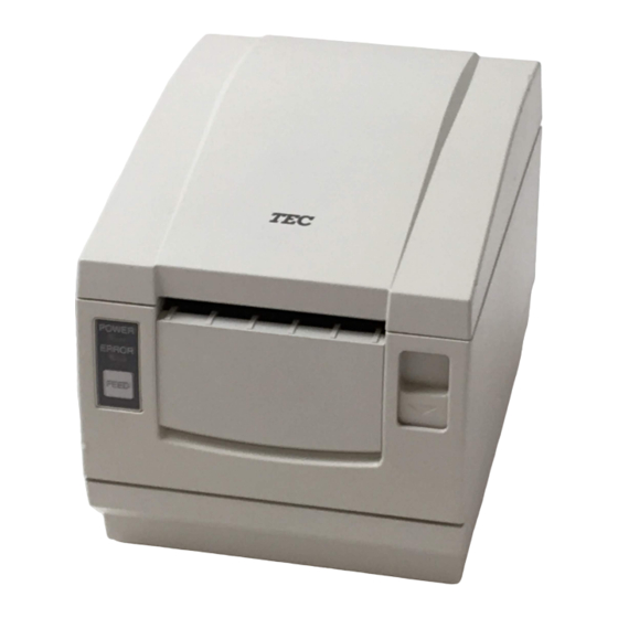
Open the Carton. Take the accessories out of the carton. Take out the TRST-56 printer and remove the pads. Place the TRST-56 printer on a level surface. Accessories TEC Thermal Printer TRST-56 SERIES Owner's Manual TOSHIBA TEC CORPORATION TRST-56 Printer Carton Fig. -
Page 5: Power Cord
1. UNPACKING EO18-13004 1.3 Power Cord 1.3 Power Cord As the power cord is not supplied with this printer, locally purchase the power cord which meets the following standard. For USA and Canada: Power Supply Cord – UL and CSA approved, type SVT, 18/3AWG, rated min. 125V, 10A Attached Plug and Appliance Coupler –... -
Page 6: Installation Procedure
2. INSTALLATION PROCEDURE EO18-13004 2.1 Connecting the TRST-56 to the POS Terminal 2. INSTALLATION PROCEDURE WARNING! 1. Turn the POS terminal OFF before connecting the TRST-56 printer. 2. Plug the TRST-56 power cord into the AC outlet on the wall for power supply. Do not obtain the AC power from the AC outlet of the POS terminal such as ST-5500, ST-5600, etc., because the rush current at the TRST-56 power on may exceed the rating of the power switch of the POS terminal. - Page 7 2. INSTALLATION PROCEDURE EO18-13004 2.1 Connecting the TRST-56 to the POS Terminal Connect the interface cable to the POS terminal, and then insert the power cord into the AC outlet. POS Terminal Interface Cable LPT1 Fig. 2-3 NOTE: The above figure shows the example of the interface cable which is connected to the LPT1 port (Parallel interface) on the ST-5600.
-
Page 8: Connecting The Drawer
Doing so may cause a failure of the phone line and the printer. 4. The drawers which are provided with TOSHIBA TEC standard drawer interface (4-pin modular type connector) cannot be connected to this printer. -
Page 9: Separating The Power Supply Unit (Ac Adapter)
2. INSTALLATION PROCEDURE EO18-13004 2.3 Separating the Power Supply Unit (AD Adapter) 2.3 Separating the Power Supply Unit (AC Adapter) Disconnect the AC adapter cable from the printer. NOTE: Before disconnect the AC adapter cable, unlock the connector. Remove the four ST-3x8 screws to detach the power case SA. Cut the cable band which ties the AC adapter cable. -
Page 10: Disassembly And Reassembly
3. DISASSEMBLY AND REASSEMBLY EO18-13004 3.1 Maintenance Tools 3. DISASSEMBLY AND REASSEMBLY WARNING! 1. Disconnect the power cord before disassembling the printer. 2. The print head becomes very hot while printing. Never touch the print head to avoid getting burned. CAUTION! 1. -
Page 11: Disassembling The Main Body
DISASSEMBLY AND REASSEMBLY EO18-13004 3.2 Disassembling the Main Body 3.2 Disassembling the Main Body 3.2.1 Removing the Power Case SA Disconnect the AC adapter cable from the printer. NOTE: Before disconnect the AC adapter cable, unlock the connector. Remove the four ST-3x8 screws to detach the power case SA. AC Adapter Cable Power Case SA Fig. -
Page 12: Removing The Top Cover Sa
DISASSEMBLY AND REASSEMBLY EO18-13004 3.2 Disassembling the Main Body 3.2.3 Removing the Top Cover SA Remove the two ST-3x6 screws which secure the top cover SA. Unhook tabs B of the frame by inserting a screw driver into the square holes. Lift the top cover SA so as not to catch the power switch on the top cover SA. -
Page 13: Removing The If Pcb Ass'y And Control Pcb Ass'y
DISASSEMBLY AND REASSEMBLY EO18-13004 3.2 Disassembling the Main Body 3.2.5 Removing the IF PCB Ass’y and Control PCB Ass’y Remove the two ST-3x6 screws which secure the IF PCB ass’y to the bottom chassis SA. Disconnect the IF PCB ass’y from the control PCB ass’y. Remove the two ST-3x6 screws which secure the control PCB ass’y to the bottom chassis SA. -
Page 14: Removing The Operation Panel Sa And
DISASSEMBLY AND REASSEMBLY EO18-13004 3.2 Disassembling the Main Body 3.2.7 Removing the Operation Panel SA and Front Cover Remove the operation panel SA from the front by pushing its back. Remove the front cover from the top cover SA. Top Cover SA Front Cover Operation Panel SA Fig. -
Page 15: Disassembling The Mechanism Unit
DISASSEMBLY AND REASSEMBLY EO18-13004 3.3 Disassembling the Mechanism Unit 3.3 Disassembling the Mechanism Unit 3.3.1 Removing the Top Chassis SA Remove the mechanism unit. (Refer to Section 3.2.4 Removing the Mechanism Unit.) Release the head cable ass’y from the cable holders. Remove the E-2 retaining ring from the left end of the chassis shaft. -
Page 16: Removing The Center Frame Sa
DISASSEMBLY AND REASSEMBLY EO18-13004 3.3 Disassembling the Mechanism Unit Removing the Platen Remove the two E-4 retaining rings from both ends of the platen shaft. Pull out the platen gear from the left side of the platen. Pull out both platen bushings and remove the two E-4 retaining rings from the platen. Platen Bushing Platen Gear Platen... -
Page 17: Removing The Gears
DISASSEMBLY AND REASSEMBLY EO18-13004 3.3 Disassembling the Mechanism Unit Removing the Center Frame Remove the PNE lever ass’y, sensor plate, guide roller and DIP switch cover with the slider. Remove the BT-2.6x6 screw to detach the sensor PCB ass’y. Remove the slider from the DIP switch cover. Slider DIP Switch Cover Guide Roller... -
Page 18: Removing The Auto Cutter Sa
DISASSEMBLY AND REASSEMBLY EO18-13004 3.3 Disassembling the Mechanism Unit 3.3.5 Removing the Auto Cutter SA Remove the four ST-3x6 screws to remove the auto cutter SA. Auto Cutter SA Main Chassis Fig. 3-16 ST-3x6 Removing the Auto Cutter and Its Peripheral Parts Remove the two M-3x4 screws and slide the auto cutter in the direction of the arrow to remove. -
Page 19: Removing The Pressure Arms
DISASSEMBLY AND REASSEMBLY EO18-13004 3.3 Disassembling the Mechanism Unit 3.3.7 Removing the Pressure Arms Unhook the EXT spring-01and remove the pressure arm-L from the main chassis. Unhook the EXT spring-01 and remove the pressure arm-R from the main chassis. Remove the ST-3x6 screw from the right side of the main chassis. ST-3x6 Pressure Arm-R EXT Spring-01... -
Page 20: Removing The Top Chassis Sa
DISASSEMBLY AND REASSEMBLY EO18-13004 3.3 Disassembling the Mechanism Unit 3.3.9 Removing the Top Chassis SA CAUTION! Care must be taken not to touch the print head element when removing and reassembling it from/to the top chassis SA. Release the head cable ass’y from the cable holder. Remove the wire cover from the top chassis SA. -
Page 21: Lubrication
DISASSEMBLY AND REASSEMBLY EO18-13004 3.4 Reassembly Procedure 3.4 Reassembly Procedure Reassemble each part in the reverse order of the disassembly procedure described in Sections 3.2 and 3.3. 3.5 Lubrication Apply specified lubricant to the specified locations. 3.5.1 Lubricant Grease: Molykote EM-10L 3.5.2 Where to Lubricate A. -
Page 22: Dip Switch Function
4. DIP SWITCH FUNCTION EO18-13004 4.1 DIP Switch 4. DIP SWITCH FUNCTION The DIP switch locates under the DIP switch cover. Open the printer cover. Then, remove the receipt roll and DIP switch cover. The function of each DIP switch is shown below. DIP Switch Cover Fig. -
Page 23: Dip Switch
4. DIP SWITCH FUNCTION EO18-13004 4.1 DIP Switch 4.1.2 DIP Switch 2 Function Default International See table below. characters JIS/Shift JIS (NOTE) Shift JIS Handshake Off-line Receive buffer full (condition for BUSY) Receive buffer full Reserved ---- ---- Reserved ---- ---- Reserved ----... -
Page 24: Self Test Print
5. SELF TEST PRINT EO18-13004 5. SELF TEST PRINT 5. SELF TEST PRINT When the power is turned on while pressing the [FEED] button, the printer will start a self test print. After completing the self test print, the printer will automatically cut the receipt and return to the stand- by mode. -
Page 25: Troubleshooting
6. TROUBLESHOOTING EO18-13004 6.1 Troubleshooting Procedure 6. TROUBLESHOOTING 6.1 Troubleshooting Procedure When a trouble occurs, confirm its phenomenon, locate a defective part in accordance with Section 6.2 Troubleshooting Guide, and troubleshoot as described below. ● Phenomenon: Find the corresponding phenomenon from this column. If there are multiple phenomena, take all the corresponding items into consideration. - Page 26 6. TROUBLESHOOTING EO18-13004 6.2 Troubleshooting Guide Printing failure Phenomenon Cause Check method Solution No printing Faulty DC output voltage Check whether the Use the specified AC from the AC adapter specified AC adapter is adapter. used. Faulty control PCB ass’y ----- Replace the control PCB ass’y.
- Page 27 6. TROUBLESHOOTING EO18-13004 6.2 Troubleshooting Guide Paper Feed Failure Phenomenon Cause Check method Solution Paper is not fed or fed Faulty connection of the Check the connection of Connect the connector irregularly. motor connector the motor connector. correctly. Faulty motor Measure the supply If the supply voltage voltage with a DC...
- Page 28 6. TROUBLESHOOTING EO18-13004 6.2 Troubleshooting Guide Faulty auto cutter Phenomenon Cause Check method Solution The cutter does not Faulty connection of the Check the connection of Connect the connector function auto cutter connector the auto cutter correctly. connector. Faulty DC output Check whether the Use the specified AC voltage from the AC...
-
Page 29: Periodic Maintenance
7. PERIODIC MAINTENANCE EO18-13004 7.1 Periodic Maintenance Procedure 7. PERIODIC MAINTENANCE To retain the quality and performance of this machine and to prevent unexpected troubles, the following maintenance should be performed periodically. CAUTION! Turn the power OFF when performing the maintenance. (Check item #1 to #6) 7.1 Periodic Maintenance Procedure Be sure to perform the following cleaning and checks every six months.
Need help?
Do you have a question about the TRST-56 SERIES and is the answer not in the manual?
Questions and answers