Table of Contents
Advertisement
Available languages
Available languages
Owner's Manual/Manual Del Propietario
Garage Door Opener/Abridor de puerta de cochera
For Residential Use Only/Sólo para uso residencial
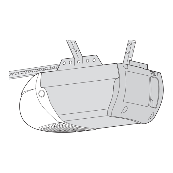
MODEL/MODELO 139.54930
Read and follow all safety rules and operating
instructions before first use of this product.
Fasten the manual near the garage door after
installation.
Periodic checks of the opener are required to
ensure safe operation.
DO NOT install on a one-piece door if using
devices or features providing unattended
close. Unattended devices and features are to
be used ONLY with sectional doors. See
page 3
Sears Brands Management Corporation, Hoffman Estates, IL 60179 U.S.A.
Leer y seguir todas las reglas de seguridad y
las instrucciones de operación antes de usar
este producto por primera vez.
Guardar este manual cerca de la puerta de la
cochera.
Se deben realizar revisiones periódicas del
abridor de puertas para asegurar su operación
segura.
NO usarlo para puertas de una sola pieza si
utiliza dispositivos de cierre automático. Los
dispositivos y funciones automáticas deben
usarse ÚNICAMENTE con puertas seccionales.
Vea la página 3.
Advertisement
Chapters
Table of Contents

Related Manuals for Craftsman 139.54930


Summary of Contents for Craftsman 139.54930
- Page 1 Owner’s Manual/Manual Del Propietario Garage Door Opener/Abridor de puerta de cochera For Residential Use Only/Sólo para uso residencial MODEL/MODELO 139.54930 Read and follow all safety rules and operating Leer y seguir todas las reglas de seguridad y instructions before first use of this product.
-
Page 2: Table Of Contents
TABLE OF CONTENTS Introduction Adjustment 28-30 Safety symbol and signal word review ....2 Introduction ........28 Unattended Operation . -
Page 3: Unattended Operation
Unattended Operation The Timer-to-Close (TTC) feature, the Craftsman Garage Door app, and Smart Garage Door and Gate Monitor are examples of unattended close and are to be used ONLY with sectional doors. Any device or feature that allows the door to close without being in the line of sight of the door is considered unattended close. -
Page 4: Planning
Planning Identify the type and height of your garage door. Survey your Do you have an access door in addition to the garage door? If garage area to see if any of the conditions below apply to your not, Model 139.53702 Emergency Key Release is required. See installation. - Page 5 Planning (Continued) ONE-PIECE DOOR INSTALLATIONS Generally, a one-piece door does not require reinforcement. If Without a properly working safety reversal system, persons (particularly small children) could be SERIOUSLY INJURED or your door is lightweight, refer to the information relating to KILLED by a closing garage door.
-
Page 6: Carton Inventory
Carton Inventory Your garage door opener is packaged in one carton which Hardware for assembly and installation is shown on the next contains the motor unit and all parts illustrated below. page. Save the carton and packing material until installation and Accessories will depend on the model purchased. -
Page 7: Hardware Inventory
Hardware Inventory Separate all hardware and group as shown below for the assembly and installation procedures. ASSEMBLY HARDWARE Idler Bolt Lock Nut 1/4"-20 Washer 1/4" Nut 3/8"-16 133A0087 Master Link (2) 001A0995 Bolt 1/4"-20x2-1/2 171A0547 Lock Washer 3/8" Spacer (2) 019A0047 Trolley Threaded Shaft 109B0018... -
Page 8: Assemble The Rail And Install The Trolley
ASSEMBLY STEP 1 Assemble the Rail and Install the Trolley To prevent INJURY from pinching, keep hands and fingers away To avoid installation difficulties, do not run the garage from the joints while assembling the rail. door opener until instructed to do so. The front rail has a cut out “window”... -
Page 9: Install The Idler Pulley
ASSEMBLY STEP 3 Install the Idler Pulley 1. Lay the chain/cable beside the rail, as shown. Grasp the end of the cable and pass approximately 12" (30 cm) of cable through the window. Allow it to hang until Assembly Step 4. 2. -
Page 10: Install The Chain/Cable
ASSEMBLY STEP 4 Install the Chain/Cable 1. Pull the cable around the idler pulley and toward the trolley. To avoid possible SERIOUS INJURY to finger from moving garage door opener: 2. Connect the cable to the retaining slot on the trolley, as shown (Figure 1). -
Page 11: Tighten The Chain
ASSEMBLY STEP 5 Tighten the Chain Figure 1 Trolley Outer Lock Threaded 1. Spin the inner nut and lock washer down the trolley threaded Washer Shaft To Tighten Outer Nut shaft, away from the trolley. 2. To tighten the chain, turn outer nut in the direction shown (Figure 1). -
Page 12: Determine The Header Bracket Location
INSTALLATION STEP 1 Unfinished OPTIONAL Determine the Header Bracket Location Ceiling CEILING MOUNT HEADER BRACKET To prevent possible SERIOUS INJURY or DEATH: Header Wall Header bracket MUST be RIGIDLY fastened to structural Vertical Centerline support on header wall or ceiling, otherwise garage door of Garage Door might NOT reverse when required. -
Page 13: Install The Header Bracket
INSTALLATION STEP 2 HARDWARE SHOWN ACTUAL SIZE Install the Header Bracket You can attach the header bracket either to the wall above the garage door, or to the ceiling. Follow the instructions which will Lag Screw work best for your particular requirements. Do not install the 5/16"-9x1-5/8"... -
Page 14: Attach The Rail To The Header Bracket
INSTALLATION STEP 3 Attach the Rail to the Header Bracket 1. Position the opener on the garage floor below the header bracket. Use packing material as a protective base. NOTE: If the door spring is in the way, you will need help. Have someone hold the opener securely on a temporary support to allow the rail to clear the spring. -
Page 15: Position The Opener
INSTALLATION STEP 4 Position the Opener To prevent damage to garage door, rest garage door opener rail Follow instructions which apply to your door type as illustrated. on 2x4 placed on top section of door. SECTIONAL DOOR OR ONE-PIECE DOOR WITH TRACK A 2x4 laid flat is convenient for setting an ideal door-to-rail distance. -
Page 16: Hang The Opener
INSTALLATION STEP 5 Hang the Opener To avoid possible SERIOUS INJURY from a falling garage door Three representative installations are shown. Yours may be opener, fasten it SECURELY to structural supports of the garage. different. Hanging brackets should be angled (Figure 1) to provide Concrete anchors MUST be used if installing ANY brackets into rigid support. -
Page 17: Install The Light
INSTALLATION STEP 6 Install the Light To prevent possible OVERHEATING of the end panel or light 1. Press the release tabs on both sides of lens. Gently rotate lens socket: back and downward until the lens hinge is in the fully open Use ONLY A19 incandescent (100W maximum) or compact position. -
Page 18: Fasten The Door Bracket
INSTALLATION STEP 8 Fasten the Door Bracket Follow instructions which apply to your door type as illustrated Fiberglass, aluminum or lightweight steel garage doors WILL below or on the following page. REQUIRE reinforcement BEFORE installation of door bracket. Contact your door manufacturer for reinforcement kit. A horizontal reinforcement brace should be long enough to be secured to two or three vertical supports. - Page 19 Fasten the Door Bracket (Continued) HARDWARE SHOWN ACTUAL SIZE ONE-PIECE DOORS Please read and comply with the warnings and reinforcement instructions on the previous page. They apply to one-piece doors also. Self-Threading Screw 1/4"-14x5/8" Center the door bracket on the top of the door, in line with the header bracket as shown.
- Page 20 INSTALLATION STEP 9 Pulley Figure 1 Connect Door Arm to Trolley 8" (20 cm) min. Follow instructions which apply to your door type as illustrated below and on the following page. Inner Outer IMPORTANT: The groove on the straight door arm MUST face Trolley Trolley away from the curved door arm (Figure 4).
-
Page 21: Attach The Warning Labels
Figure 5 Connect Door Arm to Trolley (Continued) CORRECT INCORRECT ALL ONE-PIECE DOORS Straight IMPORTANT: The groove on the straight door arm MUST face Door Arm Straight away from the curved door arm (Figure 5). Door Arm Curved Curved 1. Close the door. Disconnect the trolley by pulling the (Groove Door Arm Door... -
Page 22: Install The Door Control
INSTALLATION STEP 11 Install the Door Control Locate door control within sight of door, at a minimum height of 5 To prevent possible SERIOUS INJURY or DEATH from feet (1.5 m) where small children cannot reach, away from moving electrocution: Be sure power is NOT connected BEFORE installing door parts of door and door hardware. -
Page 23: Install The Protector System
INSTALLATION STEP 12 Install The Protector System ® IMPORTANT INFORMATION ABOUT THE SAFETY REVERSING Be sure power is NOT connected to the garage door opener SENSORS BEFORE installing the safety reversing sensor. The safety reversing sensors must be connected and aligned To prevent SERIOUS INJURY or DEATH from closing garage correctly before the garage door opener will move in the door:... - Page 24 ® Install The Protector System (Continued) Figure 1 DOOR TRACK MOUNT (RIGHT SIDE) INSTALLING THE BRACKETS Be sure power to the opener is disconnected. Install and align Door the brackets so the sensors will face each other across the garage Track door, with the beam no higher than 6"...
-
Page 25: Install The Protector System
® Install The Protector System (Continued) Figure 5 MOUNTING AND WIRING THE SAFETY REVERSING SENSORS Wing Carriage Mounting: Bolt 1. Slide a 1/4"-20x1/2" carriage bolt head into the slot on each sensor. Use wing nuts to fasten sensors to brackets, with lenses pointing toward each other across the door. -
Page 26: Electrical Requirements
INSTALLATION STEP 13 Electrical Requirements To avoid installation difficulties, do not run the opener at To prevent possible SERIOUS INJURY or DEATH from this time. electrocution or fire: To reduce the risk of electric shock, your garage door opener has Be sure power is NOT connected to the opener, and a grounding type plug with a third grounding pin. -
Page 27: Aligning The Safety Reversing Sensors
INSTALLATION STEP 14 Aligning the Safety Reversing Sensors The door will not close if the sensors have not been installed Figure 1 and aligned correctly. When the light beam is obstructed or misaligned while the door is closing, the door will reverse and the garage door opener lights will flash ten times. -
Page 28: Adjustment
ADJUSTMENT Introduction Your garage door opener is designed with electronic controls to Without a properly installed safety reversal system, persons make setup and adjustments easy. The adjustments allow you to (particularly small children) could be SERIOUSLY INJURED or program where the door will stop in the open (UP) and close KILLED by a closing garage door. -
Page 29: Program The Travel
ADJUSTMENT STEP 1 Program the Travel Without a properly installed safety reversal system, persons 1. Press and hold the (particularly small children) could be SERIOUSLY INJURED or Adjustment Button until the KILLED by a closing garage door. UP Button begins to flash and/or a beep is heard. -
Page 30: Test The Safety Reversal System
ADJUSTMENT STEP 2 Test the Safety Reversal System TEST Without a properly installed safety reversal system, persons (particularly small children) could be SERIOUSLY INJURED or 1. With the door fully open, place a 1-1/2 inch (3.8 cm) board (or KILLED by a closing garage door. a 2x4 laid flat) on the floor, centered under the garage door. -
Page 31: Operation
OPERATION IMPORTANT SAFETY INSTRUCTIONS To reduce the risk of SEVERE INJURY or DEATH: 1. READ AND FOLLOW ALL WARNINGS AND INSTRUCTIONS. 9. After ANY adjustments are made, the safety reversal system 2. ALWAYS keep remote controls out of reach of children. MUST be tested. -
Page 32: Features
100 billion new codes. Older activated the door will close. If the garage door opener senses an Craftsman accessories are not compatible. obstruction while closing, the door will reverse. If the obstruction Accessories... -
Page 33: Remote Control
To program additional accessories refer to the any accessory you wish to use. instructions provided with the accessory or visit ERASE ALL REMOTE CONTROLS, KEYLESS ENTRIES AND www.craftsman.com. If your vehicle is equipped with a SMART CONTROL DEVICES FROM GARAGE DOOR OPENER ® Homelink , you may require an external adapter depending on the 1. -
Page 34: To Open The Door Manually
To Open the Door Manually Trolley DISCONNECT THE TROLLEY To prevent possible SERIOUS INJURY or DEATH from a falling 1. The door should be fully closed if garage door: possible. Trolley If possible, use emergency release handle to disengage 2. Pull down on the emergency release Release Arm trolley ONLY when garage door is CLOSED. -
Page 35: Troubleshooting
TROUBLESHOOTING DIAGNOSTIC CHART Your garage door opener is programmed with self-diagnostic capabilities. The UP and DOWN arrows on the garage door opener flash the diagnostic codes. UP ARROW DOWN ARROW SYMPTOM SOLUTION FLASH(ES) FLASH(ES) The garage door opener will not Safety sensors are not installed, connected, or wires may be close and the light bulbs flash. -
Page 36: Repair Protection Agreements
REPAIR PROTECTION AGREEMENTS ® Congratulations on making a smart purchase. Your new Craftsman product is designed and manufactured for years of dependable operation. But like all products, it may require repair from time to time. That’s when having a Repair Protection Agreement can save you money and aggravation. -
Page 37: Repair Parts
REPAIR PARTS Rail Assembly Parts PART DESCRIPTION 4A1008 Master link kit 41C5141-1 Complete trolley assembly 041A5665 Complete rail 144C56 Pulley kit 41A5807 Chain and cable 12D598-1 “U” bracket NOT SHOWN 183A163 Wear pads Installation Parts PART DESCRIPTION 041A8359 Door Control 10A20 3V CR2032 Lithium battery 041A7633... -
Page 38: Motor Unit Assembly Parts
Motor Unit Assembly Parts PART PART DESCRIPTION DESCRIPTION 041A5615 Chain Spreader 12A373 Capacitor Bracket 041C4220A Gear and sprocket 041A7442 Universal motor 041A2817 Drive and worm gear 041D7742-7 Travel Module (passpoint) 041A5484-5 Front End Panel with all labels 041D8400 Motor Cover Kit 175C0279 Light Socket 045ACT... -
Page 39: Accessories
WARRANTY RESTRICTION This Craftsman Garage Door Opener Limited Warranty does not cover light bulbs, which are expendable parts, or repair parts necessary because of operator abuse or negligence, including the failure to install, adjust and operate this garage door opener according to instructions contained in the owner’s manual. This limited warranty also does not cover any problems caused by interference. - Page 40 CONTENIDO Introducción Ajustes 28-30 Revisión de los símbolos y términos de seguridad ....2 Introducción ................28 Operaciones automatizadas ............3 Programación del desplazamiento ........... 29 Preparación de la puerta de su cochera ........3 Pruebe el sistema de reversa de seguridad ......30 Herramientas necesarias ............
-
Page 41: Operaciones Automatizadas
Operaciones automatizadas La función temporizador de cierre (TTC), la aplicación para el abre-puertas de garaje de Craftsman, y el abre-puertas de garaje inteligente y el monitor del portón son ejemplos de cierre en estado pasivo y se deben usar SOLO con puertas seccionales. Todo dispositivo o función que cierre la puerta sin que el usuario la tenga directamente a la vista se considera cierre automatizado. -
Page 42: Planificación
Planificación ¿Hay otra puerta que dé acceso a la cochera? Si no es así, será Identifique la altura y el tipo de puerta de garaje que tiene. Revise el área de necesario contar con el sistema de llave de emergencia Modelo su cochera y observe si alguna de las siguientes instalaciones corresponden 139.53702. - Page 43 Planificación (continuación) INSTALACIÓN CON PUERTAS DE UNA SOLA PIEZA Generalmente una puerta de una sola pieza no requiere de refuerzos Sin un sistema de reversa de seguridad que funcione debidamente, al adicionales. Si usted tiene una puerta de material liviano y quiere cerrar la puerta del garaje se corre el riesgo de que las personas (y en particular los niños pequeños) sufran LESIONES GRAVES O INCLUSO LA reforzarla, consulte la información respecto a puertas seccionales,...
-
Page 44: Inventario De La Caja De Cartón
Inventario de las cajas de cartón Su abridor viene empacado en una caja de cartón que contiene el motor y Toda la tornillería y las piezas necesarias para el montaje e instalación de las piezas que se muestran en la siguiente ilustración. Tome nota de que su puerta se ilustran en la siguiente página. -
Page 45: Inventario De Piezas
Inventario de piezas Antes de la instalación, organice todas las piezas en grupos como se muestra en la siguiente ilustración. TORNILLERÍA Y PIEZAS PARA EL MONTAJE Perno loco Tuerca de seguridad de Arandela de Tuerca de 1/4 de pulg.-20 1/4 de pulg. 3/8 pulg.-16 Enlace maestro (2) 133A0087... -
Page 46: Montaje
MONTAJE, PASO 1 Monte el Riel e instale el Trole No encienda ni use el abridor de la puerta de cochera hasta que Para prevenir LESIONES por presión, mantenga las manos y los dedos llegue al paso de la instalación correspondiente, de otra manera alejados de las uniones mientras se ensambla el riel. -
Page 47: Instale La Polea Loca
MONTAJE, PASO 3 Instale la polea loca 1. Ponga la cadena y cable a un lado del riel como se muestra en la ilustración. Sujete el extremo del cable y pase aproximadamente 30 cm (12 pulg.) de cable por la ventana. Déjelo que cuelgue hasta que lleque al Paso 4 de Montaje. - Page 48 MONTAJE, PASO 4 Instalación del cadena/cable 1. Coloque el cable alrededor de la polea y tírela hacia el trole. Para evitar posibles LESIONES GRAVES en los dedos causadas por las 2. Enganche el cable en la ranura de retención del trole como se muestra partes móviles del abre-puertas de garaje: en la ilustración (Figura 1).
-
Page 49: Apriete La Cadena
MONTAJE, PASO 5 Apretar la cadena Figura 1 Tuerca Arandela Eje roscado 1. Girar la tuerca interna y la arandela de presión en el eje roscado del externa de seguro del trole trole, en sentido opuesto al trole. Para apretar la tuerca externa 2. -
Page 50: La Ménsula Del Cabezal
INSTALACIÓN PASO 1 Cielo raso Determinar la localización de soporte de cabecera sin acabado INSTALACIÓN OPCIONAL DE LA MÉNSULA DEL CABEZAL EN EL CIELO RASO Para evitar posibles LESIONES GRAVES o la MUERTE: Pared delantera (2x4 pulg.) La ménsula del cabezal DEBE quedar RÍGIDAMENTE sujeta al soporte estructural en la pared delantera o en el cielo raso, de no ser así... - Page 51 INSTALACIÓN PASO 2 ESTAS PIEZAS SE MUESTRAN EN SU TAMAÑO REAL Instalación del soporte de travesaño La ménsula del cabezal se puede sujetar a la pared sobre la puerta del garaje o en el cielo raso. Siga las instrucciones que sean las más adecuadas para las necesidades de su garaje.
-
Page 52: Coloque El Riel En La Ménsula Del Cabezal
INSTALACIÓN PASO 3 Coloque el riel en la ménsula del cabezal 1. Coloque el abridor sobre el piso de la garaje debajo de la ménsula del cabezal. Use el hule espuma del empaque como base para protegerlo. NOTA: Si el resorte de la puerta está obstruido, va a necesitar ayuda. Otra persona tendrá... -
Page 53: Coloque El Abridor En Posición
INSTALACIÓN PASO 4 Coloque el abridor Siga las instrucciones correspondientes al tipo de puerta de su cochera, Para evitar que la puerta del cochera sufra daños, apoye el riel del abre- como se muestra en la ilustración. puertas de garaje sobre un pedazo de madera de 5 x 10 cm (2 x 4 pulg.) colocado en la sección superior de la puerta. -
Page 54: Cuelgue El Abridor
INSTALACIÓN PASO 5 Cuelgue el abridor Se muestran tres instalaciónes representativas. Quizá su instalación sea Para evitar la posibilidad de una LESIÓN GRAVE si se cae el abre-puertas diferente. Las soportes colgantes se deben colocar en ángulo (Figura 1) de garaje, sujételo FIRMEMENTE a los soportes estructurales del garaje. para lograr un soporte rígido. -
Page 55: Instale La Luz
INSTALACIÓN PASO 6 Instale la luz 1. Oprima las lengüetas de desenganche ubicados a ambos Para evitar un posible SOBRECALENTAMIENTO del portabombillas: lados de la lente. Rote la lente suavemente hacia atrás y hacia Use ÚNICAMENTE bombillas incandescentes A19 (100 voltios máximo) o fluorescentes compactas (26 voltios máximo). -
Page 56: Sujete La Ménsula De La Puerta
INSTALACIÓN PASO 8 Sujete la ménsula de la puerta Siga las instrucciones que correspondan al tipo de puerta de cochera que Para puertas de garaje de fibra de vidrio, acero fino o aluminio, es usted tenga, como se muestra en la ilustración o en la página siguiente. NECESARIO un refuerzo ANTES de instalar la ménsula de puerta. - Page 57 Sujete la ménsula de la puerta (continúa) PUERTAS DE UNA SOLA PIEZA Lea y respete todas las advertencias e instrucciones respecto a los ESTAS PIEZAS SE refuerzos, contenidas en la página anterior. Todos los refuerzos para su MUESTRAN EN SU puerta de una sola pieza son los mismos.
-
Page 58: Conectar El Brazo De La Puerta Al Trole
INSTALACIÓN PASO 9 Polea Lo menos Figura 1 Conectar el brazo de la puerta al trole 20 cm (8 pulg.) Siga las instrucciones que correspondan al tipo de puerta de cochera que usted tenga, como se muestra a continuación y en las dos páginas siguientes. - Page 59 Figura 5 Conecte el brazo de la puerta al trole (continúa) CORRECTO INCORRECTO TODAS LAS PUERTAS DE UNA SOLA PIEZA IMPORTANTE: El ranura en el brazo recto de la puerta DEBE voltéese del Brazo brazo curvado de la puerta (Figura 5). recto Brazo recto...
-
Page 60: Instalar El Control De La Puerta
INSTALACIÓN PASO 11 Instalar el control de la puerta Ubique el control de la puerta de manera que quede a la vista desde la Para evitar la posibilidad de una LESIÓN GRAVE o INCLUSO LA MUERTE puerta y a una altura mínima de 1.5 m (5 pies) donde los niños pequeños por electrocución: no lo puedan alcanzar y lejos de las partes móviles de la puerta y de la ANTES de instalar el control de la puerta, cerciórese de que la energía... -
Page 61: Instalación De Protector System
INSTALACIÓN PASO 12 Instalación de Protector System ® INFORMACIÓN IMPORTANTE SOBRE EL SENSOR DE REVERSA DE La alimentación eléctrica al abre-puertas debe estar cortada ANTES de SEGURIDAD instalar los sensores de seguridad de reversa. El sensor de reversa de seguridad debe estar bien conectado y alineado Para evitar la posibilidad de sufrir una LESIÓN GRAVE o INCLUSO LA antes de que el abre-puertas de garaje se mueva hacia abajo. - Page 62 ® Instale la Protector System (continua) Figura 1 INSTALACIÓN EN EL CARRIL DE LA PUERTA (LADO DERECHO) INSTALACION DE LA MÉNSULA Asegúrese de que el abridor no esté conectado a la corriente eléctrica. Carril de Instale y alinee las mensulas de manera que los sensores esten uno frente al la puerta otro en los lados opuestos de la puerta, a una distancia máxima de 15 cm Reborde...
- Page 63 ® Instale la Protector System (continua) Figura 5 MONTAJE Y CABLEADO DE LOS SENSORES DEL SISTEMA DE Tuerca de mariposa SEGURIDAD DE REVERSA Perno de Montaje: coche 1. Deslice la cabeza de un perno de coche de 1/4 de pulg.-20x1/2 de pulg. dentro de la ranura de los sensores.
-
Page 64: Requisitos Para La Instalación Eléctrica
INSTALACIÓN PASO 13 Requisitos para la instalación eléctrica Para evitar problemas con la instalación, no opere el abre-puertas de Para evitar la posibilidad de una LESIÓN GRAVE O INCLUSO LA MUERTE garaje ahora. por electrocución o incendio: Para reducir el riesgo de descarga eléctrica, su abre-puertas de garaje viene Asegúrese de que el abre-puertas NO esté... -
Page 65: Alineación De Los Sensores De Reversa De Seguridad
INSTALACIÓN PASO 14 Alineación de los sensores de reversa de seguridad La puerta no se cerrará si los sensores no están instalados y alineados Figura 1 correctamente. Si el haz de luz está desalineado o se ve obstaculizado cuando la puerta se está... -
Page 66: Introducción
AJUSTES Introducción Si el sistema de retroceso de seguridad no se ha instalado debidamente, las personas (y los niños pequeños en particular) podrían sufrir El abre-puerta tiene controles electrónicos que facilitan su instalación y LESIONES GRAVES o INCLUSO LA MUERTE cuando se cierra la puerta regulación. -
Page 67: Programación Del Desplazamiento
AJUSTES, PASO 1 Programación del desplazamiento 1. Presione y mantenga Si el sistema de auto-reversa de seguridad no se ha instalado presionado el botón de Ajuste debidamente, las personas (y los niños pequeños en particular) podrían sufrir LESIONES GRAVES o INCLUSO LA MUERTE cuando se cierre la hasta que el botón ARRIBA puerta del garaje. -
Page 68: Pruebe El Sistema De Reversa De Seguridad
AJUSTES, PASO 2 Pruebe el sistema de reversa de seguridad PRUEBA Si el sistema de reversa de seguridad no se ha instalado debidamente, las personas (y los niños pequeños en particular) podrían sufrir LESIONES 1. Con la puerta completamente abierta, coloque una tabla de 3.8 cm GRAVES o INCLUSO LA MUERTE cuando se cierre la puerta del garaje. -
Page 69: Operación
OPERACIÓN INSTRUCCIONES IMPORTANTES DE SEGURIDAD Para reducir el riesgo de LESIONES GRAVES o la MUERTE: 9. Después de llevar a cabo cualquier ajuste, SE DEBE probar el sistema 1. LEA Y SIGA TODAS LAS INSTRUCCIONES Y ADVERTENCIAS. de reversa de seguridad. 2. -
Page 70: Funciones
Si una obstrucción interrumpe el haz Antíguos accesorios Craftsman no son compatíbles. del sensor, las luces del abre-puertas de garaje parpadearán 10 veces. Sin... -
Page 71: Control Remoto
1. Mantenga presionado el botón programar (aprender) en el abridor de la Los controles remotos Craftsman mas antiguos NO son compatibles. La puerta de cochera hasta que se apague el LED (aproximadamente 6 programación puede realizarse a través del control de la puerta o el botón segundos). -
Page 72: Para Abrir La Puerta Manualmente
Trole Para abrir la puerta manualmente CÓMO DESCONECTAR EL TROLE 1. Si es posible, la puerta se debe cerrar Para evitar la posibilidad de una LESIÓN GRAVE O INCLUSO LA MUERTE si la puerta del garaje se cae: completamente. Brazo de liberación De ser posible, use el desenganche de emergencia para soltar el carro 2. -
Page 73: Resolución De Problemas
RESOLUCIÓN DE PROBLEMAS TABLA DE DIAGNÓSTICO El abre-puertas de garaje viene programado con funciones de autodiagnóstico. Las flechas hacia ARRIBA y ABAJO se encienden para mostrar los códigos de diagnóstico. LA FLECHA HACIA LA FLECHA HACIA SÍNTOMA SOLUCIÓN ARRIBA ABAJO PARPADEA PARPADEA El abre-puertas de garaje no cierra la Sensores de seguridad no instalados, no conectados o cable cortado. -
Page 74: Acuerdos De Protección Para Reparaciones
ACUERDOS DE PROTECCIÓN PARA REPARACIONES ® Felicitaciones por hacer una compra inteligente. Su nuevo producto Craftsman está diseñado y fabricado para años de operación confiable. Pero como todos los productos, puede requerir reparaciones de vez en cuando. Ahí es cuando un Acuerdo de Protección para Reparaciones le puede ahorrar dinero y molestias. -
Page 75: Accesorios
RESTRICCIÓN APLICABLE A LA GARANTÍA Esta Garantía Limitada para Dispositivo de Apertura de Puerta de Garaje de Craftsman no cubre bombillas, que son componentes fungibles, o piezas de repuesto necesarias debido a uso indebido o negligencia del operario, incluyendo falta de instalación, ajuste y operación de este dispositivo de apertura de puerta de garaje conforme a las instrucciones contenidas en el manual de instalación.
Need help?
Do you have a question about the 139.54930 and is the answer not in the manual?
Questions and answers