Table of Contents
Advertisement
Quick Links
Owner's Manual & Safety Instructions
Save This Manual
operating, inspection, maintenance and cleaning procedures. Write the product's serial number in the
back of the manual near the assembly diagram (or month and year of purchase if product has no number).
Keep this manual and the receipt in a safe and dry place for future reference.
When unpacking, make sure that the product is intact
and undamaged. If any parts are missing or broken,
please call 1-888-866-5797 as soon as possible.
©
Copyright
2015 by Harbor Freight Tools
No portion of this manual or any artwork contained herein may be reproduced in
any shape or form without the express written consent of Harbor Freight Tools.
Diagrams within this manual may not be drawn proportionally. Due to continuing
improvements, actual product may differ slightly from the product described herein.
Tools required for assembly and service may not be included.
Keep this manual for the safety warnings and precautions, assembly,
Visit our website at: http://www.harborfreight.com
Email our technical support at: productsupport@harborfreight.com
®
. All rights reserved.
Read this material before using this product.
Failure to do so can result in serious injury.
SAVE THIS MANUAL.
REV 15k
Advertisement
Table of Contents

Related Manuals for Chicago Electric 35 LB


Summary of Contents for Chicago Electric 35 LB
- Page 1 Owner’s Manual & Safety Instructions Save This Manual Keep this manual for the safety warnings and precautions, assembly, operating, inspection, maintenance and cleaning procedures. Write the product’s serial number in the back of the manual near the assembly diagram (or month and year of purchase if product has no number). Keep this manual and the receipt in a safe and dry place for future reference.
-
Page 2: Table Of Contents
Table of contents Safety ............2 Maintenance ..........12 Specifications ..........8 Parts List and Diagram ......14 Setup ............8 Warranty ............ 16 Operation ........... 10 WARNING SyMBOLS AND DEFINITIONS This is the safety alert symbol. It is used to alert you to potential personal injury hazards. -
Page 3: Work Area Safety
Work area safety 1. Keep work area clean and well lit. 3. Keep children and bystanders Cluttered or dark areas invite accidents. away while operating a power tool. Distractions can cause you to lose control. 2. Do not operate power tools in explosive atmospheres, such as in the presence of flammable liquids, gases or dust. -
Page 4: Power Tool Use And Care
power tool use and care 1. Do not force the power tool. Use the 5. Maintain power tools. check for misalignment correct power tool for your application. or binding of moving parts, breakage of parts and any other condition that may affect the The correct power tool will do the job better and power tool’s operation. -
Page 5: Vibration Safety
16. WARNING: Some dust created by power sanding, 17. WARNING: The cord of this product contains sawing, grinding, drilling, and other construction lead and/or di (2-ethylhexyl) phthalate (DEHP), activities, contains chemicals known to the State chemicals known to the State of California of California to cause cancer and birth defects or to cause cancer, and birth defects or other other reproductive harm. - Page 6 Grounding TO pREVENT ELEcTRIc SHOcK AND DEATH FROM INcORREcT GROUNDING WIRE cONNEcTION: check with a qualified electrician if you are in doubt as to whether the outlet is properly grounded. Do not modify the power cord plug provided with the tool. Never remove the grounding prong from the plug.
-
Page 7: Extension Cords
Extension cords 1. Grounded tools require a three wire extension cord. 7. Make sure the extension cord is properly wired Double Insulated tools can use either and in good electrical condition. Always replace a two or three wire extension cord. a damaged extension cord or have it repaired by a qualified electrician before using it. -
Page 8: Specifications
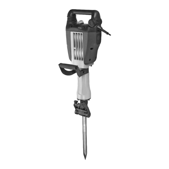
Specifications Electrical Input 120VAC / 60Hz / 15A No Load 1300 BPM Blows Per Minute 1-1/8" x 16-1/4" 1 Bull Point (28mm x 410mm) 1 Flat Point Hex Shank Chisels cU 72151735 Setup - Before Use: Read the ENTIRE IMpORTANT SAFETy INFORMATION section at the beginning of this manual including all text under subheadings therein before set up or use of this product. - Page 9 Functions Main power Handle Light power Switch carbon Brush Light Side Handle Side Knob Handle chisel Lock chisel Figure A Item 62811 For technical questions, please call 1-888-866-5797. Page 9...
-
Page 10: Operation
Operating Instructions Read the ENTIRE IMpORTANT SAFETy INFORMATION section at the beginning of this manual including all text under subheadings therein before set up or use of this product. Tool Set Up TO pREVENT SERIOUS INJURy FROM AccIDENTAL OpERATION: Make sure that the power Switch is in the OFF (O) position and the tool is unplugged from its electrical outlet before performing any procedure in this section. -
Page 11: General Operating Instructions
Installing collared chisel (Sold Separately) Note: Keep shank clean. Do not lay in dirt or dust. 4. Move Chisel Lock to locked position. 1. IMpORTANT! Clean shank with cloth, then lubricate using included Chisel Grease. 2. Move Chisel Lock to unlocked position. 3. -
Page 12: Maintenance
Maintenance and Servicing procedures not specifically explained in this manual must be performed only by a qualified technician. TO pREVENT SERIOUS INJURy FROM AccIDENTAL OpERATION: Make sure that the power Switch is in the off-position and unplug the tool from its electrical outlet before performing any procedure in this section. -
Page 13: Troubleshooting
Troubleshooting problem possible causes Likely Solutions Tool will 1. Cord not connected. 1. Check that cord is plugged in. not start. 2. No power at outlet. 2. Check power at outlet. If outlet is unpowered, turn off tool and check circuit breaker. If breaker is tripped, make sure circuit has right capacity for tool and circuit has no other loads. -
Page 14: Parts List And Diagram
parts List and Diagram part Description part Description Chisel Chuck 6201 RZ Ball Bearing Locking Lever Counter Gear Spring Column Pin 6001 RZ Bearing Cover Pull Rod M5 x 10 Embedding Screws Front Cover 6203 DD Bearing Cover Pull Rod Spring 6203 DD Ball Bearing Pull Ring 6001 RZ Ball Bearing... - Page 15 Assembly Diagram Item 62811 For technical questions, please call 1-888-866-5797. Page 15...
-
Page 16: Warranty
pLEASE READ THE FOLLOWING cAREFULLy THE MANUFACTURER AND/OR DISTRIBUTOR HAS PROVIDED THE PARTS LIST AND ASSEMBLY DIAGRAM IN THIS MANUAL AS A REFERENCE TOOL ONLY. NEITHER THE MANUFACTURER OR DISTRIBUTOR MAKES ANY REPRESENTATION OR WARRANTY OF ANY KIND TO THE BUYER THAT HE OR SHE IS QUALIFIED TO MAKE ANY REPAIRS TO THE PRODUCT, OR THAT HE OR SHE IS QUALIFIED TO REPLACE ANY PARTS OF THE PRODUCT.
Need help?
Do you have a question about the 35 LB and is the answer not in the manual?
Questions and answers