Table of Contents
Advertisement
Quick Links
Advertisement
Table of Contents

Related Manuals for Icom YPL 880


Summary of Contents for Icom YPL 880
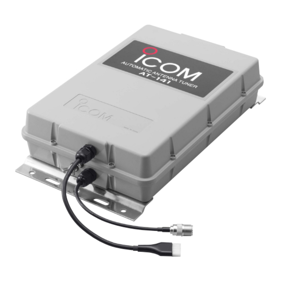
- Page 1 INSTRUCTION MANUAL HF AUTOMATIC ANTENNA TUNER AT-141...
-
Page 2: Foreword
!0 4-pin connector �������������� 1 !1 Connector pins �������������� 4 !2 Ground cable (OPC-412) ���������� 1 Icom, Icom Inc. and the logo are registered trademarks of Icom Incorporated (Japan) in the United States, the United Kingdom, Germany, France, Spain, Russia and/or other countries. -
Page 3: Table Of Contents
IMPORTANT ����������������� i Purchase these parts locally. EXPLICIT DEFINITIONS ����������� i q AWG 14×4-conductor shielded cable PRECAUTIONS ��������������� i * Icom offers an optional OPC-1465 control cable Length: 10 m; 32.8 feet SUPPLIED ACCESSORIES ���������� i w 50 Ω coaxial cable MISCELLANEOUS ITEMS�����������... -
Page 4: Antenna System
ANTENNA SYSTEM n Antenna for ship Required antenna element length Required antenna element length to achieve full Insulator performance varies according to the lowest frequency: The lowest frequency Required antenna element length Backstay operates as 1.6 MHz band 7 m; 23.0 feet or longer a long-wire antenna. -
Page 5: Coaxial Cable
ANTENNA SYSTEM n Coaxial cable Insulate the lead-in cable of the AT-141 antenna To prevent erroneous indications, keep cables as far terminal and antenna element from other metal objects. away as possible from the flux gate compass. To prevent interference, keep cables as far as Use suitable noise filters for alternators, fluorescent possible from an antenna, electric pump and other lights, etc. -
Page 6: Installations
Connect the shield line to the [GND] terminal [13.6] : Red [GND] [GND] on the transceiver. Icom offers 10 m (32.8 ft) long OPC-1465 : Black optional control cables as at right. D When connecting to Icom IC-M801E Use the optional OPC-1465, or assemble the desired length 4- conductor shielded cable and the connector kits supplied with the transceiver and the tuner. -
Page 7: Pl-259 Connector
INSTALLATIONS n PL-259 connector q Slide the coupling ring over the coaxial cable. e Slide the connector body over the cable and Strip the cable jacket and pull back to reveal 10 solder as shown below. mm of braid. Solder Solder •... -
Page 8: Cable Connections
Fix both of the coaxial and control cables to Mounting plate protect the inside connections. DO NOT pull the antenna and control cable receptacles. This may cause disconnection (in the AT-141), internal connector damaged or bad connection. Icom’s HF transceiver AT-141 Grounding Grounding... -
Page 9: Control Cable Signals
CONTROL CABLE SIGNALS n Terminal information Start voltage [STAR] Consider the following points when using a non-Icom transceiver. When a start voltage (less than 1 V) is received, the AT-141 begins automatic tuning. Terminal Description More than [KEY] Key voltage. Grounded during tuning. -
Page 10: Unit Description And Specifications
UNIT DESCRIPTION AND SPECIFICATIONS n Unit description 80 mm Ground terminal Mounting plate Antenna cable receptacle Control cable receptacle Antenna terminal Mounting plate 91.5 mm n Specifications • Frequency coverage : 1.6–30 MHz (with 7 m or longer antenna element) •... - Page 12 Phone: +34 (93) 590 26 70 Fax: +34 (93) 589 04 46 URL: http://www.icomcanada.com URL: http://www.icomspain.com E-mail: info@icomcanada.com E-mail: icom@icomspain.com Icom (Aus�ralia) P�y. L�d. Icom (UK) L�d. Unit 9, Sea St., Herne Bay, Kent, CT6 8LD, U.K. Unit 1/103 Garden Road, Clayton Victoria, 3168, Phone: +44 (01227) 741741...
Need help?
Do you have a question about the YPL 880 and is the answer not in the manual?
Questions and answers