
Subscribe to Our Youtube Channel
Related Manuals for Hitachi LP-WU9750B


Summary of Contents for Hitachi LP-WU9750B
- Page 1 Projector LP-WU9750B User's Manual Thank you for purchasing this product. Please read this manual before you operate your projector. Save it for future reference.
-
Page 2: Table Of Contents
INDEX Warning, Notices and Safety Instructions Installation the projector. 1. Orient the projector towards the screen Notice 2. Remove the lens PU foam on the projector Do not open Description pertaining to FCC Rules Part 15 3. Depending on your area, to select the correct input voltage. - Page 3 Auto Search Remote control Auto Power Off Direct Power On OSD Menu Tree Language AMX D.D. OSD Description Web control/ Crestron Control MAIN SERVICE Input Model Name PinP Serial Number PinP Selection Software Version 1 / 2 PinP Position Active Source Color Space Signal Format Laser Hours...
-
Page 4: Warning, Notices And Safety Instructions
Warning, Notices and Safety Instructions Warning, Notices and Safety Instructions Notice This product is intended for the adults who have the ability to operate this machine. Please write down your projector model number and serial number and keep the information for maintenance purposes in the future. -
Page 5: About Waste Electrical And Electronic Equipment
Warning, Notices and Safety Instructions CAUTION: Changes or modifications not expressly approved by the manufacturer void the user’s authority to operate the equipment. This Class A digital apparatus meets all requirements of the Canadian ICES-003 Standards. Cet appareil numérique de la classe A est conforme à la norme NMB-003 du Canada. About Waste Electrical and Electronic Equipment The mark is in compliance with the Waste Electrical and Electronic Equipment Directive 2002/96/EC (WEEE).The mark indicates the requirement NOT to dispose the equipment including... -
Page 6: Electric Shock
Warning, Notices and Safety Instructions Do not overload wall outlets/extension cords Pay attention to the current load of the outlet you are using, be it wall outlet or extension cord outlet to prevent fire or electric shock. Cleaning When cleaning the projector, be sure to unplug it from the wall outlet to prevent electric shock. Do not use liquid or aerosol cleaners. -
Page 7: Please Install The Projector On An Even And Stable Surface
Warning, Notices and Safety Instructions Please install the projector on an even and stable surface Avoid placing the projector on unstable cart, tripod, table and so forth to prevent the projector from falling, becoming damaged or causing injuries. Servicing Should you encounter problem with the projector, please seek assistance from your local dealer or qualified service personnel. -
Page 8: Notices You Should Read Prior To The Installation Of The Projector
Warning, Notices and Safety Instructions Notices you should read prior to the installation of the projector Take frequent breaks to let your eyes rest Prolonged viewing of the projector screen could strain your eyes. Please be sure to rest your eyes adequately. -
Page 9: Positioning Precautions
Warning, Notices and Safety Instructions If there has the obstacles on projector both sides. Distance must Distance must ≥30cm(11.8 inch) ≥30cm(11.8 inch) If there has the obstacle on projector rear side. Distance must Lens ≥50cm(19.7 inch) Positioning Precautions This projector can be installed 360° range (include portrait). But life of optical parts will be rear side shorten as following situation: 1.If the projector installed when the lens faces downward. -
Page 10: Caution For 3D
Warning, Notices and Safety Instructions Caution for 3D • Don't let children view the 3D by themselves , please always be accompanied by an adult. • Although more than six years old can view the 3D. But children may not tell you if they are feeling unwell when viewng 3D content, so always be sure to check with the child. -
Page 11: Laser Warning
Warning, Notices and Safety Instructions LASER WARNING This symbol indicates that there is a potential hazard of eye exposure to laser radiation unless the instructions are closely followed. CLASS 3R LASER PRODUCT This Laser Product is designated as Class 3R during all procedures of operation. LASER LIGHT - AVOID DIRECT EYE EXPOSURE. -
Page 12: Product Labels
TRIGGER COMPUTER IN 2 LENS FOCUS ZOOM MENU EXIT SHIFT REMOTE CONTROL HDBaseT HDMI 1 DVI-D HDMI 2 .Manufacturer’s ID .Serial No. .Hazard Warning Symbol, Aperture Label, Certification Statement Label and Explanatory Label AVOID EYE CONTACT TO THE LIGHT LP-WU9750B... - Page 13 Cuidado : no abra la tapa. Niguna parte interna es reparable por Usuario Attention: Ne pas ouvrir le couvercle. Aucune pièce réparable par l'utilisateur Prudence : n'ouvrez pas la couverture. Aucune partie utile d'utilisateur à l'intérieur. Hitachi Maxell, Ltd. MADE IN CHINA 5030 TOTSUKA-CHO,TOTSUKA-KU, FABRIQUE EN CHINE Hitachi Europe Ltd.
- Page 14 Warning, Notices and Safety Instructions a.Hazard Warning Symbol b.Aperture Label c.Certification Statement Label d.Explanatory Label LASER RADIATION RISK GROUP 2 AVOID DIRECT EYE EXPOSURE CAUTION LASER APERTURE CLASS 3R LASER PRODUCT Possibly hazardous optical radiation emitted from this product. Wavelength : 450-460 nm OUVERTURE LASER Max.
-
Page 15: Location Of Laser Aperture
Warning, Notices and Safety Instructions Location of laser aperture Below drawing is the laser aperture location. Be careful not to let the eye see the light directly. Laser aperture Interlock switches This machine has interlock switches to protect the laser light leakage. ... -
Page 16: Name And Quantity Of Toxic/Hazardous Substances/Elements Contained In The Product
Warning, Notices and Safety Instructions Name and quantity of toxic/hazardous substances/elements contained in the product... -
Page 17: Projector Parts And Functions
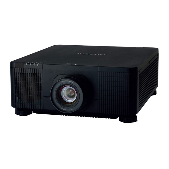
Projector parts and functions Projector parts and functions Front view Ventilation slot LED Indicator The hot air generated inside the projector is dispersed through the Infrared receiver ventilation slot. Make sure the ventilation slot is Lens free from obstruction. Ventilation inlet Adjustable foot The internal cooling fan draws cool air from the ventilation inlet into the... -
Page 18: Rear View
Projector parts and functions Rear view Projector Keypad Infrared sensor Power inlet Power switch Ventilation outlet ׀ -> on О -> off Adjustable foot Voltage Selector (Default at 115V) Adjustable foot IO Control Displays or hides the OSD adjustment screen. STANDBY/ON ▲... - Page 19 Projector parts and functions COMPUTER IN 2 Connects to five BNC inputs for PC (R/B/G/H/V) or for component (YPbPr) picture source and channel (Hs, Vs) source. COMPUTER IN 1 CONTROL Standard 15-pin VGA connection socket to connect to RGB, high-definition component input 9-pin D-sub socket.
-
Page 20: Bottom View
Projector parts and functions Bottom view 500,0 300,0 150,0 576,0 150,0 Mounting bracket screw hole These screw holes are used to mount the projector to its designated mounting bracket using 6 M4x16 screws. The dimensions of the screw holes are shown in the picture below. Adjustable foot Adjust the height and angle of the projector with the adjustable foot... -
Page 21: Range Of Effective Remote Control Signal Reception
Projector parts and functions Range of effective remote control signal reception The diagram below illustrates the range of effective remote control signal reception (Unused new battery). 40° 40° Note: Avoid placing the remote control at places of high temperature or humidity as it could cause the remote control to malfunction. -
Page 22: Installation The Projector
Installation of the Projector Installation the projector. 1. Orient the projector towards the screen Screen 2. Remove the lens PU foam on the projector Desk Top or Notebook CONTROL B/Cb/Pb R/Cr/Pr COMPUTER IN 1 3. Depending on your area, to select the correct input voltage. TRIGGER COMPUTER IN 2 Select 200-240V... -
Page 23: Starting The Projector Up
Installation of the Projector 6. Starting the projector up. Press the button on the projector or the button on the remote control to start up the projector. 7. Adjusting the projector's angle, Lens Shift, Zoom and Focus a. Please use the adjustable feet to change the angle of the projector in order to achieve the most suitable angle for projection on the screen. -
Page 24: Turning Off The Projector
Installation of the Projector The picture after adjust Fig 1 Focus Adjust Fig 3 Adjust Vertical Keystone Zoom Out Fig 4 Horizontal Keystone Zoom In 9. Turning off the projector STANDBY Press the button on the projector or the button on the remote control. The message will appear on the screen. -
Page 25: Throw Distance
Installation of the Projector Throw distance Throw Distance (TD) = Screen Width (W) x Throw Ratio (TR) Screen Width(W) Throw Distance(TD) Coupled with the available projection lenses, the projector offers the following throw ratios: • FL-920(FL-900) (0.32 : 1 100-350inch) •... -
Page 26: Front Ceiling
Installation of the Projector Front Ceiling Rear Ceiling Refer to " Page 31 : Front Ceiling " Refer to " Page 32 : Rear ceiling " Advantage: does not occupy floor space does not Advantage: the projector is completely hidden draw attention to it. -
Page 27: Horizontal And Vertical Lens Shift
Installation of the Projector Horizontal and vertical lens shift In addition to using the adjustable feet to adjust projection angle, you can also use the Lens Shift function to adjust the projected picture. Moving the lens vertically The distance of vertical lens movement is +60% , -22% of the screen height in both directions. For instance, if you are using a 2.15m ×... -
Page 28: Connecting The Projector To Other Devices
Installation of the Projector Connecting the projector to other devices HDMI / DVI connection Signals from picture source offer the best projection picture quality when sent through HDMI/DVI. Therefore, try to use input devices with HDMI/DVI output as the source of picture. CONTROL B/Cb/Pb R/Cr/Pr... -
Page 29: Rgb Connection
Installation of the Projector RGB connection Connect your PC or other devices with RGB output to the RGB input connectors on the projector to be used as the source of picture input. Desk Top or Notebook CONTROL R/Cr/Pr COMPUTER IN 1 B/Cb/Pb TRIGGER COMPUTER IN 2... -
Page 30: Sdi Connection
Installation of the Projector SDI connection This projector can be connected with other equipment that has SDI connector, but with some equipment the projector may not work properly. Use a cable of 5CFB or greater (5CFB, 7CFB, and so on), or Belden 1694A or greater to transmit the image properly. -
Page 31: Adjusting Screen Orientation
Installation of the Projector Adjusting screen orientation By default, the projector is configured for “Front Tabletop”. If you choose to install your projector in other setups, be sure to adjust the screen orientation to achieve the correct projection mode. MAIN Installation Front Tabletop ENTER... -
Page 32: Rear Ceiling
Installation of the Projector Rear ceiling → Advanced → Installation → Rear Ceiling and choose ON; the projector is now Press MENU configured for “Rear Ceiling”. Correct Picture Lotus Adjusting the projector lens Projector lens adjustment includes focus, zoom, horizontal/vertical picture shift. Please refer to " Page 23 : 7. -
Page 33: Remote Control
REMOTE CONTROL Remote control AUTO AUTO This button is used to turn on STANDBY This button is used to Resync the projector. the picture; when the picture STANDBY signal becomes unstable or picture quality deteriorates This button is used to turn off simply press this button and the projector. - Page 34 REMOTE CONTROL HDBaseT Remote control HDBaseT backlight Hotkeys to select the input source - HDBaseT. LED light FREEZE FREEZE Press this button to freeze the projected image. But Sound still keep going. Only effect image. STANDBY NUMBER KEY (0-9) Only availabel for ID Set when these button to be the FOCUS ZOOM PATTERN...
-
Page 35: Osd Menu Tree
OSD Menu description OSD Menu Tree 1st layer 2nd layer 3rd layer 4th layer Selections HDMI1 / HDMI2 Input COMPUTER IN 1 / COMPUTER IN 2 HDBaseT / SDI / DVI-D PinP On / Off HDMI1 / HDMI2 PinP Selection COMPUTER IN 1 / COMPUTER IN 2 HDBaseT / SDI / DVI-D Top Left / Top Right... - Page 36 OSD Menu description 1st layer 2nd layer 3rd layer 4th layer Selections Front Tabletop / Front Ceiling Installation Rear Tabletop / Rear Ceiling Zoom/Focus Lens Control Shift Memory 1 / Memory 2 Load Memory Memory 3 / Memory 4 Memory 5 Memory 1 / Memory 2 Lens Memory Save Memory...
- Page 37 OSD Menu description 1st layer 2nd layer 3rd layer 4th layer Selections Network Mode Projector Control / Service Standby Power On / Off DHCP On / Off IP Address xxx.xxx.xxx.xxx Network Subnet Mask xxx.xxx.xxx.xxx Gateway xxx.xxx.xxx.xxx xxx.xxx.xxx.xxx MAC Address xxx.xxx.xxx.xxx Top Left / Top Right Menu Position Bottom Left / Bottom Right...
-
Page 38: Osd Description
OSD Menu description OSD Description 1. Press the MENU button on the remote control or on the side of the projector to bring up the OSD Menu. 2. You will see six functional menus (Main, Picture, Laser, Advanced, Setup and Service). ▲... -
Page 39: Pinp
OSD Menu description PinP If you wish to display PinP picture (Picture in Picture), you can make the configuration here. By choosing "ON", you will see two windows on the projected picture; the larger one is the primary picture and the smaller one is the sub picture. By choosing "OFF", the PinP function will be disabled and you will only see a single picture window. -
Page 40: Color Space
OSD Menu description Color Space Select Color Space from the Advanced menu to choose the color space of the source signal for HDMI, COMPUTER IN, and component connections. The default setting, Auto, functions as follows: • Auto The Auto setting determines the correct color space to be used automatically. For HDMI input, this determination is based on the AVI infoframe conveying in the input signal. -
Page 41: Picture
OSD Menu description PICTURE MAIN Picture Mode Video Brightness PICTURE Contrast LASER Color ADVANCED Tint SETUP Sharpness SERVICE Noise Reduction Color Temperature 5400K White Balance ENTER Aspect Normal Over Scan Position and Phase ENTER Auto image Execute Picture Mode Use ◄► to select the display mode. •... -
Page 42: Contrast
OSD Menu description It is recommended that you adjust the picture to the following status: • The darkest black bar of the picture should disappear into the background. • The dark gray area should be barely visible. • The light gray area should be clearly visible. •... -
Page 43: Noise Reduction
OSD Menu description Noise Reduction Use ◄► to adjust the noise of the projected picture. This function is suitable for the elimination of picture noise from interleaving SD input. Generally speaking, reducing picture noise will lower the value of high frequency detail and make the picture appear more mellow. Refer to Fig 10. Fig 5 Fig 6 Fig 7... -
Page 44: Color Temperature
OSD Menu description Color Temperature You can choose from 5400K, 6500K, 7500K, 9300K and Native. Color temperature refers to the change in light color under different energies that is perceived by the naked eye. The change of color temperature from low to high for visible light goes from orange red → white →... -
Page 45: Aspect
OSD Menu description Aspect Use this function to adjust the aspect ratio of the projected picture. Use ▲ ▼ to adjust the ratio of picture length and width. The projector’s full picture size is 16:10 (1920×1200 dots).The following diagram illustrates the difference in various aspect ratio settings: Native input Output aspect ratio... -
Page 46: Over Scan
OSD Menu description Over Scan Due to the fact that some consumers may still be using older television systems, some TV programs may not display the edges of the picture. Use this function to hide the picture edge by choosing one of the following three options: •... -
Page 47: Auto Adjust
OSD Menu description • H Position Use ◄► to adjust the projected picture’s horizontal position. If the projected picture is not at the center of the screen (i.e. shifted to right or left) and ends up being cropped, use this function to adjust the picture’s horizontal position. The following picture is an example of test picture from an external signal source: Native picture Skewed... -
Page 48: Laser
OSD Menu description LASER MAIN Power Mode Custom Power Level PICTURE High Altitude Normal LASER ADVANCED SETUP SERVICE Power Mode • When set to Eco mode, the brightness will 80% of the normal brightness(Operature temperature must lower then 35°C. The cooling fan will auto slow down the speed. If the surrounding environment is sufficiently dark or if you do not require intense brightness, you can set the power mode to Eco to save the power. -
Page 49: High Altitude
OSD Menu description High Altitude Use this function to control the projector's cooling fan. You can set it to Off or On. The default setting is Off. Under normal circumstances, the projector will operate normally with this function set to Off. By default, the projector will detect the temperature of the surrounding environment to regulate the speed of the cooling fan. -
Page 50: Advanced
OSD Menu description ADVANCED MAIN Installation Front Tabletop Lens Control ENTER PICTURE Lens Memory ENTER LASER Lens Centering ENTER ADVANCED Gamma SETUP Pattern ENTER SERVICE Color Management ENTER ENTER Warping ENTER Blanking Edge Blending ENTER ENTER Memory Dynamic Black Installation Use these function to install the projection mode. -
Page 51: Lens Memory
OSD Menu description Lens Memory This projector can save 5 sets of lens position information (including Focus, Zoom and Lens shift setting). No matter how you adjust the lens , you can call these lens memory to restored the lens position setting that you record in the OSD. -
Page 52: Warping
OSD Menu description Warping The function provides distortion correction on projected pictures. • Keystone Press ▲ ▼◄► to correct horizontal keystone due to projection angle. Please refer to " Page 23 : 8. Correcting keystoning caused by projection angle " •... -
Page 53: Blanking
OSD Menu description • Bottom Left Corner Press ▲ ▼◄► to correct the bottom left picture bias. Refer to Fig 11. • Bottom Right Corner Press ▲ ▼◄► to correct the bottom right picture bias. Refer to Fig 11. Blanking •... - Page 54 OSD Menu description Level→ The outward boundaries of overlapping edges might appear brighter than the • Blending rest of the image due to the lumens at the inactive DMD display area. The purpose of Blending Level is compensate the non overlap area vs the overlap area. It increases the Blending Level of non overlap area .It is used to adjust the Blending Level at Top, Bottom, Left, Right directions on the projected pictures.
-
Page 55: Memory
OSD Menu description The picture below is an example if 2 projectors are projecting at the same picture. 1. Horizontally place two projectors and have the two projected pictures with an overlap area and use the focus/zoom and lens shift functions with test grid pattern to set a proper overlap area for blending with a matched grid size. ... -
Page 56: Setup
OSD Menu description SETUP MAIN Network ENTER OSD Settings ENTER PICTURE Infrared Remote LASER Remote ID ADVANCED Startup Logo SETUP Trigger Screen SERVICE Auto Search Auto Power Off Direct Power On Language English AMX D.D. Network • Network Mode Projector Control : Choice this fuction to control the projector via the web. Service : This function only for the professional service person. -
Page 57: Osd Setting
Note: This feature is disabled if the device is setting 00 to be the initial value. Start up logo You can use this function to have the projector display the HITACHI logo in the start up screen. Set to display the HITACHI logo during start up and to display a blank picture. -
Page 58: Auto Search
OSD Menu description Auto Search • By enabling this function, the projector will automatically determine the source of input every time it is turned on so that the user will not have to make the selection on the OSD Menu. •... -
Page 59: Service
OSD Menu description SERVICE MAIN Model Name LP-WU9750B Serial Number W529ZARCY0025 PICTURE Software Version 1 ME14v1-NA-FE09 LASER Software Version 2 LE07-14-RE02v1-3092 ADVANCED Actives Source DVI-D SETUP Signal Format ENTER SERVICE Laser Hours 00000 HRS Thermal Status ENTER Lens Infomation X-XXXXXX... -
Page 60: Laser Hours
OSD Menu description Laser Hours displays Laser module current usage time. When you notice the projected picture to be noticeably darker, please contact your local dealer. Thermal Status Display the thermal sensor current temperature, include Intake , DMD and Laser. Lens Information Lens Information Displays the lens ID and Lens name. -
Page 61: Cleaning
Cleaning Cleaning Turn off the projector and unplug the power before cleaning. Suggest to wait at least 45 minute to let the projector cool down. Cleaning the Cabinet • Use a dry soft cloth to wipe off the cabinet dust. Note: Not suggest to use cleanser. -
Page 62: Using The Kensington ® Lock
Kensington ® Using the Kensington Lock Worry about the security of the projector. You can use Kensington lock the projector to avoid it be stolen. Note: For Kensington lock detail installation inormation. Please contact to the dealer. -
Page 63: Simple Troubleshooting
Simple troubleshooting and definition of the LED indicators Simple troubleshooting The following table offers a list of common problems with projectors and how to troubleshoot. If the recommended solutions fail to resolve your problem, contact your local dealer to arrange for servicing; do not attempt to service the projector by yourself. - Page 64 Simple troubleshooting and definition of the LED indicators Problem Possible cause Solution 1. The temperature inside the projector might have 1. When the temperature inside the projector rises, risen. the cooling fan will operate at a higher speed to discharge the internal heat more rapidly. The noise from the cooling fan 2.
-
Page 65: Led Status
Simple troubleshooting and definition of the LED indicators LED STATUS Power LED LED Display Projector Status Procedure Power is off Green Projector warming up wait till projector start displaying Flashing wait until cooling finish ( ~ 10 sec) Orange Projector cooling Standby mode Green Projector is on... -
Page 66: Specifications
Projector specifications Specifications Specifications Description Resolution 1920 × 1200 (Native) Micro display 1 x 0.67" WUXGA DMD Contrast 1050:1(Native) / 20000:1 (Dynamic Black On) ≥ 90% Luminance uniformity Laser Diode: Lamp Green and Red by laser phosphor Blue by diffuse laser FL-920 (FL-900) (0.32 : 1 100-350inch) ML-904 (2.38~3.64 : 1 50-600inch) Projection lens - projection ratio... -
Page 67: Projector Specifications
Projector specifications Supported Signal Input Modes HDMI / HDBaseT Frame Signal H Freq. PCLK 5 BNC Resolution Rate DVI-D SDI/ Remark Format RGBHV RGBHV 8bit 10bit 12bit 640*480 31.469 59.94 25.175 VESA DMT 640*480 37.500 74.99 31.500 VESA DMT 640*480 43.269 36.000 VESA DMT... -
Page 68: Sdi Formats
Projector specifications SDI formats Color Sampling Timing SDI Link mode Signal Standards Bit Depth Encode Structure NTSC SMPTE 259M-C 270Mbps SD YCbCr 4:2:2 SMPTE 259M-C 270Mbps SD YCbCr 4:2:2 1035i60 SMPTE 292M 1.5Gbps HD YCbCr 4:2:2 1080i59 SMPTE 292M 1.5Gbps HD YCbCr 4:2:2 1080i60... -
Page 69: Dimensions
Projector specifications Dimensions 500mm... -
Page 70: Communication Settings
Communication settings Communication settings RS-232 Communication When the projector connects to the computer by RS-232 communication, the projector can be controlled with RS-232 commands from the computer. For details of RS-232 commands, refer to RS- 232 Communication command table. Connection 1. -
Page 71: Protocol
Communication settings 1. Protocol 19200bps,8N1 2. Command format ("h" shows hexadecimal) Byte Number Command Header Data Setting Header Data Action Type flag code size code Packet Action <SET>Change setting to desired value [(cL)(cH)] (aL) (aH) 01h 00h (bL) (bH) (cL) (cH) by [(bL)(bH)]. -
Page 72: Response Code / Error Code
Communication settings 3. Response code / Error code ("h" shows hexadecimal) 4. ACK reply : 06h When the projector receives the Set, Increment, Decrement or Execute , command correctly, the projector changes the setting data for the specified , item by [Type], and it returns the code. 5. -
Page 73: Connection
Communication settings Command Control via the Network When the projector connects network, the projector can be controlled with RS-232C commands from the computer with web browser. For details of RS-232C commands, refer to RS-232C Communication / Network command table. Connection Turn off the projector and the computer. -
Page 74: Command Control Settings
Communication settings Command control settings [TCP #23] 1. Command format Same as RS-232C communication, refer to RS-232C Communication command format. 2. Response code / Error code ("h" shows hexadecimal) Four of the response / error code used for TCP#23 are the same as RS-232C Communication (1)~(4). - Page 75 Communication settings Communication command table Hitachi Command Header Data (7 bytes) Command Data (6 bytes) Function Operation Description Header Setting Packet Data Size Action Type Code Code HDMI 1 BE EF 06 00 0E D2 01 00 00 20 03 00...
- Page 76 Communication settings Communication command table (continue) Hitachi Command Header Data (7 bytes) Command Data (6 bytes) Function Operation Description Header Setting Packet Data Size Action Type Code Code Increment BE EF 06 00 AE D7 04 00 10 30 00 00...
- Page 77 Communication settings Communication command table (continue) Hitachi Command Header Data (7 bytes) Command Data (6 bytes) Function Operation Description Header Setting Packet Data Size Action Type Code Code Increment BE EF 06 00 52 F4 04 00 B1 30 00 00...
- Page 78 Communication settings Communication command table (continue) Hitachi Command Header Data (7 bytes) Command Data (6 bytes) Function Operation Description Header Setting Packet Data Size Action Type Code Code Increment BE EF 06 00 96 92 04 00 01 24 00 00...
- Page 79 Communication settings Communication command table (continue) Hitachi Command Header Data (7 bytes) Command Data (6 bytes) Function Operation Description Header Setting Packet Data Size Action Type Code Code Increment BE EF 06 00 12 66 04 00 12 27 00 00...
- Page 80 Communication settings Communication command table (continue) Hitachi Command Header Data (7 bytes) Command Data (6 bytes) Function Operation Description Header Setting Packet Data Size Action Type Code Code Increment BE EF 06 00 FA 6B 04 00 2C 27 00 00...
- Page 81 Communication settings Communication command table (continue) Hitachi Command Header Data (7 bytes) Command Data (6 bytes) Function Operation Description Header Setting Packet Data Size Action Type Code Code Increment BE EF 06 00 FE DB 04 00 2C 30 00 00...
- Page 82 Communication settings Communication command table (continue) Hitachi Command Header Data (7 bytes) Command Data (6 bytes) Description Function Operation Header Setting Packet Data Size Action Type Code Code Increment BE EF 06 00 8A A2 04 00 AB 31 00 00...
- Page 83 Communication settings Communication command table (continue) Hitachi Command Header Data (7 bytes) Command Data (6 bytes) Description Function Operation Header Setting Packet Data Size Action Type Code Code Gateway BE EF 06 00 93 05 02 00 19 29 00 00...
- Page 84 Communication settings Communication command table (continue) Hitachi Command Header Data (7 bytes) Command Data (6 bytes) Function Operation Description Header Setting Packet Data Size Action Type Code Code Remote ID BE EF 06 00 AC 30 02 00 08 26...
- Page 85 Communication settings Communication command table (continue) Hitachi Command Header Data (7 bytes) Command Data (6 bytes) Function Operation Description Header Setting Packet Data Size Action Type Code Code DMD Temp. BE EF 06 00 94 03 02 00 53 4C...
- Page 86 PJLink command Commands Control Description Parameter or Response 0 = Standby POWR Power Control 1 = Power On 0 = Standby POWR ? Power Status inquiry 1 = Power On 2 = Cool Down 11 = COMPUTER IN 1 12 = COMPUTER IN 2 31 = HDMI 1 32 = DVI-D INPT...
- Page 87 Projector Name inquiry PROJECTOR NAME of the NETWORK menu Manufacturer's Name INF1 ? HITACHI inquiry LP-WU9750B INF2 ? Model Name inquiry INFO ? Other Information inquiry Responds with the factory information and so on CLSS ? Class Information inquiry 1 NOTE •...
-
Page 88: Copyright Information
Copyright information Copyright Copyright 2016. All rights reserved. No part of this publication may be reproduced, transmitted, transcribed, stored in a retrieva l system or translated into any language or computer language, in any form or by any means, electronic, mechanical, magnetic, optical, chemical, manual or otherwise, without the prior written permission of this company.
Need help?
Do you have a question about the LP-WU9750B and is the answer not in the manual?
Questions and answers