
Related Manuals for Hallde SB-4

Summary of Contents for Hallde SB-4
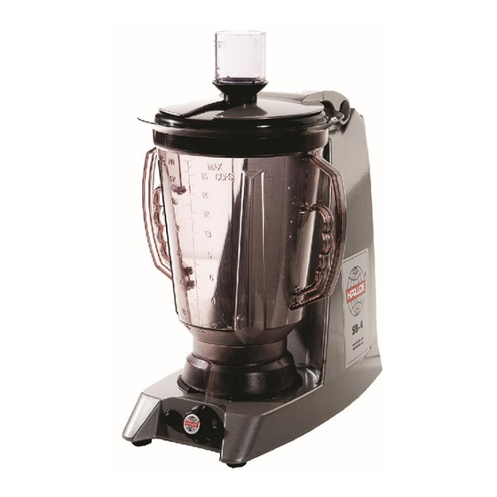
- Page 1 Service Manual Blender SB-4 100 – 240 V Single Phase Date: 2016-03-17 Approved: Henrik Artursson...
-
Page 2: Table Of Contents
Table of contents GENERAL ........................3 Installation, operation and cleaning..........................3 Tools....................................3 Lubrication and thread locking............................3 REMOVAL AND REPLACEMENT OF PART..............4 Knife unit and knives ............................... 4 Coupling and Drive Shaft..............................8 Power Cord..................................11 Micro switch..................................12 Camshaft..................................14 Knob pulse push button and speed control potentiometer .................. -
Page 3: General
This service manual gives instructions for removal and replacement of parts including service procedures and adjustments for the Blender SB-4 100 – 240 V single phase. This service manual is prepared for the use of trained service technicians and should not be used by those not properly qualified. -
Page 4: Removal And Replacement Of Part
Removal and replacement of part Knife unitand knives 1. Remove the jug from the machine. 2. Place the knife guard over the knives. 3. Hold the knife guard in place and turn the jug upside down. - Page 5 4. Undo the coupling by hand. 5. Using a torque wrench or a spanner, undo the nut that holds the knife unit.
- Page 6 6. Carefully push out the knife unit. 7. Place the knife guard over the knife unit.
- Page 7 8. Undo the domed nut that holds the knives in place. 9. Assemble in reverse order. Note! The orientation and position of the knives. Note! Tightening torque for domed nut that holds the knifes is 10 Nm (7.4 lb ft) and tightening torque for nut that looks the knife unit to the jug is 7 Nm (5.2 lb ft).
-
Page 8: Coupling And Drive Shaft
Note! Carefully position the knife unit using the notch on the jug. Notch Coupling and Drive Shaft Note! Disconnect the electric power to the machine! 1. Remove the screw, the screw is looked with Loctite and could be difficult to remove. - Page 9 2. Remove the coupling and washer. 3. Remove 4 feet with screw, one center screw and bottom plate from machine. 1x center screw 4x feet with screw...
- Page 10 4. Pull off the drive belt and remove three screws that hold the drive shaft. Drive belt 3x screw for drive shaft 5. Pull out the drive shaft. 6. Install the new drive shaft and assemble in reverse order. Tighten the drive belt as described under “Motor”.
-
Page 11: Power Cord
Power Cord Note! Disconnect the electric power to the machine! 1. Compress the cable retainer and carefully pull it from the back plate. 2. Remove two screws and pull out the back plate. -
Page 12: Micro Switch
3. Turn the machine on its side and pull out the back plate and circuit board. 4. Remove the lead wires from the circuit board. 5. Assemble in reverse order. Micro switch Note! Disconnect the electric power to the machine! 1. - Page 13 2. Turn the machine on its side and pull out the back plate and circuit board. 3. Remove wires from the micro switch. 4. Remove two screws and pull out the micro switch.
-
Page 14: Camshaft
5. Install the new micro switch, be careful to position the two notches in the right position. 2x notches 6. Assemble in reverse order. Camshaft Note! Disconnect the electric power to the machine! 1. Remove the micro switch as outlined in “Micro switch” 2. -
Page 15: Knob Pulse Push Button And Speedcontrol Potentiometer
3. Carefully push the camshaft out using a screwdriver. 4. Install the new camshaft from the right side of the machine. 5. Install the camshaft plug. 6. Install the micro switch and assemble in reverse order. Knob pulse push button and speedcontrol potentiometer Note! Disconnect the electric power to the machine! 1. - Page 16 3. Remove two screws and pull out the back plate. 4. Turn the machine on its side, disconnect the potentiometer and pulse push buttons wires from the circuit board.
- Page 17 5. Open the cable clips and pull out the wires to the potentiometer and pulse push button. Pulse push button Potentiometer 6. Remove the potentiometer. 7. Use a M10 spanner to the pulse push button. 8. Install new potentiometer and pulse push button and assemble in reverse order.
-
Page 18: Circuit Board
Circuit Board Note! Disconnect the electric power to the machine! 1. Remove two screws and pull out the back plate. 2. Turn the machine on its side, disconnect the wires from the circuit board. -
Page 19: Motor
3. Disconnect the circuit board from the back plate by compressing the four quick connectors. 4x quick connector 4. Install new circuit board and back plate in reverse order of assembly. Motor Note! Disconnect the electric power to the machine! 1. - Page 20 3. Remove drive belt, 4 screws and pull out motor with motor plate. 4x screw 4. Install motor in reverse order. 5. Attach the drive belt. Note! The drive belt must be properly aligned to the drive wheel. Aligne the drive belt properly...
- Page 21 6. Tighten the drive belt by pulling back the complete motor unit, do not tighten the drive belt to hard. The drive belt should flex 5 – 10 mm when pressed down. 7. Install bottom plate and screws in reverse order.
-
Page 22: Service Procedures And Adjustments
Service Procedures and Adjustments Electrical Control Test Procedures 1. Remove jug. 2. Remove the power supply plug from the wall socket. Check that the electrical cable is in good condition and has no cracks. A damaged electric cable must be replaced. 3. -
Page 23: Electrical Operation
Electrical Operation Component function Motor Drive motor Speed sensor Monitors speed of motor, the speed sensor is included in the motor Variable speed control Allows operator to set preferred speed Micro switch Keeps motor from turning ifjug is not installed properly Pulse push button Sets speed to maximum as long as the button... -
Page 24: Wiring Diagram
Circuit board Power cord Microswitch with bracket Wiring Diagram Please refer to user manual or www.hallde.com for wiring diagram. -
Page 25: Troubleshooting
Troubleshooting Note! To eliminate the risk of damage to the motor, the SB-4 is fitted with thermal motor protection that automatically switches off the machine if the temperature of the motor should become too high. The thermal motor protection has automatic reset, which means that the machine can be started again when the motor has cooled down, which usually takes between 10 and 30 minutes.
Need help?
Do you have a question about the SB-4 and is the answer not in the manual?
Questions and answers