Table of Contents
Advertisement
Quick Links
Advertisement
Table of Contents

Related Manuals for Patton electronics CopperLINK 2173


Summary of Contents for Patton electronics CopperLINK 2173
- Page 1 This is a Class A device and is not intended for use in a residential environment. Part# 07M2173-UM Rev. B Revised 8/31/10 An ISO-9001Certified Company USER MANUAL MODEL 2173 CopperLINK™ High Speed Ethernet Extender SALES OFFICE (301) 975-1000 TECHNICAL SUPPORT (301) 975-1007...
-
Page 2: Table Of Contents
A.7 Humidity ... 16 A.8 Dimensions ... 16 Model 2173 Series Factory Replacement Parts and Accessories... 17 Model 2173 Series Interface Pin Assignment ... 18 C.1 10/100Base-T Interface ... 18 RJ-45 ... 18 C.2 CopperLINK Interface ... 18 RJ-45 ... 18... - Page 3 Sample Rates/Distance Chart, Based on 24 AWG (0.5 MM) . 19...
-
Page 4: Warranty Information
1.0 WARRANTY INFORMATION Patton Electronics warrants all Model 2173 components to be free from defects, and will—at our option—repair or replace the product should it fail within one year from the first date of the shipment. This warranty is limited to defects in workmanship or materials, and does not cover customer damage, abuse or unauthorized modification. -
Page 5: Ce Declaration Of Conformity
tion. The device has been tested and found to comply with the limits for a Class A computing device in accordance with specifications in Subpart B of Part 15 of FCC rules, which are designed to provide reasonable pro- tection from such interference in a commercial installation. However, there is no guarantee that interference will not occur in a particular instal- lation. -
Page 6: Safety When Working With Electricity
• Do not open the device when the power cord is con- nected. For systems without a power switch and without an external power adapter, line voltages are present within the device when the power cord is connected. - Page 7 In accordance with the requirements of council direc- tive 2002/96/EC on Waste of Electrical and Electronic Equipment (WEEE), ensure that at end-of-life you sepa- rate this product from other waste and scrap and deliver to the WEEE collection system in your country for recy- cling.
-
Page 8: General Information
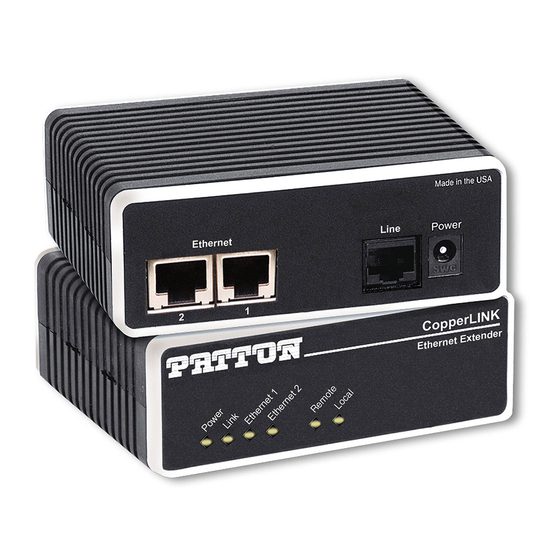
Operating in pairs, one Model 2173 is configured as the (L) Local unit located at one end of the LAN extension and the other Model 2173 is con- figured as the (R) Remote unit at the other end. The Model 2173 is config- ured as a L or R via the switch on the bottom of the unit. -
Page 9: Installation
The pair of 2173 models work together to create a transparent extension between two peered Ethernet LANs. Figure 1 shows a typical point-to- point application. The Interconnecting cables shall be acceptable for external use and shall be rated for the proper applica-... -
Page 10: Connecting The Twisted-Pair Line Interface
Follow the steps below to connect the Model 2173 CopperLINK Inter- faces. Note The Model 2173 units work in pairs. One of the units must be configured as a (L) Local unit, and the other unit must be config- ured as a (R) Remote unit. -
Page 11: Connecting The 10/100Base-T Ethernet Interface
19 (0.9mm) and 26 AWG (0.4mm). Leased circuits that run through signal equalization equipment are not acceptable. 2. The Model 2173 is equipped with an RJ-45 interface jack that can be used on the CopperLINK interface. The CopperLINK interface is a two-wire interface. -
Page 12: Connecting Power
An external AC or DC power supply is available separately. This connec- tion is made via the barrel jack on the rear panel of the Model 2173. No configuration is necessary for the power supply (See Appendix B for domestic and international power supply and cord options). - Page 13 Figure 6 on page 13 shows the orientation of the DIP switches in the On and Off positions. Front ™ Rear Switch toggle Push toggle up for ON position Push toggle down for OFF position Figure 6. DIP switch orientation 1 2 3 4...
-
Page 14: Configuring Dip Switch S1
No user settings required. This section describes reading the LED status monitors. 5.1 POWER UP Before applying power to the Model 2173, please review section 3.3, “Connecting Power” on page 12 to verify that the unit is connected to the appropriate power source. -
Page 15: Front Panel Led Status Monitors
5.2 FRONT PANEL LED STATUS MONITORS The Model 2173 features six front panel LEDs that monitor power, the Ethernet signals, the CopperLINK connection, and the remote/local set- ting. Figure 7 shows the front panel location of each LED. Table 2 on page 15 describes the LED functions. -
Page 16: Specifications
Two-wire unconditioned twisted pair. A.3 COPPERLINK LINE RATE AND COPPERLINK DISTANCE • Line Rate: Up to 155 Mbps aggregate (upstream/downstream) via Auto Rate; and 25/25 Mbps via DIP switch settings. • Distance: Up to 5,500 ft (1.6 km) Note Distances depend on line rate and line conditions. -
Page 17: Model 2173 Series Factory
Australian Power Cord 0805DEN Denmark Power Cord 0805FR France/Belgium Power Cord 0805IN India Power Cord 0805IS Israel Power Cord 0805JAP Japan Power Cord 0805SW Switzerland Power Cord *Only required with optional UI power supply (08055DCUI) APPENDIX B MODEL 2173 SERIES FACTORY Description... -
Page 18: Model 2173 Series Interface Pin Assignment
APPENDIX C MODEL 2173 SERIES INTERFACE PIN ASSIGNMENT C.1 10/100BASE-T INTERFACE RJ-45 • Pin 1: TX+ • Pin 2: TX- • Pin 3: RX+ • Pin 6: RX- • Pins 4, 5, 7, 8: no connection C.2 COPPERLINK INTERFACE RJ-45 •... - Page 19 SAMPLE RATES/DISTANCE CHART, BASED ON 24 AWG (0.5 MM) Rate Mode Fast Interleave 100/70 Fast 100/70 Interleave Interleave 25/25 50/50 Fast 50/50 Interleave 70/70 Fast 70/70 Interleave *. For the 25/25 rate, set S1-3 to the OFF position. Note The actual distance and link performance may vary depending on the environment and type/gauge of wire used.
- Page 20 Copyright © 2010. Patton Electronics Company All Rights Reserved.