Patton electronics CopperLink 2158 User Manual
Copperlink ethernet extender
Hide thumbs
Also See for CopperLink 2158:
- User manual (28 pages) ,
- User manual (28 pages) ,
- User manual (28 pages)
Table of Contents
Advertisement
Quick Links
Download this manual
See also:
User Manual
Advertisement
Table of Contents

Related Manuals for Patton electronics CopperLink 2158


Summary of Contents for Patton electronics CopperLink 2158
- Page 1 USER MANUAL MODEL 2158 CopperLink Ethernet Extender Part# 07M2158-B Doc# 058092UB Revised 6/7/02 An ISO-9001Certified Company...
-
Page 2: Table Of Contents
A.10 Humidity ..................14 A.11 Dimensions ................. 14 Model 2158 Series Factory Replacement Parts and Accessories........15 Model 2158 Series Interface Pin Assignment ......16 C.1 10/100Base-T Interface .............. 16 RJ-45 ..................16 C.2 CopperLink Interface ..............16 RJ-45 ..................16... -
Page 3: Warranty Information
The Model 2158 has been tested and found to comply with the limits for a Class A computing device in accordance with specifications in Sub- part B of Part 15 of FCC rules, which are designed to provide reasonable protection from such interference in a commercial installation. -
Page 4: Industry Canada Notice
1.4 SERVICE All warranty and non-warranty repairs must be returned freight prepaid and insured to Patton Electronics. All returns must have a Return Materi- als Authorization number on the outside of the shipping container. This number may be obtained from Patton Electronics Technical Services at: •... -
Page 5: General Information
LAN connections between peered Ethernet LANs, remote PC’s, or any other network enabled 10/100Base-T device. Operating in pairs, a Model 2158/L (local) located at one end of the LAN extension and a Model 2158/R (remote) at the other end, these units can automatically forward LAN broadcasts, multicasts, and frames across a 2- wire voice-grade twisted-pair link. - Page 6 Figure 1. Typical application The 2158/L and 2158/R work together to create a transparent extension between two peered Ethernet LANs. Figure 1 shows a typical point-to- point application.
-
Page 7: Installation
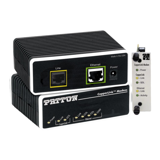
Figure 2. Model 2158 standalone rear panel 3.2 RACK CARD INSTALLATION The Model 2158 rack card version comprises a front card and a rear card. Do the following to install the cards into the rack chassis: 1. Slide the rear card into the back of the chassis along the metal rails. - Page 8 4. Secure the front card using the captive fasteners. Note The Model 1001R14 chassis supports “hot swapping” of cards, so it is not necessary to power down the rack when you install or remove a Model 2158 rack card. CopperLink RJ-45 interface CopperLink...
-
Page 9: Connecting The Twisted-Pair Line Interface
Note The Model 2158 units work in pairs. One of the units must be a Model 2158/L (Local), and the other unit must be a Model 2158/ R (Remote). The link is always initiated by the 2158/R. As long as the 2158/L is powered on, the 2158/R can establish a link by being powered on or by having its power reset. -
Page 10: Connecting The 10/100Base-T Ethernet Interface
Figure 6. Model 2158 10/100Base-T RJ-45 Connector Pinout. Connecting the 10/100Base-T Ethernet Port to a Hub The Model 2158 10/100Base-T interface is configured as DTE (Data Ter- minal Equipment), just like a 10/100Base-T network interface card in a PC. Therefore, it “expects” to connect to a 10/100Base-T Hub using a... -
Page 11: Connecting The 10/100Base-T Ethernet Port To A Pc (Dte)
3.5 CONNECTING POWER An external AC or DC power supply is available separately. This connec- tion is made via the barrel jack on the rear panel of the Model 2158. No configuration is necessary for the power supply (See Appendix B on page 15 for domestic and international power supply and cord options). -
Page 12: Operation
4.2 FRONT PANEL LED STATUS MONITORS The Model 2158 features five front panel LEDs that monitor power, the Ethernet signals, and the CopperLink connection. Figure 9 (standalone version) and Figure 10 on page 13 (rack card version) show the front panel location of each LED. - Page 13 Ethernet Link Ethernet Activity L i n i t y t i v Figure 10. Model 2158 rack card front panel Table 1: Front panel LED description Description Power Solid GREEN to indicate the unit is powered on. CopperLink Link...
-
Page 14: Specifications
APPENDIX A SPECIFICATIONS A.1 LAN CONNECTION • Shielded RJ-45, 10/100Base-T, IEEE 802.3 Ethernet • CopperLink Connection: RJ-45 and Terminal Block A.2 TRANSMISSION LINE Two-wire unconditioned twisted pair. A.3 COPPERLINK LINE RATE 12.5 Mbps, symmetric upstream/downstream. A.4 ACTUAL DATA RATE 10 Mbps, symmetric. A.5 COPPERLINK DISTANCE 4,000 ft (1,219 m) A.6 COPPERLINK SURGE SUPPRESSOR... -
Page 15: B Model 2158 Series Factory
(Local) 2158/R CopperLink Ethernet Extender; Line: RJ-45 & TB (Remote) 2158-2PK CopperLink Ethernet Extender Kit: includes one local (L) and one remote (R) Model 2158 2158RC/L Local Ethernet Extender, Rack Card 2158RC/R Remote Ethernet Extender, Rack Card 07M2158 User Manual... -
Page 16: Model 2158 Series Interface Pin Assignment
APPENDIX C MODEL 2158 SERIES INTERFACE PIN ASSIGNMENT C.1 10/100BASE-T INTERFACE RJ-45 • Pin 1: TX+ • Pin 2: TX- • Pin 3: RX+ • Pin 6: RX- • Pins 4, 5, 7, 8: no connection C.2 COPPERLINK INTERFACE RJ-45 •...
Need help?
Do you have a question about the CopperLink 2158 and is the answer not in the manual?
Questions and answers