Table of Contents
Advertisement
SPLIT-TYPE, HEAT PUMP AIR CONDITIONERS
SPLIT-TYPE, AIR CONDITIONERS
SERVICE MANUAL
Outdoor unit
[Model Name]
[Service Ref.]
PUZ-A18NHA6
PUZ-A18NHA6
PUZ-A24NHA6
PUZ-A24NHA6
PUZ-A30NHA6
PUZ-A30NHA6
PUZ-A36NHA6
PUZ-A36NHA6
PUZ-A42NHA6
PUZ-A42NHA6
PUZ-A18NHA6-BS
PUZ-A18NHA6-BS
PUZ-A24NHA6-BS
PUZ-A24NHA6-BS
PUZ-A30NHA6-BS
PUZ-A30NHA6-BS
PUZ-A36NHA6-BS
PUZ-A36NHA6-BS
PUZ-A42NHA6-BS
PUZ-A42NHA6-BS
PUY-A12NHA6
PUY-A12NHA6
PUY-A18NHA6
PUY-A18NHA6
PUY-A24NHA6
PUY-A24NHA6
PUY-A30NHA6
PUY-A30NHA6
PUY-A36NHA6
PUY-A36NHA6
PUY-A42NHA6
PUY-A42NHA6
PUY-A12NHA6-BS
PUY-A12NHA6-BS
PUY-A18NHA6-BS
PUY-A18NHA6-BS
PUY-A24NHA6-BS
PUY-A24NHA6-BS
PUY-A30NHA6-BS
PUY-A30NHA6-BS
PUY-A36NHA6-BS
PUY-A36NHA6-BS
PUY-A42NHA6-BS
PUY-A42NHA6-BS
PUZ-A24/30/36NHA6
PUY-A24/30/36NHA6
R410A
CONTENTS
1. REFERENCE MANUAL ································· 2
2. SAFETY PRECAUTION ································· 2
3. FEATURES ····················································· 6
4. SPECIFICATIONS ·········································· 7
5. DATA ······························································· 9
6. OUTLINES AND DIMENSIONS ··················· 13
7. WIRING DIAGRAM ······································ 16
8. WIRING SPECIFICATIONS ·························· 20
9. REFRIGERANT SYSTEM DIAGRAM ············· 23
10. TROUBLESHOOTING ·································· 26
11. EASY MAINTENANCE FUNCTION·············· 91
12. FUNCTION SETTING ··································· 95
14. DISASSEMBLY PROCEDURE ··················· 114
PARTS CATALOG (OCB577)
August 2015
No. OCH577
REVISED EDITION-A
Revision:
• Updated the table in
"1. REFERENCE MANUAL"
REVISED EDITION-A.
• Some descriptions have been
modified.
• Please void OCH577.
Notes:
• This manual describes service
data of the outdoor units only.
• RoHS compliant products have
<G> mark on the spec name
plate.
in
Advertisement
Table of Contents

Subscribe to Our Youtube Channel
Related Manuals for Mitsubishi PUZ-A18NHA6


Summary of Contents for Mitsubishi PUZ-A18NHA6
-
Page 1: Table Of Contents
SPLIT-TYPE, HEAT PUMP AIR CONDITIONERS SPLIT-TYPE, AIR CONDITIONERS August 2015 No. OCH577 SERVICE MANUAL R410A REVISED EDITION-A Outdoor unit [Model Name] [Service Ref.] Revision: PUZ-A18NHA6 PUZ-A18NHA6 • Updated the table in PUZ-A24NHA6 PUZ-A24NHA6 "1. REFERENCE MANUAL" PUZ-A30NHA6 PUZ-A30NHA6 REVISED EDITION-A. PUZ-A36NHA6 PUZ-A36NHA6 • Some descriptions have been PUZ-A42NHA6 PUZ-A42NHA6 modified. PUZ-A18NHA6-BS PUZ-A18NHA6-BS PUZ-A24NHA6-BS PUZ-A24NHA6-BS • Please void OCH577. PUZ-A30NHA6-BS PUZ-A30NHA6-BS... -
Page 2: Reference Manual
REFERENCE MANUAL INDOOR UNIT Model name Service Ref. Service manual No. PLA-A12/18/24/30/36/42BA6 PLA-A12/18/24/30/36/42BA6 OCH581 OCB581 PCA-A24/30/36/42KA6 PCA-A24/30/36/42KA6.TH OCH585 OCB585 PCA-A24/30/36KA4 PCA-A24/30/36KA4.TH OCH501 PCA-A42KA5 PCA-A42KA5.TH OCB501 PKA-A12/18HA6 PKA-A12/18HA6 OCH580 OCB580 PKA-A24/30/36KA6 PKA-A24/30/36KA6.TH OCH584 OCB584 PEA-A12/18AA6 PEA-A12/18AA6 HWE0807 PEAD-A24/30/36/42AA5 PEAD-A24/30/36/42AA5 HWE14030 SAFETY PRECAUTION 2-1. ALWAYS OBSERVE FOR SAFETY Before obtaining access to terminal, all supply circuits must be disconnected. - Page 3 2-2. CAUTIONS RELATED TO NEW REFRIGERANT Cautions for units utilizing refrigerant R410A Use a vacuum pump with a reverse flow check Use new refrigerant pipes. valve. In case of using the existing pipes for R22, be careful with Vacuum pump oil may flow back into refrigerant cycle and the following: that can cause deterioration of refrigerant oil, etc.
- Page 4 [1] Cautions for service (1) Perform service after recovering the refrigerant left in unit completely. (2) Do not release refrigerant in the air. (3) After completing service, charge the cycle with specified amount of refrigerant. (4) When performing service, install a filter drier simultaneously. Be sure to use a filter drier for new refrigerant.
-
Page 5: Low Ambient Cooling
2 Dimensions of flare cutting and flare nut The component molecules in HFC refrigerant are smaller compared to conventional refrigerants. In addition to that, R410A is a refrigerant, which has higher risk of leakage because its working pressure is higher than that of other refrig- erants. Therefore, to enhance air tightness and strength, flare cutting dimension of copper pipe for R410A has been specified separately from the dimensions for other refrigerants as shown below. The dimension B of flare nut for R410A also has partly been changed to increase strength as shown below. Set copper pipe correctly referring to copper pipe flaring dimensions for R410A below. For 1/2 and 5/8 inch pipes, the dimension B changes. Use torque wrench corresponding to each dimension. Dimension A Dimension B Flare cutting dimensions Flare nut dimensions Dimension A ( Nominal Outside Dimension B Nominal Outside -0.4 dimensions (in) diameter (mm) (in [mm]) R22 (mm) R410A dimensions (in) diameter (mm) (in [mm]) (mm) R410A 11/32-23/64 [ 9.1]... -
Page 6: Features
FEATURES PUZ-A18NHA6 PUZ-A24/30/36NHA6 PUZ-A18NHA6-BS PUZ-A24/30/36NHA6-BS PUY-A12/18NHA6 PUY-A24/30/36NHA6 PUY-A12/18NHA6-BS PUY-A24/30/36NHA6-BS PUZ-A42NHA6 PUZ-A42NHA6-BS PUY-A42NHA6 PUY-A42NHA6-BS CHARGELESS SYSTEM PRE-CHARGED REFRIGERANT IS SUPPLIED FOR PIPING LENGTH AT SHIPMENT. (Maximum 100 ft [30 m] (A42)/ Maximum 70 ft [21 m] (A12–36)) The refrigerant circuit with LEV(Linear Expansion Valve) and accumulator always control the optimal refrigerant level regardless of the length (A42: 100 ft [30 m] maximum/ A12–36: 70 ft [20 m] maximum and 16 ft [5 m] minimum) of piping. The additional refrigerant charging work during installation often causes problems. It is completely eliminated by chargeless system. This unique system improves the quality and reliability of the work done. -
Page 7: Specifications
SPECIFICATIONS Service Ref. PUZ-A18NHA6 PUZ-A24NHA6 PUZ-A30NHA6 PUZ-A36NHA6 PUZ-A42NHA6 PUZ-A18NHA6-BS PUZ-A24NHA6-BS PUZ-A30NHA6-BS PUZ-A36NHA6-BS PUZ-A42NHA6-BS Power supply Phase Single Cycle 60 Hz Voltage 208/230 V MOCP Breaker size External finish Munsell 3Y 7.8/1.1 Heat exchanger Plate fin coil Defrost method Reverse cycle... - Page 8 Service Ref. PUY-A12NHA6 PUY-A18NHA6 PUY-A24NHA6 PUY-A30NHA6 PUY-A36NHA6 PUY-A42NHA6 PUY-A12NHA6-BS PUY-A18NHA6-BS PUY-A24NHA6-BS PUY-A30NHA6-BS PUY-A36NHA6-BS PUY-A42NHA6-BS Power supply Phase Single Cycle 60 Hz Voltage 208/230 V MOCP Breaker size External finish Munsell 3Y 7.8/1.1 Heat exchanger Plate fin coil Defrost method Crankcase heater Compressor Hermetic Model...
-
Page 9: Data
– – – 1.7 kg 94 oz 100 oz 106 oz 109 oz 112 oz 115 oz 118 oz 121 oz 124 oz 127 oz 130 oz 133 oz 134.5 oz 136 oz 139 oz 142 oz 145 oz 148 oz 151 oz 154 oz 106 oz PUY-A24NHA6 PUZ-A18NHA6 56 oz 58 oz 60 oz 62 oz 64 oz 66 oz 60 oz PUY-A24NHA6-BS 2.7 kg 2.8 kg 3.0 kg 3.1 kg 3.2 kg 3.3 kg 3.3 kg 3.4 kg 3.5 kg 3.6 kg 3.7 kg 3.8 kg 3.8 kg 3.9 kg 3.9 kg 4.0 kg 4.1 kg 4.2 kg 4.3 kg 4.4 kg 3.0 kg... -
Page 10: Noise Criterion Curves
5-3. NOISE CRITERION CURVES PUY-A18NHA6 PUY-A12NHA6 PUY-A18NHA6-BS PUY-A12NHA6-BS SPL(dB) SPL(dB) MODE LINE MODE LINE PUZ-A18NHA6 COOLING COOLING PUZ-A18NHA6-BS HEATING NC-70 NC-70 NC-60 NC-60 NC-50 NC-50 NC-40 NC-40 NC-30 NC-30 APPROXIMATE APPROXIMATE THRESHOLD OF THRESHOLD OF HEARING FOR HEARING FOR NC-20... -
Page 11: Standard Operation Data
230 V 230 V 230 V 230 V 230 V Current 0.33 A 0.36 A 0.36 A 0.57 A 1.00 A 0.94 A Outdoor unit model PUZ-A18NHA6 PUZ-A24NHA6 PUZ-A30NHA6 PUZ-A36NHA6 PUZ-A42NHA6 Phase Single Single Single Single Single Cycle 60 Hz... -
Page 12: Cooling Only
5-4-2. Cooling only Representative matching PKA-A12HA6 PKA-A18HA6 PKA-A24KA6 PKA-A30KA6 PKA-A36KA6 PLA-A42BA6 Mode COOLING COOLING COOLING COOLING COOLING COOLING Total Capacity BTU/h 12 , 000 18 , 000 24 , 000 30 , 000 34 , 200 42 , 000 4 , 600 Input 1,190 2,240... -
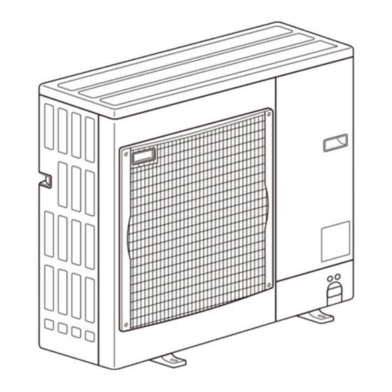
Page 13: Outlines And Dimensions
OUTLINES AND DIMENSIONS PUZ-A18NHA6 PUZ-A18NHA6-BS PUY-A12/18NHA6 PUY-A12/18NHA6-BS Unit: mm<in> 400<15-25/32> 347.5<13-11/16> {33<1-5/16> drain hole Air intake Air intake 45.4<1-25/32> Air discharge 4-oval hole 40<1-9/16> Service panel 18<23/32> 23<29/32> 22<7/8> Service panel for charge plug 2-{22.2<7/8> 1/2 conduit hole Connection for liquid pipe Handle FLARE {6.35<1/4>... - Page 14 PUZ-A24/30/36NHA6 PUZ-A24/30/36NHA6-BS PUY-A24/30/36NHA6 PUY-A24/30/36NHA6-BS Unit: mm<in> OCH577A...
- Page 15 PUZ-A42NHA6 PUZ-A42NHA6-BS PUY-A42NHA6 PUY-A42NHA6-BS Unit: mm<in> OCH577A...
-
Page 16: Wiring Diagram
WIRING DIAGRAM PUZ-A18NHA6 PUZ-A18NHA6-BS PUY-A12/18NHA6 PUY-A12/18NHA6-BS [LEGEND] SYMBOL NAME SYMBOL NAME SYMBOL NAME Terminal Block<Power Supply, Indoor/Outdoor> Converter LED1,LED2 LED<Operation Inspection Indicators> Motor for Compressor Power Module F1,F2,F3,F4 Fuse<T6.3AL250V> Fan Motor CB1,CB2,CB3 Main Smoothing Capacitor Switch<Pump Down> N.F. Noise Filter Circuit Board... - Page 17 PUZ-A24NHA6 PUZ-A24NHA6-BS PUY-A24NHA6 PUY-A24NHA6-BS [LEGEND] SYMBOL NAME SYMBOL NAME SYMBOL NAME Terminal Block<Power Supply, Indoor/Outdoor> TABU/V/W Switch<Function Switch> Connection Terminal<U/V/W-Phase> Motor for Compressor LED1,LED2 Converter LED<Operation Inspection Indicators> Fan Motor Power Module F1,F2,F3,F4 Fuse<T6.3AL250V> 21S4 Solenoid Valve (Four-Way Valve) CB1,CB2,CB3 Main Smoothing Capacitor Switch<Pump Down>...
- Page 18 PUZ-A30/36NHA6 PUZ-A30/36NHA6-BS PUY-A30/36NHA6 PUY-A30/36NHA6-BS [LEGEND] SYMBOL NAME SYMBOL NAME SYMBOL NAME Terminal Block<Power Supply, Indoor/Outdoor > P.B. Power Circuit Board Switch<Test Operation> Motor for Compressor TABU/V/W Switch<Model Select, Function Switch> Connection Terminal<U/V/W-Phase> Fan Motor TABS/T Connection Terminal<L1/L2-Phase> Switch<Model Select> 21S4 Solenoid Valve (Four-Way Valve) TABP1/P2 Connection Terminal<DC Voltage>...
- Page 19 PUZ-A42NHA6 PUZ-A42NHA6-BS PUY-A42NHA6 PUY-A42NHA6-BS [LEGEND] SYMBOL NAME SYMBOL NAME SYMBOL NAME Terminal Block<Power Supply, Indoor/Outdoor > P.B. Power Circuit Board Switch<Test Operation> Motor for Compressor TABU/V/W Connection Terminal<U/V/W-Phase> Switch<Model Select, Function Switch> MF1,MF2 Fan Motor TABS/T Connection Terminal<L1/L2-Phase> Switch<Model Select> 21S4 Solenoid Valve (Four-Way Valve) TABP1/P2/P...
-
Page 20: Wiring Specifications
WIRING SPECIFICATIONS 8-1. INDOOR UNIT POWER SUPPLIED FROM OUTDOOR UNIT (A-control application) The following connection patterns are available. The outdoor unit power supply patterns vary on models. 1:1 System Simultaneous twin system A Outdoor unit power supply B Wiring circuit breaker or isolating switch C Outdoor unit D Indoor unit/outdoor unit connecting cords E Remote controller... -
Page 21: Specifications
8-2. SEPARATE INDOOR UNIT/OUTDOOR UNIT POWER SUPPLIES The following illustrations show available connection patterns. The outdoor unit power supply patterns vary on models. 1:1 System The optional indoor power supply terminal kit is required. Outdoor unit power supply Wiring circuit breaker or isolating switch Outdoor unit Indoor unit/outdoor unit connecting cords Remote controller... - Page 22 8-3. INDOOR - OUTDOOR CONNECTING CABLE Wire No. o Size Outdoor power supply Max. 147 ft [45 m] Max. 164 ft [50 m] Max. 262 ft [80 m] Indoor unit-Outdoor unit 3 o AWG16(polar) 3 o AWG13(polar) 3 o AWG13(polar) and S3 separated Note: The maximum cable length may vary depending on the condition of installation, humidity or materials, etc.
-
Page 23: Refrigerant System Diagram
REFRIGERANT SYSTEM DIAGRAM PUZ-A18NHA6 PUZ-A18NHA6-BS Unit: mm (in) <4-way valve solenoid coil> Heating : ON High pressure Service Stop valve protect switch port(check) (with service port) Cooling : OFF 4-way valve Outdoor heat exchanger (#50) Refrigerant GAS pipe Strainer Thermistor 12.7A({1/2) (TH6) Muffler Thermistor (TH3) Thermistor Thermistor... - Page 24 PUY-A12NHA6 PUY-A12NHA6-BS PUY-A18NHA6 PUY-A18NHA6-BS Unit: mm (in) Service port Stop valve High pressure (Check) (with service port) protect switch Outdoor heat exchanger (#50) Thermistor Strainer Refrigerant GAS pipe (TH6) 12.7A({1/2) Thermistor (TH3) Thermistor Thermistor (TH32) (TH33) Distributor Accumulator Refrigerant flow in cooling Compressor (#100) (#100)
- Page 25 1. Refrigerant collecting (pump down) Perform the following procedures to collect the refrigerant when moving the indoor unit or the outdoor unit. 1 Supply power (circuit breaker). • When power is supplied, make sure that “CENTRALLY CONTROLLED” is not displayed on the remote controller. If “CENTRALLY CONTROLLED” is displayed, the refrigerant collecting (pump down) cannot be completed normally. • Start-up of the indoor-outdoor communication takes about 3 minutes after the power (circuit breaker) is turned on. Start the pump-down operation 3 to 4 minutes after the power (circuit breaker) is turned ON. 2 After the liquid stop valve is closed, set SW1-1 on the control board of the outdoor unit to ON. The compressor (outdoor unit) and ventilators (indoor and outdoor units) start operating and refrigerant collecting operation begins. LED1 and LED2 on the control board of the outdoor unit are lit. • O nly set SW1-1 to ON if the unit is stopped. However, even if the unit is stopped and SW1-1 is set to ON less than three minutes after the compressor stops, the refrigerant collecting operation cannot be performed. Wait until compressor has been stopped for three minutes and then set SW1-1 to ON again. 3 Because the unit automatically stops in about two to three minutes when the refrigerant collecting operation is completed (LED1 off, LED2 lit), be sure to quickly close the gas stop valve. If LED1 is lit and LED2 is off and the outdoor unit is stopped, refrigerant collection is not properly performed. Open the liquid stop valve completely, and then repeat step 2 after three minutes have passed. • I f the refrigerant collecting operation has been completed normally (LED1 off, LED2 lit), the unit will remain stopped until the power supply is turned off. 4 Turn off the power supply (circuit breaker). • Note that when the extension piping is very long with large refrigerant amount, it may not be possible to perform a pump-down operation. Warning: When pumping down the refrigerant, stop the compressor before disconnecting the refrigerant pipes. The compressor may burst if air etc.
-
Page 26: Troubleshooting
TROUBLESHOOTING 10-1. TROUBLESHOOTING <Check code displayed by self-diagnosis and actions to be taken for service (summary)> Present and past check codes are logged, and they can be displayed on the wired remote controller and control board of out- door unit. Actions to be taken for service, which depends on whether or not the trouble is reoccurring in the field, are summa- rized in the table below. Check the contents below before investigating details. Unit conditions at service Check code Actions to be taken for service (summary) Judge what is wrong and take a corrective action according Displayed to “10-4. - Page 27 10-2-1. Test run for wired remote controller <PAR-30MAA> <PAR-31MAA> MENU RETURN SELECT ON/OFF Function buttons Select "Service" from the Main menu, and press the button. Test run Input maintenance info. Function setting Check Self check Select "Test run" with the F1 or F2 button, and press the button. Select "Test run" with the F1 or F2 button, and press the button. Test run menu Test run Drain pump test run Service menu:...
-
Page 28: Error Information
<Error information> When an error occurs, the following screen will appear. Check the error status, stop the operation, and consult your dealer. C heck code, error unit, refrigerant address, unit model name, and serial Error information number will appear. Error code The model name and serial number will appear only if the information has Error unit Ref. - Page 29 <Checking the error information> Main Main menu Restriction While no errors are occurring, page 2/2 of the error information can be viewed by Energy saving selecting "Error information" from the Main menu. Night setback Errors cannot be reset from this screen. Filter information Error information Main display: Cursor Page blinks <Error history> Test run Input maintenance info. S elect "Service" from the Main menu, and press the button. Function setting Check Self check Select "Check" with the F1 or F2 button, and press the button.
- Page 30 Test run [for IR wireless remote controller] Measure an impedance between the power supply terminal block on the outdoor unit and ground with a 500 V Megger and check that it is equal to or greater than 1.0 M". TEST COOL 1 Turn on the main power to the unit. TEST RUN 2 Press the button twice continuously. (Start this operation from the turned off status of remote controller display.) and current operation mode are displayed. TEST RUN TEMP ON/OFF MODE 3 Press the ( ) button to activate mode, then COOL check whether cool air blows out from the unit. MODE 4 Press the ( ) button to activate mode, then HEAT check whether warm air blows out from the unit. AUTO STOP 5 Press the button and check whether strong air blows out AUTO START MODE VANE from the unit. VANE 6 Press the button and check whether the auto vane operates CHECK LOUVER properly.
- Page 31 10-3. HOW TO PROCEED "SELF-DIAGNOSIS" 10-3-1. Self-diagnosis <PAR-30MAA> <PAR-31MAA> Test run Input maintenance info. Function setting Check S elect "Service" from the Main menu, and press the button. Self check Select "Self check" with the F1 or F2 button, and press the button. W ith the F1 or F2 button, enter the refrigerant address, and press the button. Ref. address C heck code, unit number, attribute will appear. "-" will appear if no error history is available. Ref.
- Page 32 10-3-2. Remote controller check <PAR-30MAA> <PAR-31MAA> If operations cannot be completed with the remote controller, diagnose the remote controller with this function. S elect "Service" from the Main menu, and press the button. Maintenance password Remote controller check Select "Remote controller check" with the F1 or F2 button, and press button. S elect "Remote controller check" from the Service menu, and press the but- Remote controller check ton to start the remote controller check and see the check results. Start checking? To cancel the remote controller check and exit the "Remote controller check" menu screen, press the or the button.
- Page 33 10-4. SELF-DIAGNOSIS ACTION TABLE <Abnormalities detected when the power is turned on> Note: Refer to indoor unit section for code P and code E. Abnormal point and detection method Judgment and action Check code Case 1 No voltage is supplied to terminal 1 Check following items. block (TB1) of outdoor unit. a) Power supply breaker a) Power supply breaker is b) Connection of power supply terminal block turned off. (TB1) b) Contact failure or disconnec- c) Connection of power supply terminal block tion of power supply terminal (TB1) c) Open phase (L1 or L2 phase) 2 Electric power is not charged to 2 Check following items. power supply terminal of out- a) Connection of power supply terminal block door power circuit board.
- Page 34 Abnormal point and detection method Case Judgment and action Check code 63H connector open 1 Disconnection or contact failure 1 Check connection of 63H connector on Abnormal if 63H connector circuit is open for of 63H connector on outdoor outdoor controller circuit board. 3 minutes continuously after power supply. controller circuit board Refer to "10-9. TEST POINT DIAGRAM". 63H: High-pressure switch 2 Disconnection or contact failure 2 Check the 63H side of connecting wire. of 63H (5201) 3 63H is working due to defective 3 Check continuity by tester. parts. Replace the parts if the parts are defective. 4 Defective outdoor controller 4 Replace outdoor controller circuit board. circuit board Miswiring of indoor/outdoor unit 1 Contact failure or miswiring of 1 Check disconnection or looseness or polarity of indoor/outdoor unit connecting wire of indoor/outdoor unit connecting connecting wire...
-
Page 35: Cooling
<Abnormalities detected while unit is operating> Abnormal point and detection method Judgment and action Check code Case High pressure (High-pressure switch 1–6 C heck indoor unit and repair the defect. 1 Short cycle of indoor unit 63H operated) 2 Clogged filter of indoor unit Abnormal if high-pressure switch 63H 3 Decreased airflow caused by worked (*) during compressor operation. dirt of indoor fan *602 PSIG [4.15 MPa] 4 Dirt of indoor heat exchanger 5 Locked indoor fan motor 63H: High-pressure switch 6 Malfunction of indoor fan motor 7 Defective operation of stop 7 Check if stop valve is fully open. valve (Not full open) 8 Clogged or broken pipe 8 Check piping and repair the defect. - Page 36 Abnormal point and detection method Judgment and action Check code Case Open/short circuit of outdoor unit 1 Disconnection or contact failure 1 Check connection of connector (TH32) on the outdoor controller circuit board. Check break- temperature thermistor (TH32) of connectors (TH32) on ing of the lead wire for TH32. Refer to "10-9. Abnormal if open (37˚F [3:] or less) or the outdoor controller circuit TEST POINT DIAGRAM". short (422˚F [217:] or more) is detected board during compressor operation. 2 Check resistance value of TH32 or 2 Defective thermistor temperature by microprocessor. (Detection is inoperative for 10 minutes 3 Defective outdoor controller (Thermistor/TH32: Refer to "10-6. HOW TO (5104) of compressor starting process and for 10 circuit board CHECK THE PARTS".) (SW2 on A-Control minutes after and during defrosting.) Service Tool: Refer to "10-10. FUNCTION TH32: Thermistor <Comp. surface>...
- Page 37 Abnormal point and detection method Judgment and action Check code Case Outdoor fan motor 1 Check or replace DC fan motor. 1 Failure in the operation of the Abnormal if the rotational frequency of fan DC fan motor motor is not detected during DC fan motor 2 Check the voltage of the outdoor circuit 2 Failure in the outdoor circuit operation. controller board during operation. controller board Fan motor rotational frequency is abnor- 3 Replace outdoor controller circuit board. mal if; (when the failure is still indicated even (4400) • 1 00 rpm or below detected continuously after performing the action 1 above.) for 15 seconds at 68˚F [20:] or more outside air temperature. • 5 0 rpm or below or 1500 rpm or more detected continuously for 1 minute. To find out the detail history (latest) about U9 error, turn ON SW2-1, 2-2 and 2-6. Detailed codes Refer to "10-10. FUNCTION OF SWITCHES, CONNECTORS AND JUMPERS".
- Page 38 Check Code Abnormal point and detection method Case Judgment and action PFC/IGBT error Detailed 1 Incorrect switch settings on the 1 Correction of a model select codes (Undervoltage) outdoor controller circuit board • When compressor is running, for model select DC bus voltage stays at 310 V 2 Defective outdoor power circuit 2 Replace outdoor power circuit board. (4220) or lower for consecutive 10 board seconds 3 Defective outdoor controller 3 Replace outdoor controller circuit board. circuit board Compressor overcurrent interruption 1 Stop valve is closed. 1 Open stop valve. (When compressor locked) 2 Decrease of power supply voltage 2 Check facility of power supply.
- Page 39 Abnormal point and detection method Judgment and action Check code Case Remote controller transmission error 1 Contact failure at transmission 1 Check disconnection or looseness of indoor unit or transmission wire of remote controller. (E0)/signal receiving error (E4) wire of remote controller 2 Set one of the remote controllers “main”. 1 Abnormal if main or sub remote control- 2 All remote controllers are set If there is no problem with the action above. ler cannot receive normally any trans- as “sub” remote controller. In 3 Check wiring of remote controller. mission from indoor unit of refrigerant this case, E0 is displayed on • Total wiring length: max. 500 m [1640ft] address “0” for 3 minutes. remote controller, and E4 is (Do not use cable o 3 or more.) (Check code : E0) displayed at LED (LED1, LED2) • The number of connecting indoor units: on the outdoor controller circuit 2 Abnormal if sub-remote controller could max. 16 units not receive for any signal for 2 minutes.
- Page 40 Abnormal point and detection method Judgment and action Case Check code Indoor/outdoor unit communication 1 Check disconnection or looseness of indoor/ 1 Contact failure of indoor/out- outdoor unit connecting wire of indoor or out- error (Signal receiving error) door unit connecting wire door units. (Outdoor unit) 2 Defective communication circuit 2–4 Turn the power off, and on again to (1) Abnormal if outdoor controller circuit of outdoor controller circuit board check. Replace indoor controller board or board could not receive anything nor- 3 Defective communication circuit outdoor controller circuit board if abnormal- mally for 3 minutes. of indoor controller board ity is displayed again. 4 Noise has entered into indoor/ outdoor unit connecting wire. (6840) Indoor/outdoor unit communication 1 Indoor/outdoor unit connecting 1 Check disconnection or looseness of indoor/...
- Page 41 Abnormal point and detection method Judgment and action Check code Case 1 Slight temperature difference Pipe temperature 1–4 Check pipe <liquid or condenser/ between indoor room evaporator> temperature with room <Cooling mode> temperature and pipe <liquid temperature display on remote Detected as abnormal when the pipe tem- or condenser/evaporator> controller and outdoor controller circuit perature is not in the cooling range 3 min- temperature thermistor utes after compressor start and 6 minutes board. • Shortage of refrigerant after the liquid or condenser/evaporator pipe Pipe <liquid or condenser/evaporator> • Disconnected holder of is out of cooling range. temperature display is indicated by pipe <liquid or condenser/ Note 1: It takes at least 9 minutes to detect. setting SW2 of outdoor controller circuit evaporator> thermistor Note 2: Abnormality P8 is not detected in board as follows. • Defective refrigerant circuit drying mode.
- Page 42 Check code Abnormal point and detection method Case Judgment and action Communication error with communica- Turn off the power supply of outdoor unit and 1 Data of transmission proces- sor or unit processor is not indoor unit and FRESH MASTER or LOSSNAY tion processor transmitted normally because at the same time for 2 minutes or more, and Defective communication between unit of accidental trouble such as turn the power on again. System returns to processor and transmission processor noise or lightning surge. normal if abnormality was accidental malfunc- Note: The address and attribute display at tion. If the same abnormality generates again, 2 Address forwarding from unit remote controller indicate the con- processor is not transmitted abnormality-generated controller may be defec- (6606) troller that detected abnormality. normally because of defective tive. transmission processor hard- ware.
- Page 43 From the previous page. Check code Abnormal point and detection method Judgment and action Case 4. If displayed address or attribute is Same as mentioned in “A7” of the previous 1 During group operation with remote controller, page. indoor unit of multi- refrigerant Indoor unit detects abnormality when system, if indoor unit transmit to remote controller while out- indoor unit transmitted to remote control- door unit power supply of one ler and there was no reply (ACK). refrigerant system is turned off or within 2 minutes of restart, abnormality is detected. 2 Contact failure of transmission wire of remote controller or indoor unit 3 Disconnection of transmission connector (CN2M) of indoor unit 4 Defective transmitting receiving circuit of indoor unit or remote controller 5. If displayed address or attribute is...
- Page 44 Check code Abnormal point and detection method Case Judgment and action M-NET NO RESPONSE 1 Transmitting condition is 1 Check transmission waveform or noise on repeated fault because of Abnormal if a message was transmitted transmission wire. noise and the like. and there were reply (ACK) that message 2 Turn off the power supply of outdoor unit was received, but response command 2 Extension of transmission wire and indoor unit and FRESH MASTER or voltage and signal is caused does not return. Transmitting side detects LOSSNAY at the same time for 2 minutes or by over-range transmission abnormality every 30 seconds, 6 times more, and turn the power on again. If mal- wire. continuously. function was accidental, the unit returns to • Maximum distance · ····· 656 ft Note: The address and attribute displayed normal. If the same abnormality generates [200 m] at remote controller indicate the con- again, controller of displayed address and...
- Page 45 Factor Phenomena Countermeasure 4. Even controlling by the IR wireless 1 T he pair number settings of the IR wireless 1 Check the pair number settings. remote controller no beep is heard remote controller and indoor controller board are and the unit does not start operat- mismatched. ing. Operation display is indicated on IR wireless remote controller. 5. When operating by the IR wireless 1 N o operation for 2 minutes at most after the power 1 Normal operation remote controller, beep sound is supply ON. heard, however, unit does not start 2 Hand-held remote controller operation is prohibited. 2 Normal operation operating. • R emote controlling adaptor is connected to CN32 on the indoor controller board. • H and-held remote controller operation is prohibited by centralized controller etc. since it is connected to MELANS. 3 R efer to factor of phenomena No.2 on previous 3 C heck the details of phenomena No.2 on page.
- Page 46 Symptoms: “PLEASE WAIT” is kept being displayed on the remote controller. Inspection method and Diagnosis flow Cause troubleshooting Check the display time of “PLEASE WAIT” after turning on the main power. 6 minutes 2 minutes or more or less How long is “PLEASE WAIT” •...
- Page 47 LED display of the indoor controller board LED1 : Symptoms: Nothing is displayed on the remote controller. 1 LED2 : LED3 : Inspection method and Diagnosis flow Cause troubleshooting Check the voltage between S1 and S2 on the terminal block (TB4) of the indoor unit.
- Page 48 LED display of the indoor controller board LED1 : Symptoms: Nothing is displayed on the remote controller. 2 LED2 : LED3 : Inspection method and Diagnosis flow Cause troubleshooting Check the voltage between S1 and S2 on the terminal block (TB4) of the indoor unit.
- Page 49 LED display of the indoor controller board LED1 : Symptoms: Nothing is displayed on the remote controller. 3 LED2 : LED3 : — Inspection method and Diagnosis flow Cause troubleshooting Check the voltage of the terminal block (TB6) of the remote controller. •...
- Page 50 • Before repair Frequent calling from customers Phone Calls From Customers How to Respond Note Unit does 1 The operating display of remote 1 Check if power is supplied to air conditioner. not operate controller does not come on. Nothing appears on the display unless power is at all.
- Page 51 Phone Calls From Customers How to Respond Note The room cannot be cooled or heated sufficiently. 1 Check the set temperature of remote controller. The outdoor unit cannot be operated if the set temperature is not appropriate. The outdoor unit operates in the following modes. COOL: When the set temperature is lower than the room temperature.
- Page 52 Phone Calls From Customers How to Respond Note However, this control is also Something 3 Air blows out for a while after 3 This is not a malfunction. is wrong HEAT operation is stopped. The blower is operating just for cooling down the applied to the models which with the heated-up air conditioner.
- Page 53 Phone Calls From Customers How to Respond Note A white mist is expelled from the indoor unit. This is not a malfunction. This may occur when the operation gets started in the room of high humidity. Water or moisture is expelled from the outdoor COOL: when pipes or piping joints are cooled, they unit.
- Page 54 10-6. HOW TO CHECK THE PARTS PUZ-A18/24/30/36/42NHA6 PUZ-A18/24/30/36/42NHA6-BS PUY-A12/18/24/30/36/42NHA6 PUY-A12/18/24/30/36/42NHA6-BS Parts name Check points Thermistor (TH3) Disconnect the connector then measure the resistance with a tester. <Liquid> (At the ambient temperature 50 to 86°F [10 to 30:]) Thermistor (TH6) < 2-phase pipe> Normal Abnormal Thermistor (TH7)
- Page 55 10-6-1. Check method of outdoor controller circuit board PUZ-A18/24/30/36/42NHA6 PUZ-A18/24/30/36/42NHA6-BS PUY-A12/18/24/30/36/42NHA6 PUY-A12/18/24/30/36/42NHA6-BS Outdoor controller circuit board check Fuse check Check the fuse on outdoor controller circuit board. Yes (blow) Did the fuse (F1 and F2) blow? Check the indoor controller board wiring. Yes (blow) Did the fuse (F3 and F4) blow? Check the wiring for SV1 and 21S4.
- Page 56 10-6-2. Check method of noise fi lter circuit board PUZ-A18NHA6 PUZ-A18NHA6-BS PUY-A12/18NHA6 PUY-A12/18NHA6-BS Noise filter circuit board check Note: To check the voltage of the parts on this board with a tester is difficult due to its location. Test points are limited.
- Page 57 10-6-3. Check method of noise fi lter circuit board PUZ-A24NHA6 PUZ-A24NHA6-BS PUY-A24NHA6 PUY-A24NHA6-BS Noise filter circuit board check Note: To check the voltage of the parts on this board with a tester is difficult due to its location. Test points are limited. Is the voltage of main incoming power •...
- Page 58 10-6-4. Check method of noise filter circuit board PUZ-A30/36/42NHA6 PUZ-A30/36/42NHA6-BS PUY-A30/36/42NHA6 PUY-A30/36/42NHA6-BS Noise filter circuit board check Note: To check the voltage of the parts on this board with a tester is difficult due to its location. Test points are limited. Is the voltage of main incoming power •...
- Page 59 10-6-5. Check method of power circuit board PUZ-A18/24NHA6 PUZ-A18/24NHA6-BS PUY-A12/18/24NHA6 PUY-A12/18/24NHA6-BS Power circuit board check Note: To check the voltage of the parts on this board with a tester is difficult due to its location. Test points are limited. Is the voltage of main incoming power •...
-
Page 60: Noise
10-6-6. Check method of power circuit board PUZ-A30/36/42NHA6 PUZ-A30/36/42NHA6-BS PUY-A30/36/42NHA6 PUY-A30/36/42NHA6-BS Power circuit board check Note: To check the voltage of the parts on this board with a tester is difficult due to its location. Test points are limited. Is the voltage of main incoming power •... -
Page 61: Noise
10-6-7. Check method of ACTM PUZ-A30/36/42NHA6 PUZ-A30/36/42NHA6-BS PUY-A30/36/42NHA6 PUY-A30/36/42NHA6-BS ACTM check Note: To check the voltage of the parts on this board with a tester is difficult due to its location. (Active Filter Module) Test points are limited. Is the voltage of main incoming power •... - Page 62 10-6-8. Check method of DC fan motor (fan motor/ outdoor controller circuit board) Notes · High voltage is applied to the connecter (CNF1, 2) for the fan motor. Pay attention to the service. · Do not pull out the connector (CNF1, 2) for the motor with the power supply on. (It causes trouble of the outdoor controller circuit board and fan motor.) Self check...
- Page 63 10-7. HOW TO CHECK THE COMPONENTS <Thermistor feature chart> Low temperature thermistors • Thermistor <Liquid> (TH3) • Thermistor <2-phase pipe> (TH6) • Thermistor <Ambient> (TH7) • Thermistor <Suction> (TH33) Thermistor R0 = 15 k" ± 3% B constant = 3480 ± 2% =15exp{3480( 273+t – 273 )} t (:): R =15exp{3480( 273+(T– 32)/1.8 – 273 )} T (˚F): R 32˚F [0:] 15 k" 86˚F [30:] 4.3 k" 50˚F [10:] 9.6 k" 104˚F [40:] 3.0 k" 68˚F [20:] 6.3 k" 77˚F [25:] 5.2 k"...
-
Page 64: Ground
Linear expansion valve (A12, 18) (1) Operation summary of the linear expansion valve • Linear expansion valve opens/closes through stepping motor after receiving the pulse signal from the outdoor controller board. • Valve position can be changed in proportion to the number of pulse signal. <Connection between the outdoor controller board and the linear expansion valve> Outdoor controller board 12 V DC Drive circuit Brown Blue Orange Yellow White Connector LEV-A <Output pulse signal and the valve operation> Output Output (Phase) Opening a valve : 8 → 7 → 6 →5 → 4 → 3 → 2 → 1 → 8 Closing a valve : 1 → 2 → 3 → 4 → 5 → 6 → 7 → 8 → 1 The output pulse shifts in above order. -
Page 65: Ground
Linear expansion valve (A24, 30, 36, 42) (1) Operation summary of the linear expansion valve • Linear expansion valve opens/closes through stepping motor after receiving the pulse signal from the outdoor controller board. • Valve position can be changed in proportion to the number of pulse signal. <Connection between the outdoor controller board and the linear expansion valve> Outdoor controller board DC12V Gray Drive circuit Orange Yellow Black Connector LEV-A <Output pulse signal and the valve operation> Output Output (Phase) Opening a valve : 8 → 7 → 6 → 5 → 4 → 3 → 2 → 1 → 8 Closing a valve : 1 → 2 → 3 → 4 → 5 → 6 → 7 → 8 → 1 The output pulse shifts in above order. • When linear expansion valve operation stops, all output phases become OFF. -
Page 66: Ground
(3) How to attach and detach the coil of linear expansion valve (A12, 18 ) <Composition> Linear expansion valve is separable into the main body and the coil as shown in the diagram below. Main body Coil Lead wire Stopper <How to detach the coil> Hold the lower part of the main body (shown as A) firmly so that the main body does not move and detach the coil by pulling it upward. Be sure to detach the coil holding main body firmly. Otherwise pipes can bend due to stress. <How to attach the coil> Hold the lower part of the main body (shown as A) firmly so that the main body does not move and attach the coil by inserting it downward into the main body. Then securely attach the coil stop- per to pipe B. (At this time, be careful that stress is not added to lead wire and main body is not wound by lead wire.) If the stop-... -
Page 67: Ground
(4) How to attach and detach the coil of linear expansion valve (A24, 30, 36, 42) <Composition> Linear expansion valve is separable into the main body and the coil as shown in the diagram below. Main body Stopper Coil Lead wire <How to detach the coil> Hold the lower part of the main body (shown as A) firmly so that the main body does not move and detach the coil by pulling it upward. Be sure to detach the coil holding main body firmly. Otherwise pipes can bend due to stress. <How to attach the coil> Hold the lower part of the main body (shown as A) firmly so that the main body does not move and attach the coil by inserting it downward into the main body. Then securely attach the coil stop- per to main body. (At this time, be careful that stress is not added... -
Page 68: Emergency Operation
10-8. EMERGENCY OPERATION (1) When the check codes shown below are displayed on outdoor unit or microprocessor for wired remote controller or indoor unit has a failure, but no other problems are found, emergency operation will be available by setting the emergency opera- tion switch (SWE) to ON and short-circuiting the connector (CN31) on outdoor controller board. When following abnormalities occur, emergency operation will be available. Check code Inspected content Open/short of pipe thermistor (TH3/TH6) Indoor/outdoor unit communication error •Signal receiving error (Outdoor unit) Indoor/outdoor unit communication error •Transmitting error (Indoor unit) E0–7 Communication error other than outdoor unit Communication error between outdoor controller board and M-NET board (Serial communication error) -
Page 69: Ground
(5) Operation data during emergency operation During emergency operation, no communication is performed with the indoor unit, so the data items needed for operation are set to the following values: Operation mode Operation data Remarks COOL HEAT Intake temperature (TH1) 81°F [27:] 69°F [20.5:] Indoor fluid pipe temperature (TH2) 41°F [5:] 113°F [45:] Indoor 2-phase pipe temperature (TH5) 41°F [5:] 122°F [50:] Set temperature 77°F [25:] 72°F [22:] Outdoor liquid pipe temperature (TH3) 113°F [45:] 41°F [5:] (*1) -
Page 70: Noise
10-9. TEST POINT DIAGRAM <CAUTION> TEST POINT1 is high voltage. Outdoor controller circuit board PUZ-A18/24/30/36/42NHA6 PUZ-A18/24/30/36/42NHA6-BS PUY-A12/18/24/30/36/42NHA6 PUY-A12/18/24/30/36/42NHA6-BS CN51 Demand control setting Manual defrost, detect history record reset, refrigerant address External signal output • Compressor operating signal Model select • Abnormal signal CNDM Test operation 1–2: Input of low-level sound priority mode Pump down 1–3: Input of external con- tact point Function switch CN52C (Connect to the noise Wiring replace filter circuit board (CN52C)) Connect to A control service tool CNMNT Transmission to out- Connect to door power circuit M-NET adapter (CN5) -
Page 71: Noise
Outdoor noise filter circuit board PUZ-A18NHA6 PUZ-A18NHA6-BS PUY-A12/18NHA6 PUY-A12/18NHA6-BS LI, NI Voltage of 208/230 V AC is input. Connect to the earth (Connect to the terminal block (TB1)) Connect to the earth Connect to the earth CNAC1, CNAC2 208/230 V AC (Connect to the Primary current outdoor control- (Connect to the ler circuit board outdoor power (CNAC)) circuit board (CN5)) LO, NO Voltage of 208/230 V AC is output. (Connect to the ACL) CN52C 52C relay signal (Connect to the outdoor controller circuit board (CN52C)) OCH577A... -
Page 72: Noise
Outdoor noise filter circuit board PUZ-A24NHA6 PUZ-A24NHA6-BS PUY-A24NHA6 PUY-A24NHA6-BS EI, E2 Connect to the earth CNAC1, CNAC2 Connect to 208/230 V AC the earth (Connect to the outdoor control- ler circuit board (CNAC)) Primary current (Connect to the outdoor power circuit board (CN5)) CN52C 52C relay signal (Connect to the outdoor controller circuit board (CN52C)) LO, NO Voltage of 208/230 V AC is output. (Connect ACL) OCH577A... -
Page 73: Noise
Outdoor noise filter circuit board PUZ-A30/36/42NHA6 PUZ-A30/36/42NHA6-BS PUY-A30/36/42NHA6 PUY-A30/36/42NHA6-BS CN52C 52C driving signal (Connect to the outdoor controller circuit board (CN52C)) PTC1, PTC2 LO, NO Voltage of 208/230 V AC is output (Connect to the outdoor power circuit board (TABS, TABT)) CNAC1, CNAC2 208/230 V AC (Connect to the outdoor control- ler circuit board (CNAC)) Connect to the earth Primary current (Connect to the outdoor power circuit board (CN5)) Connect to the earth LI, NI Voltage of 208/230 V AC is input. (Connect to the terminal block (TB1)) OCH577A... -
Page 74: Noise
Outdoor power circuit board Brief check of DIP-IPM and DIP-PFC PUZ-A18NHA6 Usually, they are in a state of being short-circuited if they are broken. Measure the resistance in the following points (connectors, etc.). If they PUZ-A18NHA6-BS are short-circuited, it means that they are broken. PUY-A12/18NHA6 1. Check of DIP-IPM PUY-A12/18NHA6-BS P-U, P-V, P-W, N-U, N-V, N-W 2. Check of DIP-PFC P-R, P-S, R-N, S-N R, S U, V, W Connect to the ACL Connect to the compressor (MC) 208/230 V AC Voltage among phases: 5 to 180 V AC LD1-LD2 DIP-PFC 280–380 V DC Connect to the outdoor controller circuit board (CNDC) Connect to the earth Only A24 DIP-IPM Connect to the outdoor controller circuit board (CN2) 1–5: Outdoor power circuit board→Transmitting signal... -
Page 75: Noise
Outdoor power circuit board Brief check of POWER MODULE PUZ-A30/36/42NHA6 Usually, they are in a state of being short-circuited if they are broken. Measure the resistance in the following points (connectors, etc.). PUZ-A30/36/42NHA6-BS If they are short-circuited, it means that they are broken. 1. Check of diode bridge PUY-A30/36/42NHA6 TABP1-TABS, TABN1-TABS, TABP1-TABT,TABN1-TABT PUY-A30/36/42NHA6-BS 2. Check of DIP-IPM P-U, P-V, P-W, N-U, N-V, N-W Connect to the outdoor controller circuit board (CN2) 1–5: Transmitting signal to the outdoor CNDC controller circuit board (0–5 V DC) 280–380 V DC (1+, 3−) 2–5: Zero cross signal (0–5 V DC) Connect to the outdoor 3–4: 18 V DC DIP-IPM controller circuit board 6–5: 16 V DC 7–5: 16 V DC TABS/TABT Connect to the outdoor noise fil- CNAF ter circuit board Connect to ACTM Voltage among phases: 208/230 V AC CN3... -
Page 76: Ground
Active filter module PUZ-A30/36/42NHA6 PUZ-A30/36/42NHA6-BS PUY-A30/36/42NHA6 PUY-A30/36/42NHA6-BS Connect to the outdoor power circuit board (TABP2) L1, L2 Connect to the DCL (Reactor) Non-connect Lower side Upper side Non-connect Connect to the outdoor power circuit board (TABP1) Connect to the outdoor power circuit board (CNAF) – : GND 2–1 : 18 V DC Connect to the outdoor power Connect to the outdoor power 3–1 : Control signal circuit board (TABN2) circuit board (TABN1) 4, 5 : Not used 6–1 : Control signal Connection and internal circuit diagram ACTM (–) Tester check points of Active filter module Error condition Normal value (reference) -
Page 77: Ground
10-10. FUNCTION OF SWITCHES, CONNECTORS AND JUMPERS (1) Function of switches ■ The black square ( ) indicates a switch position. Type Action by the switch operation Function Effective timing Switch switch When compressor is operating Manual defrost *1 Start Normal in heating operation. *1 Abnormal history clear Clear Normal Off or operating... -
Page 78: Ground
No function — — — MODEL SW5-5, 6 * MODEL SW5-5, 6 * PUZ-A18NHA6 PUZ-A30NHA6 1 2 3 4 5 6 1 2 3 4 5 6 1 2 3 4 5 6 1 2 3 4 5 6 PUY-A12NHA6 PUZ-A36NHA6... -
Page 79: Ground
Special function (a) Low-level sound priority mode (Local wiring) Unit enters into Low-level sound priority mode by external signal input setting. Inputting external signals to the outdoor unit decreases the outdoor unit operation sound 3 to 4 dB lower than that of usual. Adding a commercial timer or on-off switch contactor setting to the CNDM connector which is optional contactor for demand input located on the outdoor controller board enables to control compressor operation frequency. Note: The performance depends on the load of conditioned outdoor temperature. How to wire <Low-level sound priority mode circuit> Insulate this point securely as Adaptor for external this is not used. signal input Outdoor unit (PAC-SC36NA) Purchased locally controller board Red 3 Brown 2 Relay Orange 1 supply CNDM... -
Page 80: Noise
<Display function of inspection for outdoor unit> The blinking patterns of both LED1 (green) and LED2 (red) indicate the types of abnormality when it occurs. Types of abnormality can be indicated in details by connecting an optional part ‘A-Control Service Tool (PAC-SK52ST)’ to connector CNM on outdoor controller board. [Display] (1)Normal condition Outdoor controller board A-Control Service Tool Unit condition LED1 (Green) LED2 (Red) Check code Indication of the display Lighted Lighted Alternately blinking display When the power is turned on When unit stops Lighted Not lighted... -
Page 81: Ground
Indication Error Outdoor controller board Check Detailed Contents Inspection method code reference LED1 (Green) LED2 (Red) page 3 blinking 1 blinking 1Check if stop valves are open. Abnormality of shell thermistor (TH32) P.35 2Check if connectors (TH4, TH32, LEV-A) on outdoor controller board are not and discharging temperature (TH4) disconnected. -
Page 82: Ground
<Outdoor unit operation monitor function> [When option part ‘A-Control Service Tool (PAC-SK52ST)’ is connected to outdoor controller board (CNM)] Digital indicator LED1 displays 2 digit number or code to inform operation condition and the meaning of check code by controlling DIP SW2 on ‘A-Control Service Tool’. ■ Operation indicator SW2 : Indicator change of self diagnosis The black square ( ) indicates a switch position. Display detail Explanation for display Unit SW2 setting 2 3 4 5 6 <Digital indicator LED1 working details> (Be sure that 1 to 6 in the SW2 are set to OFF.) (1) Display when the power supply ON. -
Page 83: Ground
■ The black square ( ) indicates a switch position. SW2 setting Display detail Explanation for display Unit −58 to194 [−50 to 90:] Pipe temperature/Liquid (TH3) (When the coil thermistor detects 0˚F or below, “–” − 58 to 194 and temperature are displayed by turns.) ˚F (Example) When -10˚F; 0.5 s 0.5 s 2 s 2 3 4 5 6 Comp. Surface temperature (TH32) 37 to 327 [3 to 164:] 37 to 327 (When the discharge thermistor detects 100˚F or more, hundreds digit, tens digit and ones digit are ˚F displayed by turns.) (Example) When 105˚F; 2 3 4 5 6 0.5 s 0.5 s 2 s Output step of outdoor FAN 0 to 10 0 to 10 Step 2 3 4 5 6 The number of ON/OFF times of com- 0 to 9999 pressor... - Page 84 ■ The black square ( ) indicates a switch position. SW2 setting Display detail Explanation for display Unit Pipe temperature/Liquid (TH3) on error −58 to 194 [−50 to 90:] occurring (When the coil thermistor detects 0˚F or below, “–” −58 to 194 and temperature are displayed by turns.) ˚F (Example) When −15˚F; 0.5 s 0.5 s 2 s 2 3 4 5 6 Comp. surface temperature (TH32) on 37 to 327 [3 to 164:] error occurring (When the temperature is 100˚F or more, the 37 to 327 hundreds digit, tens digit and ones digit are ˚F displayed by turns.) (Example) When 130˚F; 2 3 4 5 6 0.5 s 0.5 s 2 s Compressor operating current on error 0 to 50 occurring 0 to 50 2 3 4 5 6 Error history (1) (latest) When no error history,...
- Page 85 ■ The black square ( ) indicates a switch position. SW2 setting Display detail Explanation for display Unit 0 to 3 The number of connected indoor units (The number of connected indoor units are dis- played.) Unit 2 3 4 5 6 Capacity setting display Displayed as an outdoor capacity code Capacity Code Capacity Code A12N A30N Code display A18N A36N 2 3 4 5 6 A24N A42N • The tens digit (Total display for applied setting) Outdoor unit setting information Setting details Display details...
- Page 86 ■ The black square ( ) indicates a switch position. SW2 setting Display detail Explanation for display Unit Indoor setting temperature 62 to 86 [17 to 30:] ˚F 62 to 86 2 3 4 5 6 Outdoor pipe temperature/2-phase pipe −58 to 194 [−50 to 90:] (TH6) (When the temperature is 0˚F or less, “–” and ˚F −58 to 194 temperature are displayed by turns.) 2 3 4 5 6 Outdoor outside temperature (TH7) −58 to 194 [−50 to 90:] ˚F −58 to 194 (When the temperature is 0˚F or less, “–” and temperature are displayed by turns.) 2 3 4 5 6 Outdoor heat sink temperature (TH8) −40 to 327 [−40 to 164:] −40 to 327 (When the temperature is 0˚F or less, “–” and...
- Page 87 ■ The black square ( ) indicates a switch position. SW2 setting Display detail Explanation for display Unit 0 to 100 Capacity save (When the capacity is 100%, hundreds digit, tens 0 to 100 digit and ones digit are displayed by turns.) When air conditioner is connected to (Example) When 100%; M-NET and capacity save mode is 0.5 s 0.5 s 2 s demanded, a value from “0” to ”100” is displayed. 2 3 4 5 6 When there is no setting of capacity save, “100” is displayed. Error postponement code history (2) Postponement code display of outdoor unit Blinking: During postponement Code Lighting: Cancellation of postponement display “00” is displayed in case of no postponement. 2 3 4 5 6 Error postponement code history (3) Postponement code display of outdoor unit Blinking: During postponement...
- Page 88 ■ The black square ( ) indicates a switch position. SW2 setting Display detail Explanation for display Unit 0 to 480 LEV-A opening pulse on error occurring (When it is 100 pulse or more, hundreds digit, tens 0 to 480 digit and ones digit are displayed by turns.) (Example) When 130 pulse; Pulse 0.5 s 0.5 s 2 s 2 3 4 5 6 Indoor room temperature (TH1) on error 46 to 102 [8 to 39°C] occurring 46 to 102 ˚F 2 3 4 5 6 Indoor pipe temperature/Liquid (TH2) on −38 to 190 [−39 to 88°C] error occurring (When the temperature is 0˚F or less, “–” and −38 to 190 temperature are displayed by turns.) ˚F (Example) When –15˚F; 0.5 s 0.5 s 2 s 2 3 4 5 6 Indoor pipe temperature/Cond./Eva.
- Page 89 ■ The black square ( ) indicates a switch position. SW2 setting Display detail Explanation for display Unit 32 to 360 [0 to 182˚C] Discharge superheat on error occurring (When the temperature is 100˚F or more, hundreds digit, tens digit and ones digit are 32 to 360 ˚F displayed by turns.) (Example) When 150˚F; Cooling = TH32−TH6 0.5 s 0.5 s 2 s Heating = TH32−TH5 2 3 4 5 6 32 to 266 [0 to 130˚C] Sub cool on error occurring. SC (When the temperature is 100˚F or more, 32 to 266 hundreds digit, tens digit and ones digit are displayed by turns.) ˚F Cooling = TH6-TH3 (Example) When 115˚F; Heating = TH5-TH2 0.5 s 0.5 s 2 s 2 3 4 5 6 Thermostat-on time until error stops 0 to 999 0 to 999 (When it is 100 minutes or more, hundreds digit, tens...
- Page 90 ■ The black square ( ) indicates a switch position. SW2 setting Display detail Explanation for display Unit Controlling status of compressor The following code will be a help to know the operating frequency operating status of unit. • The tens digit Display Compressor operating frequency control Primary current control Secondary current control • The ones digit (In this digit, the total number of 2 3 4 5 6 activated control is displayed.) Display Compressor operating frequency control Preventive control for excessive temperature...
-
Page 91: Easy Maintenance Function
EASY MAINTENANCE FUNCTION 11-1. SMOOTH MAINTENANCE 11-1-1. PAR-30MAA/PAR-31MAA Maintenance data, such as the indoor/outdoor unit’s heat exchanger temperature and compressor operation current can be displayed with “Smooth maintenance”. This cannot be executed during test operation. Depending on the combination with the outdoor unit, this may not be supported by some models. Select "Service" from the Main menu, and press the button. Check menu Error history Refrigerant volume check Refrigerant leak check Smooth maintenance Select "Check" with the F1 or F2 button, and press the... - Page 92 ● Data measurement When the operation is stabilized, measure operation data as explained below. (4) Press the [TEMP] buttons ( ) to select the desired refrigerant address. [Screen (5) Select the type of data to be displayed. After selecting, go to step (6). Compressor information button MENU...
- Page 93 11-2.GUIDE FOR OPERATION CONDITION Check Points Inspection item Result Breaker Good Retightened Enter the temperature differences between into Terminal block Outdoor Unit Good Retightened the graph given below. Indoor Unit Good Retightened Operation state is determined according to the plotted areas on (Insulation resistance) M"...
-
Page 94: Initial Settings For Refrigerant Leakage Detection Function
INITIAL SETTINGS FOR REFRIGERANT LEAKAGE DETECTION FUNCTION 11-3. 11-3-1. PAR-30MAA/PAR-31MAA Refrigerant leakage is detected after a long time. To enable this function, the refrigerant volume must be saved (initial learning) after installation. Always operate this function in the following manners after installation. • Always perform test run before using this function, and confirm that the air conditioner operates normally. • To accurately detect refrigerant leaks, set the wind speed to strong, and execute this operation. "Refrigerant leak check" is valid only with models which support the refrigerant leak check function. S elect "Service" from the Main menu, and press the button. Check menu Error history Refrigerant volume check Refrigerant leak check Smooth maintenance Select "Check" with the F1 or F2 button, and press the... -
Page 95: Function Setting
FUNCTION SETTING 12-1. UNIT FUNCTION SETTING BY THE REMOTE CONTROLLER Each function can be set according to necessity using the remote controller. The setting of function for each unit can only be done by the remote controller. Select function available from the table 1. (1) Functions available when setting the unit number to 00 (Select 00 referring to 4 setting the indoor unit number.) <Table 1> Function selections Mode No. : Initial setting Function Settings Setting No. Remarks Wired remote controller (when sent from the factory) (RF thermistor) Power failure Not available (101) automatic recovery Available The setting is Indoor temperature... - Page 96 (2) Functions available when setting the unit number to 01-03 or AL (07 in case of IR wireless remote controller) • W hen setting functions for an indoor unit in an independent system, set the unit number to 01 referring to 4 setting the indoor unit number. • W hen setting functions for a simultaneous twin indoor unit system, set the unit number to 01 to 03 for each indoor unit in case of selecting different functions for each unit referring to 4 setting the indoor unit number. • W hen setting the same functions for an entire simultaneous Twin-indoor unit system, set refrigerant address to AL (07 in case of IR wireless remote controller) referring to 4 setting the indoor unit number. : Initial setting ( Factory setting ) Mode No. - : Not available 4-Way Setting Ceiling Function Settings Wall mounted cassette suspended Wired remote controller (RF thermistor) PLA-BA PCA-KA PKA-HA(L)
-
Page 97: Service Menu
12-1-1. Selecting functions using the wired remote controller <PAR-30MAA> <PAR-31MAA> <Service menu> Maintenance password is required S elect "Service" from the Main menu, and press the button. Main Main menu Maintenance Initial setting *At the main display, the menu button and select "Service" to make the Service maintenance setting. Main display: Cursor Page W hen the Service menu is selected, a window will appear asking for the pass- Service menu word. Enter maintenance password To enter the current maintenance password (4 numerical digits), move the cursor to the digit you want to change with the F1 or F2 button. - Page 98 <Function setting> S elect "Service" from the Main menu, and press the button. Test run Input maintenance info. Function setting Check Self check Select "Function setting" with the F1 or F2 button, and press the button. Function setting S et the indoor unit refrigerant addresses and unit numbers with the F1 Ref. address through F4 buttons, and then press the button to confirm the current Unit No. Grp./1/2/3/4/All setting. Monitor: <Checking the indoor unit No.> Cursor Address When the...
- Page 99 [Operating Procedure] 1 Check the setting items provided by function selection. If settings for a mode are changed by function selection, the functions of that mode will be changed accordingly. Check all the current settings according to steps 2 to 7 , fill in the "Check" column in Table 1, then change them as necessary. For initial settings, refer to the indoor unit's installation manual. 2 Switch off the remote controller.
- Page 100 12-1-2. Selecting functions using the IR wireless remote controller (Type C) Functions can be selected with the IR wireless remote controller. Function selection using IR wireless remote controller is available only for refrigerant system with wireless function. Refrigerant address cannot be specified by the IR wireless remote controller. [Flow of function selection procedure] Flow of function selection procedure The flow of the function selection procedure is shown below. This example shows how to turn off the function that raises the set temperature by 4 degrees during HEAT operation. The procedure is given after the flow chart.
- Page 101 12-2. FUNCTION SELECTION OF REMOTE CONTROLLER 12-2-1. PAR-30MAA/PAR-31MAA The functions of the function buttons change depending on the screen. Refer to the button function guide that appears at the bottom of the LCD for the functions they serve on a given screen. When the system is centrally controlled, the button function guide that corresponds to the locked button will not appear. <Main display> <Main menu> Main Main menu Vane·Louver·Vent. (Lossnay) High power Room Timer Cool Set temp. Auto Weekly timer OU silent mode Main display: Mode Temp. Cursor Page Function buttons...
- Page 102 Menu structure Press the button. MENU Main menu Move the cursor to the desired item with the buttons, and press the button. SELECT Vane · Louver · Vent. (Lossnay) High power Timer ON/OFF timer Auto-Off timer Weekly timer Restriction Temp. range Operation lock Energy saving Auto return Schedule Night setback Filter information Error information Maintenance Auto descending panel Manual vane angle Initial setting Main/sub Clock...
- Page 103 Main menu list Setting and display items Setting details Vane · Louver · Vent. (Lossnay) Use to set the vane angle. • Select a desired vane setting from five different settings. Use to turn ON/OFF the louver. • Select a desired setting from "ON" and "OFF." Use to set the amount of ventilation. • Select a desired setting from "Off," "Low," and "High." High power Use to reach the comfortable room temperature quickly. • Units can be operated in the High-power mode for up to 30 minutes.
- Page 104 12-3. Function selection of IR wireless remote controller TEMPERATURE DISPLAY °C/°F SETTING (Change of temp mode from °F to °C) 1 Press the set button with something sharp at the end. MODEL SELECT blinks. AUTO START 2 Press the button. “°F” blinks. 3 Press the button. “°C” blinks. 4 Press the set button with something sharp at the end. MODEL SELECT is lighted for 3 seconds, then turned off. TEST CHECK COOL °F MODEL °C SELECT STOP AMPM AUTO SWING START AMPM HEAT NOT AVAILABLE ON/OFF TEMP...
-
Page 105: Monitoring The Operation Data By The Remote Controller
MONITORING THE OPERATION DATA BY THE REMOTE CONTROLLER 13-1. HOW TO "MONITOR THE OPERATION DATA" 13-1-1. PAR-30MAA/PAR-31MAA Details on the operation data including each thermistor temperature and error history can be confirmed with the remote controller. S elect "Service" from the Main menu, and press the button. Check menu Error history Refrigerant volume check Refrigerant leak check Smooth maintenance Select "Check" with the F1 or F2 button, and press the button. Request code Service menu: Cursor Select "Request code" with the F1 or F2 button, and press the... - Page 106 13-2. REQUEST CODE LIST Certain indoor/outdoor combinations do not have the request code function; therefore, no request codes are displayed. Description Request content Unit Remarks (Display range) Operation state Refer to 13-2-1. Detail Contents in Request Code. – Compressor-Operating current (rms) 0–50 Compressor-Accumulated operating time 0–9999...
- Page 107 Description Request content Unit Remarks (Display range) Indoor unit-Control state – Refer to 13-2-1.Detail Contents in Request Code. Outdoor unit-Control state – Refer to 13-2-1.Detail Contents in Request Code. Compressor-Frequency control state Refer to 13-2-1.Detail Contents in Request Code. – Outdoor unit-Fan control state –...
- Page 108 Description Request content Unit Remarks (Display range) Error history 1 (latest) Displays error history. (" - - " is displayed if no history is present.) Code Error history 2 (second to last) Displays error history. (" - - " is displayed if no history is present.) Code Error history 3 (third to last) Displays error history.
- Page 109 Description Request content Unit Remarks (Display range) Indoor-Fan operating time 0–9999 1 hour (After filter is reset) Indoor-Total operating time 0–9999 10 hours (Fan motor ON time) Indoor fan output value (Sj value) 0–255 Fan control data – For indoor fan phase control Indoor fan output value "...
- Page 110 13-2-1. Detail Contents in Request Code Example) Request code "004" Discharge temperature 156°F Refrigerant address "00" A: Mode display B: Refrigerant address C: Data display area D: Request code display area [Operation state] (Request code : "0") Relay output state Power currently Data display Display...
- Page 111 [Fan control state] (Request code : "53") Data display Fan step correction value by heatsink temperature overheat prevention control Fan step correction value by cool condensation temperature overheat prevention control Display Correction value - (minus) – 1 [Actuator output state] (Request code : "54") Data display Actuator output state 1 Actuator output state 2...
- Page 112 [Contact demand capacity] (Request code : "61") Setting content Data display Setting Display Setting value Setting content SW7-1 SW7-2 100% [External input state] (Request code : "62") Input state : Input present Data display Contact demand Silent mode Spare 1 Spare 2 Display Input state...
- Page 113 [Indoor unit – Model setting information] (Request code : 162) Data display Display Model setting state Display Model setting state PEAD-A·AA PEAD-A·AA See the table on the right. PLA-A·BA PEA-A·AA PCA-A·KA PKA-A·HA(L)/KA(L) [Indoor unit – Capacity setting information] (Request code : 163) Data display Display Capacity setting state...
-
Page 114: Disassembly Procedure
DISASSEMBLY PROCEDURE PUZ-A18NHA6 PUZ-A18NHA6-BS PUY-A12/18NHA6 PUY-A12/18NHA6-BS OPERATING PROCEDURE PHOTOS Photo 1 1. Removing the top panel, service panel, front panel and Top panel Top panel back panel fixing screw (1) R emove the top panel fixing screws (4 × 10), one from the right and two from the left side, and detach the top panel. (2) R emove 1 service panel fixing screw (4 × 10) and detach the service panel by pulling it downward. (See Photo 1) Service panel for charge plug (3) R emove the front panel fixing screws (4 × 10), 5 from the Grille front, 2 from the right and 2 from the left side, and detach the front panel. - Page 115 OPERATING PROCEDURE PHOTOS 3. Removing the electrical parts box Photo 5 (1) Remove the service panel. (See Photo 1) (2) Remove the top panel. (See Photo 1) (3) Remove the front panel. (See Photo 1) Electrical parts box Controller circuit (4) D isconnect the indoor/outdoor connecting wire from board (C.B.) terminal block. (5) Remove all the following connectors from controller circuit board; fan motor, linear expansion valve, thermistor<Outdoor pipe>, thermistor<Shell>, thermistor<Outdoor 2-phase pipe>, thermistor<Outdoor>, high pressure switch, four-way valve and bypass valve. Pull out the disconnected wire from the electrical parts box. <Diagram symbol in the connector housing> • Fan motor (CNF1) • Linear expansion valve (LEV-A) • Thermistor <Liquid> (TH3) • Thermistor <Comp. surface> (TH32) • Thermistor <2-phase pipe, Ambient> (TH6/7) • High pressure switch (63H) (6) R emove the terminal cover and disconnect the compressor Electrical parts box lead wire. fixing screws (7) R emove the electrical parts box fixing screws, 1 from the Terminal block (TB1) front, the right and the rear side, and detach the electrical...
- Page 116 OPERATING PROCEDURE PHOTOS 5. Removing the thermistor <Ambient> (TH7) Photo 7 (1) Remove the service panel. (See Photo 1) Thermistor <Ambient> (2) Remove the top panel. (See Photo 1) Electrical parts box (TH7) (3) D isconnect the connector TH7 (red) on the controller circuit board in the electrical parts box. (4) L oosen the clamp for the lead wire in the rear of the electrical parts box. (See Photo 4) (5) P ull out the thermistor <Ambient> (TH7) from the sensor holder. Note: In case of replacing thermistor <Ambient> (TH7), replace it together with thermistor <2-phase pipe> (TH6), since they are combined together.
- Page 117 OPERATING PROCEDURE PHOTOS 8. Removing the 4-way valve Photo 10 (1) Remove the service panel. (See Photo 1) (2) Remove the top panel. (See Photo 1) (3) Remove the front panel. (See Photo 1) (4) Remove the conduit cover and cord cover. (See Photo 2) (5) Remove the back panel. (See Photo 1) (6) Remove the electrical parts box. (See Photo 5) 4-way valve coil 4-way valve (7) Remove the 4-way valve coil (See Photo 8) fixing screw (8) Recover refrigerant. (9) Remove the welded part of four-way valve. Note 1: Recover refrigerant without spreading it in the air. Note 2: The welded part can be removed easily by removing the right side panel.
- Page 118 OPERATING PROCEDURE PHOTOS 12. Removing the compressor (MC) Photo 13 (1) Remove the service panel. (See Photo 1) (2) Remove the top panel. (See Photo 1) (3) Remove the front panel. (See Photo 1) (4) Remove the conduit cover and cord cover. (See Photo 2) (5) Remove the back panel. (See Photo 1) (6) Remove the electrical parts box. (See Photo 5) (7) R emove 3 separator fixing screws (4 × 10) and remove Compressor (MC) the separator. (8) R emove the thermistor <Comp. surface> (TH32). (Refer Accumulator to procedure 6) (9) Recover refrigerant. (10) R emove 3 compressor fixing nuts by using spanner or adjustable wrench. (11) R emove the welded pipe of motor for compressor inlet and outlet. Separator Note: Recover refrigerant without spreading it in the air. Valve bed Separator fixing screw...
- Page 119 PUZ-A24/30/36NHA6(-BS) PUY-A24/30/36NHA6(-BS) PHOTOS & ILLUSTRATION OPERATING PROCEDURE 1. Removing the service panel and top panel Top panel fixing screws Figure 1 Top panel (1) R emove 3 service panel fixing screws (5 × 12) and slide the hook on the right downward to remove the service panel. (2) R emove screws (3 for front, 3 for rear/5 × 12) of the top Slide panel and remove it. Service panel Service panel fixing screws Fan grille Cover panel Grille fixing screws 2. Removing the fan motor (MF1) Photo 1 Photo 2 Front panel...
- Page 120 OPERATING PROCEDURE PHOTOS 4. Removing the thermistor <2-phase pipe> (TH6) Photo 4 Thermistor (1) Remove the service panel. (See Figure 1) Electrical Controller <2-phase pipe> parts box (2) Remove the top panel. (See Figure 1) circuit board (TH6) (3) D isconnect the connectors, TH6 and TH7 (red), on the (C.B.) controller circuit board in the electrical parts box. (4) L oosen the clamp for the lead wire in the rear of the electrical parts box. (5) P ull out the thermistor <2-phase pipe> (TH6) from the sensor holder. Note: In case of replacing thermistor <2-phase pipe> (TH6), replace it together with thermistor <Ambient>...
- Page 121 OPERATING PROCEDURE PHOTOS 8. Removing the 4-way valve coil (21S4), linear expansion Photo 8 valve coil (LEV-A) and bypass valve coil (SV) 4-way valve coil (1) Remove the service panel. (See Figure 1) (2) Remove the top panel. (See Figure 1) (3) Remove the electrical parts box. (See Photo 3) [Removing the 4-way valve coil] (4) Remove 4-way valve coil fixing screw (M4 × 6). (5) Remove the 4-way valve coil by sliding the coil toward you. (6) D isconnect the connector 21S4 (green) on the controller board in the electrical parts box. [Removing the linear expansion valve coil] (4) Remove the linear expansion valve coil by sliding the coil upward.
- Page 122 OPERATING PROCEDURE PHOTOS 11. Removing the bypass valve Photo 10 (1) Remove the service panel. (See Figure 1) (2) Remove the top panel. (See Figure 1) (3) Remove the electrical parts box. (See Photo 3) (4) R emove 3 right side panel fixing screws (5 × 12) in the rear of the unit and remove the right side panel. (5) Remove the bypass valve coil. (See Photo 8). (6) Recover refrigerant. (7) Remove the welded part of bypass valve. Note 1: Recover refrigerant without spreading it in the air. Note 2: The welded part can be removed easily by removing the right side panel.
- Page 123 OPERATING PROCEDURE PHOTOS Photo 13 14. Removing the reactor (DCL) (A30, 36) Reactor fixing screws (1) Remove the service panel. (See Figure 1) (2) Remove the top panel. (See Figure 1) (3) Remove the electrical parts box. (See Photo 3) (4) R emove 4 reactor fixing screws (4 × 10) and remove the reactor. Note: The reactor is attached to the rear of the electrical parts box. Reactor (DCL) Reactor fixing screws Electrical parts box Photo 14 15. Removing the compressor (MC) (1) Remove the service panel. (See Figure 1) (2) Remove the top panel. (See Figure 1) (3) R emove 2 front cover panel fixing screws (5 × 12) and remove the front cover panel. (See Figure 1) (4) R emove 2 back cover panel fixing screws (5 × 12) and remove the back cover panel.
- Page 124 PUZ-A42NHA6(-BS) PUY-A42NHA6(-BS) PHOTOS & ILLUSTRATION OPERATING PROCEDURE 1. Removing the service panel and top panel Top panel fixing screws Figure 1 Top panel (1) R emove 3 service panel fixing screws (5 × 12) and slide the hook on the right downward to remove the service Service panel panel. Slide (2) R emove screws (3 for front, 3 for rear/5 × 12) of the top Grille fixing screws panel and remove it. Fan grille Grille fixing screws Service panel fixing screws 2. Removing the fan motor (MF1, MF2) Photo 1 Photo 2 Front panel...
- Page 125 OPERATING PROCEDURE PHOTOS 4. Removing the thermistor <2-phase pipe> (TH6) Photo 4 Thermistor (1) Remove the service panel. (See Figure 1) <2-phase pipe> Electrical (2) Remove the top panel. (See Figure 1) Controller (TH6) parts box (3) D isconnect the connectors, TH6 and TH7 (red), on the circuit board (C.B.) controller circuit board in the electrical parts box. (4) L oosen the clamp for the lead wire in the rear of the electrical parts box. (5) P ull out the thermistor <2-phase pipe> (TH6) from the sensor holder. Note: In case of replacing thermistor <2-phase pipe> (TH6), replace it together with thermistor <Ambient>...
- Page 126 OPERATING PROCEDURE PHOTOS 7. Removing the 4-way valve coil (21S4) and linear expansion valve coil (LEV-A) (1) Remove the service panel. (See Figure 1) (2) Remove the top panel. (See Figure 1) [Removing the 4-way valve coil] (3) Remove 4-way valve coil fixing screw (M4 × 6). (4) Remove the 4-way valve coil by sliding the coil toward you. (5) Disconnect the connector 21S4 (green) on the controller circuit board in the electrical parts box. [Removing the linear expansion valve coil] (3) R emove the linear expansion valve coil by sliding the coil upward. (4) D isconnect the connectors, LEV-A (white), on the controller circuit board in the electrical parts box.
- Page 127 OPERATING PROCEDURE PHOTOS Photo 8 10. Removing the high pressure switch (63H) (1) Remove the service panel. (See photo 1) (2) Remove the top panel. (See photo 1) (3) Remove 3 right side panel fixing screws (5 × 12) in the rear of the unit and remove the right side panel. (4) Pull out the lead wire of high pressure switch. (5) Recover refrigerant. (6) Remove the welded part of high pressure switch. Note 1: Recover refrigerant without spreading it in the air. Note 2: The welded part can be removed easily by remov- ing the right side panel.
- Page 128 Photo 11 (1) Remove the service panel. (See Figure 1) (2) Remove the top panel. (See Figure 1) (3) Remove 2 front cover panel fixing screws (5 × 12) and Inlet remove the front cover panel. (See Photo 3) (4) Remove 2 back cover panel fixing screws (5 × 12) and Outlet remove the back cover panel. (5) Remove the electrical parts box. (See Photo 3) (6) Remove 3 valve bed fixing screws (4 × 10), 4 ball valve and stop valve fixing screws (5 × 16), then remove the valve bed. (7) Remove 3 right side panel fixing screws (5 × 12) in the rear of the unit and then remove the right side panel. (8) Recover refrigerant. (9) Remove 2 welded pipes of accumulator inlet and outlet. Accumulator (10) Remove 2 accumulator leg fixing screws (4 × 10). Note: Recover refrigerant without spreading it in the air. Accumulator Compressor Accumulator leg (MC) fixing screws HEAD OFFICE : TOKYO BLDG., 2-7-3, MARUNOUCHI, CHIYODA-KU, TOKYO 100-8310, JAPAN CCopyright 2015 MITSUBISHI ELECTRIC CORPORATION Distributed in Aug. 2015 No.OCH577 REVISED EDITION-A Distributed in Jan. 2015 No.OCH577 New publication, effective Aug. 2015 Made in Japan Specifications are subject to change without notice.
Need help?
Do you have a question about the PUZ-A18NHA6 and is the answer not in the manual?
Questions and answers