
Subscribe to Our Youtube Channel
Related Manuals for Rinnai INFINITY REU-3203W


Summary of Contents for Rinnai INFINITY REU-3203W
- Page 1 INFINITY REU-3203W SERVICE MANUAL Infinity High Capacity Continuous Flow Gas Hot Water System...
- Page 2 Distributed and serviced in Australia under a Quality System certified as complying with ISO 9002 by Quality Assurance Services. Rinnai New Zealand has been certified to ISO 9001 Quality Assurance by Telarc. Certified to WaterMark by Quality Assurance Services. WaterMark certification is awarded to products and fittings complying with safety and water contamination standards.
- Page 3 Produced by Customer Technical Services April 2001 - 1st print No portion or part of this manual may be copied without prior permission from Rinnai Australia. Rinnai Australia takes no responsibility for the accuracy or otherwise of information contained in this manual, and reserves the right to make modifications and change specifications without notice.
-
Page 4: Table Of Contents
17. Maintenance Monitor / Error History ............37 18. Gas Pressure Setting Procedure .............. 39 19. Gas Conversion Procedure ..............41 20. Dismantling for Service ................43 21. Exploded Diagram ..................49 22. Parts List ....................53 Infinity REU-3203W ©Rinnai... -
Page 5: Glossary Of Terms And Symbols
ø diameter ∆ temperature rise above ambient modulating valve thermal efficiency thermistor temperature of incoming water temperature of outgoing water - i - Infinity REU-3203W ©Rinnai... -
Page 6: Introduction
55 C. If required, the temperature limits can be changed by a service techni- cian. For further information, please contact Rinnai. • The Infinity is a power flued appliance. It is COMPACT, saving both floor and wall space. -
Page 7: Specifications
° Note 1: The default factory setting is 55 C. The unit can be ordered from Rinnai to be pre-set to any of the other temperatures listed. The unit can be pre-set to any of the temperatures listed by a suitably °... - Page 8 ( 1.53 ) * * * * * The TPP is measured with the cover off the appliance at the regulator test point with supply pressures of 1.13kPa (NG) and 2.75kPa(Propane). * * * Value for New Zealand LPG Infinity REU-3203W - 3 - ©Rinnai...
-
Page 9: Water Flow Rates And Pressures
M = 60 x ( 56 / (4.2 x 10) ) = 80 l/min. Since 80 is greater than 32, this flow rate is mixed. This result corresponds with the value in Table 1. Infinity REU-3203W - 4 - ©Rinnai... - Page 10 Table 1: Approximate Water Flows and Gas Usage - Rinnai Infinity REU-3203W Temperature ° L/hr MJ/hr L/hr MJ/hr L/hr MJ/hr Rise unmixed 32.0 1920.0 50.0 32.0 1920.0 100.0 32.0 1920.0 150.0 mixed Temperature ° L/hr MJ/hr L/hr MJ/hr L/hr MJ/hr...
- Page 11 ~ 6.5 mins 220 L ~ 5.5 mins ~ 6 mins ~ 8 mins 260 L ~ 6.5 mins ~ 7 mins ~ 9.5 mins 320 L ~ 7 mins ~ 11 mins ~ 15 mins Infinity REU-3203W - 6 - ©Rinnai...
-
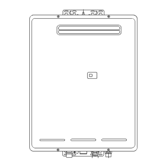
Page 12: Dimensions
4. Dimensions Cold Water Hot Water Power Infinity REU-3203W - 7 - ©Rinnai... -
Page 13: Installation
5. Installation External Wall Installation Important: Refer to the current versions of AG601/AS5601 and AS3500 for installation requirements. Infinity REU-3203W - 8 - ©Rinnai... -
Page 14: Remote Controls
6. Remote Controls Deluxe Kitchen Remote Control (MC-70) Deluxe Bathroom Remote Control (BC-70) Standard Kitchen Standard Bathroom Remote Control Remote Control (MC-33) (BC-45, BSC-45 Infinity REU-3203W - 9 - ©Rinnai... -
Page 15: Remote Controller Connection
Either colour wire can be connected to either terminal at both the Infinity or the controller. There must be at least one cable from any remote control connecting with the Infinity water heater. Connections The following diagrams show methods of connection. Infinity REU-3203W - 10 - ©Rinnai... -
Page 16: Cutaway Diagram
7. Cutaway Diagram Infinity REU-3203W - 11 - ©Rinnai... -
Page 17: Operational Flow Chart
Sparker ON Thermal fuse activated 14 flashing Overheat switch activated Fan revolves for ignition Main solenoid valve ON Solenoid valve 1 ON Modulating valve ON cont. next page cont. next page cont. next page Infinity REU-3203W - 12 - ©Rinnai... - Page 18 71 flashing Solenoid valve circuit faulty Solenoid valve 2 OFF Solenoid valve 3 OFF 10 flashing Combustion faulty Modulating valve OFF Combustion indicator OFF Combustion fan OFF (after 65 seconds) HEX outgoing temp. < 60°C Infinity REU-3203W - 13 - ©Rinnai...
-
Page 19: Operation Principles
• When water flow stops, the water flow sensor stops rotating and the pulse signal to the PCB stops. The PCB then causes the main solenoid and solenoid valves to close and the burner is extinguished. The combustion fan will continue to operate for some time to purge the combustion chamber. Infinity REU-3203W - 14 - ©Rinnai... -
Page 20: Main Components
The manifold is attached to the front of the burner module. Each bunsen burner is supplied by two injectors. • A combustion chamber. Integrated into the combustion chamber front panel are the flame rod and two ignition electrodes. Infinity REU-3203W - 15 - ©Rinnai... -
Page 21: Time Charts
11. Time Charts Normal Combustion Miss-Ignition / Flame Failure Abnormal Pre-Purge (AIr Supply/Exhaust Blockage) Infinity REU-3203W - 16 - ©Rinnai... -
Page 22: Wiring Diagram
12. Wiring Diagram COLOUR CODING : White : Black : Brown : Red : Blue : Yellow : Pink : Orange : Green : Grey Infinity REU-3203W - 17 - ©Rinnai... -
Page 23: Dip Switch Settings
Important : “Dip Switches Version 1” below applies to units with serial numbers up to and including xxxxxxx. “Dip Switches Version 2” below applies to units from serial numbers xxxxxxxx and replacement PCB’s obtained from Rinnai Australia Spare Parts. If in doubt, contact Rinnai Australia. Dip Switches explained... - Page 24 With or Without Remote Controllers Factory preset Without Remote Controllers Only Dip Switches Version 2 Gas Type Natural 1: OFF 1: ON 2: OFF 2: OFF Combustion Normal Combustion Forced ‘Low’ Combustion Forced ‘High’ Combustion Infinity REU-3203W - 19 - ©Rinnai...
- Page 25 With or Without Remote Controllers Factory preset Without Remote Controllers Only * * ° ° * * The water circuit of the REU3203W is specially modified by Rinnai to deliver hot water at 85 C and 95 C. ° ° ° °...
-
Page 26: Fault Finding
Procedures values whilst unit Detailed information operational. on how to check all (page 37) components. (page 26) Dismantling for Service Detailed information on how to remove and replace components. (page 43) Infinity REU-3203W - 21 - ©Rinnai... -
Page 27: Item
Check heat exchanger exchanger thermistor thermistor error Modulating 12, 19 Check modulating 3. e) solenoid solenoid valve valve fault. Unit stops without flame ignition. Combustion 6, 18, Check combustion fan 05 and 09 fan rotation error Infinity REU-3203W - 22 - ©Rinnai... - Page 28 3. a) - 3. d) 8 and or 9 only if controller(s) 4. Check water flow fitted. servo. 5. Check bypass servo. Anti-frost 1. Check anti-frost heater heater does components not operate. 2. Check frost sensing switch Infinity REU-3203W - 23 - ©Rinnai...
-
Page 29: Component Circuit Value Table
DC < 1 V (O) Water flow (open or closed) of 2,16 DC 4-6 V (O) Servo the servo can be determined from GY-BR the Controller dis- DC < 1 V (O) play whilst the unit is operational. Infinity REU-3203W - 24 - ©Rinnai... - Page 30 1 kohm at approx 367-450 ohm 607-699 ohm Anti Frost 625 ohm at approx Heaters 367-450 ohm 607-699 ohm 156 ohm at approx 767-883 ohm 156 ohm at approx Frost Sensing < 1 Ohm at approx Switch Infinity REU-3203W - 25 - ©Rinnai...
-
Page 31: Component And Circuit Checks
If normal, proceed to Faulty: Replace PCB. Disconnect connector ( J ) and measure resistance between both terminals of the sparker. Ω Normal: > 1M If not sparking, adjust or replace ignition plug. Faulty: Replace Sparker. Infinity REU-3203W - 26 - ©Rinnai... - Page 32 Normal: 1.8~2.2k If normal,, proceed to Faulty: Replace Solenoid Valve 2. Measure voltage between Orange and Black of Solenoid Valve connector. Normal: DC80~100V If normal, proceed to Thermal fuse Cir- cuit. Faulty: Replace PCB. Infinity REU-3203W - 27 - ©Rinnai...
- Page 33 Faulty: Replace PCB. Check the gas secondary pressure change when set temperature on the remote control changes from 37 to 55 Normal: If secondary pressure changes, go to Water Flow Servo Circuit. Faulty: Replace Modulating Valve. Infinity REU-3203W - 28 - ©Rinnai...
- Page 34 If normal, check other possible causes for flame failure (is gas valve open?, is the filter blocked? etc.). If faulty, tighten the earth lead, PCB, power cord and surge arrester. Infinity REU-3203W - 29 - ©Rinnai...
- Page 35 Measure voltage between Yellow - Black of relay connector (E Normal: DC 4~7V If normal, proceed to 2. Faulty: Replace water flow sensor. Note: For controller readout of water flow whilst operational refer maintenance monitor (chapter 17) No. 1. Infinity REU-3203W - 30 - ©Rinnai...
- Page 36 Short circuit: Resistance < 1 If normal, proceed to Water Flow Servo Circuit If faulty, replace Heat Exchanger Outlet Thermistor. Note: For controller readout of thermistor teperature whilst operational refer maintenance monitor (chapter 17) No. 11. Infinity REU-3203W - 31 - ©Rinnai...
- Page 37 Check whether or not the fuse (3A) x 2 has blown by measuring the resistance. Normal: <1Ω If normal go to step Electrical Fuse 13. Faulty: Replace fuse/s (3Ax2). Check for a short next time it’s turned off. Infinity REU-3203W - 32 - ©Rinnai...
- Page 38 Green of connector (D) on PCB. Normal: AC 12~18V If normal, proceed to 4. Faulty: Replace transformer. Note) The above transformer voltages are measured while the appliance is in standby mode - not while it is operating. Infinity REU-3203W - 33 - ©Rinnai...
- Page 39 Faulty: Because normal voltage is not given due a short circuit, despite the PCB being in normal state, check Water Flow Servo circuit. If solution is not given from the above replace PCB. Infinity REU-3203W - 34 - ©Rinnai...
- Page 40 Disconnect relay connector ( J ) and ( J and measure resistance between Yellow and Yellow on each conector on heater side. Ω Normal: 653 If normal, proceed to c. Faulty: Replace Anti-frost Heater B (assy). Infinity REU-3203W - 35 - ©Rinnai...
- Page 41 18.Frost Sensing Switch. Disconnect relay connector ( J ) and measure resistance between Blue and Blue. Ω Normal: < 1 If normal, check wiring (AC240V cir- cuit). Faulty: Replace Frost Sensing Switch. Infinity REU-3203W - 36 - ©Rinnai...
-
Page 42: Maintenance Monitor / Error History
*Note 1 Fan Frequency rpm Conversion (rpm) = (Hz) x15 Remote control connection none 0 or 1 *Note 2 *Note 2 Remote Control Connections Bathroom Remote Controls connected Display “0” Additional remote Kitchen remote “1” “0 1” Infinity REU-3203W - 37 - ©Rinnai... - Page 43 Clock display. To return to normal operation. • Press the ON/OFF button again while holding the Water Temperature “UP” (Hotter) button. • This feature will automatically shut down after 3 minuets. Infinity REU-3203W - 38 - ©Rinnai...
-
Page 44: Gas Pressure Setting Procedure
Set the Infinity to 'Forced Low' combustion by setting No. 2 dipswitch of the bottom (SW2) set of dip switches to 'ON'. (fig 3) 10) Check the burner test point pressure. Infinity REU-3203W - 39 - ©Rinnai... - Page 45 22) Replace the front cover of the appliance. Warning DURING PRESSURE TESTING OF THE INSTALATION ENSURE GAS COCK SITUATED BEFORE UNIT IS SHUT OFF. fAILURE TO DO SO MAY RESULT IN SERIOUS DAMAGE TO THE APPLIANCE AND POSSIBLE INJURY. Infinity REU-3203W - 40 - ©Rinnai...
-
Page 46: Gas Conversion Procedure
Remove manifold (complete assembly). (7 screws) Replace the manifold (complete assembly) and the packing. (7 screws) Note: Do not lose or damage the O-ring whe reassembling. Ensure connections for the solenoid and sparker lead are made properly. Infinity REU-3203W - 41 - ©Rinnai... - Page 47 Change over the gas conversion switches (1 ~ 4) on the PCB unit Reset Gas pressurs as per instructions in 18. Gas Pressure Setting Procedure. (page 39) Infinity REU-3203W - 42 - ©Rinnai...
-
Page 48: Dismantling For Service
11. Removal of the Thermal Fuse and OHS ....... 47 Unless otherwise stated, re-assembly is the reverse of dismantling. Infinity REU-3203W - 43 -... -
Page 49: Removal Of The Front Panel
Ensure O-rings are not lost or damamged.. 2) Removal of the PCB Unit a. Remove the front panel. (Refer Item 1.) b. Remove two (2) PCB unit fixing screws and pull out forward. Infinity REU-3203W - 44 - ©Rinnai... -
Page 50: Removal Of The Sparkers
Remove PCB unit (assembly). (Refer Item 2.) b. Remove three (3) combustion fan screws, pull c. Remove two (2) transformer screws and pull out forward and slide to the side to remove fan. forward (2 screws). Infinity REU-3203W - 45 - ©Rinnai... -
Page 51: Removal Of The Gas Inlet, Solenoids And Flame Rod
Remove damper (3 screws). d. Remove one (1) gas control (assy) screw and pull out gas control (assy). f. Remove two (2) burner retaining screws, then remove combustion chamber front panel (9 screws). Infinity REU-3203W - 46 - ©Rinnai... -
Page 52: Removal Of The Heat Exchanger
Remove four (4) heat exchanger unit screws. b. Take out the heat exchanger unit. Refer to 10). c. Remove the thermal fuse. Note: After replacing, install the thermal fuse as in the following diagrams. Heat Exchanger RHS Heat Exchanger Front Infinity REU-3203W - 47 - ©Rinnai... - Page 53 Heat Exchanger Back d. Remove one (1) screw of the bi-metal overheat switch. Infinity REU-3203W - 48 - ©Rinnai...
-
Page 54: Exploded Diagram
21. Exploded Diagram Infinity REU-3203W - 49 - ©Rinnai... - Page 55 Infinity REU-3203W - 50 - ©Rinnai...
- Page 56 Infinity REU-3203W - 51 - ©Rinnai...
- Page 57 Infinity REU-3203W - 52 - ©Rinnai...
-
Page 58: Parts List
92086966 3437 PLATE, Restriction CASE Lower, Burner CASE Front, Burner PACKING 3439 BURNER 3440 PANEL, Burner Case Back PANEL Comp. Assy., Comb. Chamber Fr. Panel PANEL Assy. Comb.,Chamber Fr. Panel GASKET, Combustion Chamber 3443 Infinity REU-3203W - 53 - ©Rinnai... - Page 59 92081843 3492 HARNESS - Wire, Fan Motor 3493 HARNESS - Wire, Sensor 3495 HARNESS - Wire, Water Flow Servo 92081850 3505 HARNESS - Wire, Transformer 92081868 3506 HARNESS - Wire, 3 Amp Fuse 3391 Infinity REU-3203W - 54 - ©Rinnai...
- Page 60 3882 SWITCH, Frost Sensing 2362 HEATER , Anti Frost Valve 230V (K only) 3544 TRANSFORMER - Large 3550 CONTROL KIT, Kitchen Remote Control CONTROL KIT, Bathroom Remote Control CONTROL KIT, 2nd Bathroom Remote Control Infinity REU-3203W - 55 - ©Rinnai...
- Page 61 Notes Infinity REU-3203W ©Rinnai...
- Page 62 Infinity REU-3203W ©Rinnai...
- Page 63 Infinity REU-3203W ©Rinnai...
-
Page 64: Service Contact Points
NEW ZEALAND LTD. Internet: www.rinnai.co.nz E-mail: sales@rinnai.co.nz Head Office, New Zealand 691 Mt. Albert Road, Royal Oak, Auckland P O Box 24-068 Tel: (09) 625 4285 Fax: (09) 624 3018 24 hr Service Tel: 0800 746624 (0800 Rinnai) REU-3203W SM 01/2002...
Need help?
Do you have a question about the INFINITY REU-3203W and is the answer not in the manual?
Questions and answers