Table of Contents
Advertisement
Quick Links
Advertisement
Table of Contents

Subscribe to Our Youtube Channel
Related Manuals for Bard SH611D


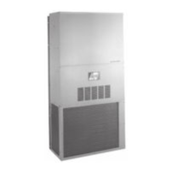
Summary of Contents for Bard SH611D
- Page 1 INSTALLATION INSTRUCTIONS WALL MOUNTED PACKAGE HEAT PUMPS Model SH611D Manual : 2100-414C Bard Manufacturing Company Supersedes: 2100-414B Bryan, Ohio 43506 File: Volume III Tab 17 Since 1914...Moving ahead just as planned. Date: 05-06-05 © Copyright 2004...
-
Page 2: Table Of Contents
CONTENTS Start Up Getting Other Information and Publications For More Information ..........1 Important Installer Note ........16 Crankcase Heaters ..........16 Wall Mount General High Pressure Switch ......... 16 Heat Pump Wall Mount Model Nomenclature ..2 Three Phase Scroll Compressor Start Up ... 16 Shipping Damage .......... -
Page 3: Getting Other Information And Publications
Getting Other Information and Publications FOR MORE INFORMATION, CONTACT These publications can help you install the air THESE PUBLISHERS: conditioner or heat pump. You can usually find these at your local library or purchase them directly from the publisher. Be sure to consult current edition of each ACCA Air Conditioning Contractors of America standard. -
Page 4: Wall Mount General
WALL MOUNT GENERAL INFORMATION HEAT PUMP WALL MOUNT MODEL NOMENCLATURE CONTROL MODULES MODEL NUMBER REVISIONS 00 – 0 KW 09 – 9 KW COIL OPTIONS CAPACITY X - Standard 10 – 10 KW 61 - 5 Ton 1 - Phenolic Coated Evaporator VOLTS &... -
Page 5: Figure 1 Unit Dimensions
Manual 2100-414C Page... -
Page 6: Shipping Damage
TABLE 2 ELECTRICAL SPECIFICATIONS & - - - - - - - - - - - - - - - - - - - - - - - - - - - - - - - - - - - - - - - - - - - - -... -
Page 7: Filters
Any grille that meets with 5/8 inch louver criteria may be used. It is recommended that Bard Return Air Grille Kit RG2 through RG5 or RFG2 through RFG5 be installed when no return duct is used. Contact... -
Page 8: Installation Instructions
INSTALLATION INSTRUCTIONS WALL MOUNTING INFORMATION WARNING 1. Two holes for the supply and return air openings must be cut through the wall as shown in Figure 3. 2. On wood frame walls, the wall construction must be Failure to provide the 1/4 inch clearance strong and rigid enough to carry the weight of the between the supply duct and a combustible unit without transmitting any unit vibration. -
Page 9: Figure 3 Mounting Instructions
Manual 2100-414C Page... -
Page 10: Figure 4 Electric Heat Clearance
FIGURE 4 ELECTRIC HEAT CLEARANCE SIDE SECTION VIEW OF SUPPLY AIR DUCT FOR WALL MOUNTED UNIT SHOWING 1/4 INCH CLEARANCE TO COMBUSTIBLE SURFACES. MIS-277 WARNING A minimum of 1/4 inch clearance must be maintained between the supply air duct and combustible materials. This is required for the first 3 feet of ducting. -
Page 11: Figure 5 Wall Mounting Instructions
FIGURE 5 WALL MOUNTING INSTRUCTIONS SEE FIGURE 4 – MOUNTING INSTRUCTIONS MIS-548 FIGURE 6 WALL MOUNTING INSTRUCTIONS SEE UNIT DIMENSIONS, FIGURE 1, FOR ACTUAL DIMENSIONS Manual 2100-414C Page... -
Page 12: Figure 7 Common Wall Mounting Installations
FIGURE 7 COMMON WALL MOUNTING INSTALLATIONS FREE AIR FLOW NO DUCT DUCTED SUPPLY RETURN AT UNIT FALSE WALL INSTALLATION CLOSET INSTALLATION MIS-550 Manual 2100-414C Page... -
Page 13: Wiring - Main Power
The assured by Bard to work with this equipment. correct size must be used for proper circuit protection and also to assure that there will be no... -
Page 14: Figure 8 Wiring With Cs2000A Monitor
FIGURE 8 SHXXXDX – HOT GAS REHEAT DURING DEHUMIDIFICATION WITH CS2000A ENERGY MONITOR FULL TIME DEHUMIDIFICATION IMPORTANT NOTE: Only the thermostat and subbase combinations as shown above and in Table 4 will work with this equipment. The thermostat and subbase must be matched and the correct operation can be assured only by proper selection and application of these parts. - Page 15 FIGURE 9 SHXXXDX – HOT GAS REHEAT DURING DEHUMIDIFICATION WITH PROGRAMMABLE THERMOSTAT FULL TIME DEHUMIDIFICATION IMPORTANT NOTE: Only the thermostat and subbase combinations as shown in Table 4 will work with this equipment. The thermostat and subbase must be matched, and the correct operation can be assured only be proper selection and application of these parts.
-
Page 16: Compressor Cutoff Thermostat And Outdoor Thermostats
FIGURE 10 10KW 1 PH – 6 & 9 KW 3 PH MIS-409 COMPRESSOR CUT OFF THERMOSTAT COMPRESSOR MALFUNCTION LIGHT AND OUTDOOR THERMOSTATS Actuation of the flashing red LED is accomplished by a Heat pump compressor operation at outdoor relay output from the heat pump control board which is temperatures below 0°... -
Page 17: Low Voltage Connections
LOW VOLTAGE CONNECTIONS NOTE: For total and proper control using DDC, a total of 7 controlled outputs are required (6 if These units use a grounded 24 volt AC low voltage no ventilation system is installed). For proper circuit. system operation under Emergency Heat conditions where the compressor needs to be The “R”... -
Page 18: Figure 11 Start Up Procedure Decal
START UP IMPORTANT INSTALLER NOTE FIGURE 11 START UP LABEL For improved start up performance wash the indoor coil with a dish washing detergent. IMPORTANT CRANKCASE HEATERS These procedures must be followed SH611-B and -C are provided with compressor at initial start up and at any time power crankcase heat. -
Page 19: Phase Monitor
HEATING SEQUENCE – On a call for heating, the PHASE MONITOR compressor and reversing valve of the unit are energized All units with three phase compressors are equipped to provide heat pump heating. If the room temperature with a 3 phase line monitor to prevent compressor falls below the 2nd stage heating set point backup damage due to phase reversal. -
Page 20: Figure 12 Defrost Control Board
DEFROST CYCLE There is a cycle speed up jumper on the control. This can be used to reduce the time between defrost cycle The defrost cycle is controlled by temperature and time operation without waiting for time to elapse. on the solid state heat pump control. See Figure 12. Use a small screwdriver or other metallic object, or When the outdoor temperature is in the lower 40°... -
Page 21: Troubleshooting
TROUBLESHOOTING SOLID STATE HEAT PUMP CONTROL 3. Turn thermostat blower switch to auto position. TROUBLESHOOTING PROCEDURE Indoor blower should stop. 1. Turn on AC power supply to indoor and outdoor 4. Set system switch to heat or cool. Adjust thermostat units. -
Page 22: Checking Temperature Sensor Outside Unit Circuit
CHECKING TEMPERATURE SENSOR 3. Check resistance reading to chart of resistance use OUTSIDE UNIT CIRCUIT sensor ambient temperature. (Tolerance of part is ± 10%) 1. Disconnect temperature sensor from board and from outdoor coil. 4. If sensor resistance reads very low, then sensor is shorted and will not allow proper operation of the 2. -
Page 23: Figure 13 Fan Blade Setting
Subtract .08 static for 2" filter 3. Remove screws holding fan shroud to condenser and bottom. Nine (9) screws. NOTE: SH611D is shipped with the indoor 4. Unwire condenser fan motor. blower on high speed for ducted 5. Slide complete motor, fan blade, and shroud applications. -
Page 24: Pressure Tables
TABLE 11 PRESSURE TABLE COOLING Air Temperature Entering Outdoor Coil °F Low side pressure ± 2 PSIG High side pressure ± 5 PSIG Tables are based upon rated CFM (airflow) across the evaporator coil. If there is any doubt as to correct operating charge being in the system, the charge should be removed, system evacuated and recharged to serial plate instruction. -
Page 25: Cooling Mode
FIGURE 14 BARD HEAT PUMP COOLING MODE CIRCUIT DIAGRAM FIGURE 15 BARD HEAT PUMP DEHUMIDIFICATION MODE CIRCUIT DIAGRAM Manual 2100-414C Page...
Need help?
Do you have a question about the SH611D and is the answer not in the manual?
Questions and answers