Table of Contents
Advertisement
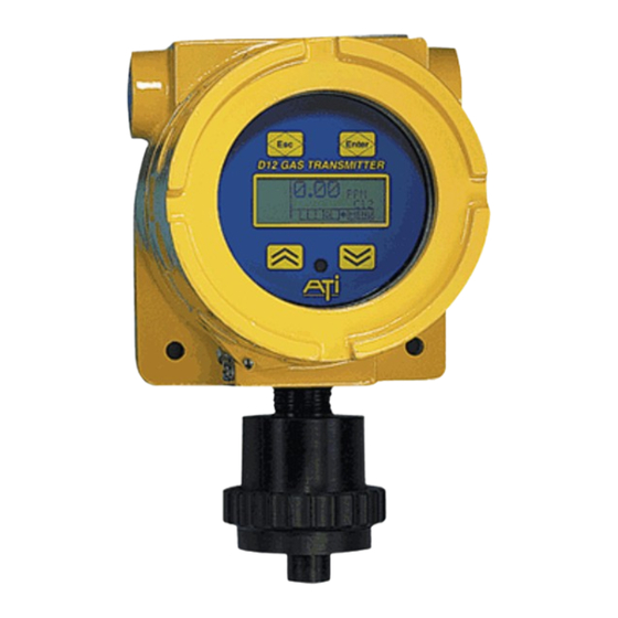
Series D12
Toxic Gas Transmitter
Home Office
Analytical Technology, Inc.
6 Iron Bridge Drive
Collegeville, PA 19426
Ph: 800-959-0299
610-917-0991
Fax: 610-917-0992
Email: sales@analyticaltechnology.com
With H10 Smart Sensor
European Office
ATI (UK) Limited
Unit 1 & 2 Gatehead Business Park
Delph New Rd. Delph
Saddleworth OL3 5DE
Ph: +44 (0)1457-873-318
Fax: + 44 (0)1457-874-468
Email: sales@atiuk.com
Advertisement
Table of Contents

Related Manuals for ATI Technologies d12 series


Summary of Contents for ATI Technologies d12 series
- Page 1 Series D12 Toxic Gas Transmitter With H10 Smart Sensor Home Office European Office Analytical Technology, Inc. ATI (UK) Limited 6 Iron Bridge Drive Unit 1 & 2 Gatehead Business Park Collegeville, PA 19426 Delph New Rd. Delph Saddleworth OL3 5DE Ph: 800-959-0299 Ph: +44 (0)1457-873-318 610-917-0991...
-
Page 2: Product Warranty
Series D12 Toxic Gas Transmitter with H10 Smart Sensor Product Warranty Analytical Technology, Inc. (Manufacturer) warrants to the Customer that if any part(s) of the Manufacturer's products prove to be defective in materials or workmanship within the earlier of 18 months after the date of shipment or 12 months after the date of start-up, such defective parts will be repaired or replaced free of charge. -
Page 3: Table Of Contents
Series D12 Toxic Gas Transmitter with H10 Smart Sensor Table Of Contents Span Calibration ............... 38 INTRODUCTION ______________________ 5 Calibration Terminology ............ 38 Calibration Kits ..............38 COMPONENTS ............5 Indications During Sensor Calibration ....... 38 Calibration Exceptions ............38 D12 Toxic Transmitter ............. 5 Zero Calibration Procedure .......... - Page 4 Series D12 Toxic Gas Transmitter with H10 Smart Sensor Restart ................72 Communication Setup Page ..........76 Resets ................72 Flow Control ..............76 Report Format ..............77 SPARE PARTS _______________________ 73 Report Control ..............77 APPENDIX A. ________________________ 76 ....
-
Page 5: Introduction
Series D12 Toxic Gas Transmitter with H10 Smart Sensor INTRODUCTION COMPONENTS D12 Toxic Transmitter The D12 Toxic Transmitter is used to monitor for gas leaks near storage cylinders, process piping, or gas feed equipment in virtually any type of industrial plant environment. The transmitter housing is explosion proof, and is rated for use in hazardous locations (see specifications). - Page 6 Series D12 Toxic Gas Transmitter with H10 Smart Sensor Table 1. H10 Smart Sensors Part No. Standard Minimum Maximum Range Range Range GENERAL GASES Acetylene 00-1057 0-200 PPM 0-50 PPM 0-500 PPM Alcohol 00-1043 0-200 PPM 0-50 PPM 0-500 PPM Alcohol 00-1044 0-500 PPM...
- Page 7 Series D12 Toxic Gas Transmitter with H10 Smart Sensor ACID GASES Hydrogen Bromide 00-1455* 0-20 PPM 0-10 PPM 0-200 PPM Hydrogen Chloride 00-1017* 0-10 PPM 0-10 PPM 0-200 PPM Hydrogen Cyanide 00-1018* 0-10 PPM 0-10 PPM 0-200 PPM Hydrogen Fluoride 00-1019* 0-10 PPM 0-10 PPM...
-
Page 8: Specifications
Series D12 Toxic Gas Transmitter with H10 Smart Sensor SPECIFICATIONS Table 2. Specifications Sensor Type Electrochemical cell Gas Type Select from list (see Table 1) Range User adjustable within limits of selected sensor (see Table 1) Response Time Sensor dependent Accuracy Generally ±10% of value, but limited by available calibration gas accuracy. -
Page 9: Installation
Series D12 Toxic Gas Transmitter with H10 Smart Sensor INSTALLATION MECHANICAL MOUNTING Transmitter Figure 2 shows the dimensions of the HAZARDOUS LOCATIONS transmitter enclosure and the location and size of Connect housing to earth ground. Use explosion proof conduit, and seal it inside and out. the electrical conduit Follow national, state, and local, electrical codes. -
Page 10: H10 Sensor Duct-Mount Option
Series D12 Toxic Gas Transmitter with H10 Smart Sensor H10 Sensor Duct-Mount Option The H10 sensor duct mount option allows H10 Smart Sensors to be installed in a duct or pipe, and provides easy access to the sensor for service. The assembly is comprised of a special H10 sensor holder (Figure 3) that slides into the hollow duct mount adapter (Figure 4). -
Page 11: Figure 5. Duct-Mount Adapter
Series D12 Toxic Gas Transmitter with H10 Smart Sensor Figure 5. Duct-mount adapter Figure 6. Duct-mount assembly Revision N (7/15) -
Page 12: Electrical Connections
Series D12 Toxic Gas Transmitter with H10 Smart Sensor ELECTRICAL CONNECTIONS Board Stack The transmitter consists of four circuit boards, known collectively as the “stack”. From top to bottom, they are the, Display, CPU, Isolation, and Power Supply boards. The top three boards, Display, CPU, and Isolation, are fastened together with metal standoffs, and plug into the Power Supply board, which is fastened to the lower housing with similar metal standoffs. -
Page 13: Power Supply Board Connections
Series D12 Toxic Gas Transmitter with H10 Smart Sensor Power Supply Board Connections Electrical connections are made to terminal blocks on the Power Supply board. Power, current loop, (optional) digital communications, and remote alarm reset, are connected at TB1. Connections to the three (optional) relays are made at TB2. -
Page 14: External Connections
Series D12 Toxic Gas Transmitter with H10 Smart Sensor External Connections ATI A17/B14 Monitor(s), 2-Wire Mode D12 (toxic gas) transmitters may be connected in 2-wire mode to an ATI A17/B14 receiver system. In 2-wire mode, transmitters will not include alarm relays, LCD backlighting, or RS232/RS485 communication options. -
Page 15: Ati A17/B14 Monitor(S), 3-Wire Mode
Series D12 Toxic Gas Transmitter with H10 Smart Sensor ATI A17/B14 Monitor(s), 3-Wire Mode D12 transmitters may be connected in 3-wire mode to an ATI A17/B14 receiver system. In 3-wire mode, transmitters will include alarm relays, LCD backlighting, and RS232/RS485 communication options. -
Page 16: Power Only, No Output Options
Series D12 Toxic Gas Transmitter with H10 Smart Sensor Power Only, No Output Options If there are no output options, transmitters may be powered from a single, primary supply as shown. Size each power supply according to the number of transmitters, the current demand of each (see specifications), and the wire resistance. -
Page 17: Current Loop Receiver, Single Supply (2-Wire Mode)
Series D12 Toxic Gas Transmitter with H10 Smart Sensor Current Loop Receiver, Single Supply (2-Wire Mode) The transmitter will source current to a loop receiver in 2-wire mode, as shown. A single power supply provides loop power, which is sufficient to power the transmitter, but without relays, LCD backlighting, and RS232/RS485 communications. -
Page 18: Current Loop Receiver, Single Supply (3-Wire Mode)
Series D12 Toxic Gas Transmitter with H10 Smart Sensor Current Loop Receiver, Single Supply (3-Wire Mode) The transmitter will source current to a loop receiver as shown. A single power supply provides both primary and loop power to the transmitter. Size each power supply according to the number of transmitters, the current demand of each (see specifications), and the wire resistance. -
Page 19: Current Loop Receiver, Dual Supplies (4-Wire Mode)
Series D12 Toxic Gas Transmitter with H10 Smart Sensor Current Loop Receiver, Dual Supplies (4-Wire Mode) To reduce the power requirement of a single current loop supply, the transmitter may be powered from both a primary and loop supply, providing the following conditions are met. 1. -
Page 20: Hart Transmitter, Point-To-Point (2-Wire)
Series D12 Toxic Gas Transmitter with H10 Smart Sensor HART Transmitter, Point-to-Point (2-Wire) The HART “Point-to-Point” connection permits the transmitter to communicate digitally, while retaining the functionality of its 4-20mA current loop. Setting the transmitter’s polling address to 0 permits the current loop to function normally. According to HART specifications, the current loop must be terminated with a load resistor between 230 and 1100 ohms;... -
Page 21: Hart Transmitter, Point-To-Point, Active Source (3-Wire)
Series D12 Toxic Gas Transmitter with H10 Smart Sensor HART Transmitter, Point-to-Point, Active Source (3-Wire) The HART “Point-to-Point” connection permits the transmitter to communicate digitally, while retaining the functionality of its 4-20mA current loop. Setting the transmitter’s polling address to 0 permits the current loop to function normally. -
Page 22: Figure 17. Hart Transmitter Operation, Multi-Drop
Series D12 Toxic Gas Transmitter with H10 Smart Sensor The HART multi-drop connection permits up to 15 transmitters to communicate digitally on the same bus, but at the cost of analog current signaling. Setting the transmitter’s polling address from 1 to 15 fixes the current loop output at 4mA. -
Page 23: Modbus Rs485 Multi-Drop
Series D12 Toxic Gas Transmitter with H10 Smart Sensor Modbus RS485 Multi-drop RS485 operation requires the transmitter to be wired in 3- or 4- wire mode. Modbus permits up to 247 devices to communicate digitally on the same bus; however, RS485 limits this to 32. Request the D12 Transmitter Modbus Interface Manual for complete details on the Modbus interface. -
Page 24: Computer Rs232
Series D12 Toxic Gas Transmitter with H10 Smart Sensor Computer RS232 RS232 operation requires the transmitter to be wired in 3- or 4- wire mode. See Printing Data Log Reports in Appendix A.for details on sending the data log to a printer or computer. Request D12 Transmitter Modbus Interface Manual for complete details on the Modbus interface. -
Page 25: Remote Sensor Wiring
Series D12 Toxic Gas Transmitter with H10 Smart Sensor Remote Sensor Wiring The figure below shows the wiring of the remote sensor option, which allows separation of the transmitter and sensor by up to 50 feet. Interconnect cable is sold separately. Connections are made to terminal blocks in the transmitter and J-box (junction box) assembly. -
Page 26: Duct-Mount Sensor Wiring
Series D12 Toxic Gas Transmitter with H10 Smart Sensor Duct-Mount Sensor Wiring The figure below shows the wiring of the sensor duct-mount option, which allows the sensor to be installed inside of a duct or pipe. The cable plugs into the rear of the sensor holder, and connects to a terminal block in the transmitter. -
Page 27: Heater Option For Sensor/Generator Housing
Series D12 Toxic Gas Transmitter with H10 Smart Sensor Heater Option for Sensor/Generator Housing The heater should be supplied with 24VDC to provide approximately 5.8W to the housing. This may be derived from the transmitter supply in 3-wire mode, as shown below, or from a separate power supply. -
Page 28: Cpu Board Configuration
Series D12 Toxic Gas Transmitter with H10 Smart Sensor CPU Board Configuration Install one jumper plug on Pin 1 Jumper block on JP4 JP4 as prescribed by Note (see table above) communication interface. I M P O R T A N T location of pin 1 After re-installing the transmitter board stack, set... -
Page 29: Operation
Series D12 Toxic Gas Transmitter with H10 Smart Sensor OPERATION OPERATOR INTERFACE Interface Panel The D12 operator interface is non-intrusive, so you do not have to remove the housing cover to view the display, configure the transmitter, or calibrate the sensor. It features a backlighted*, 96x32 dot LCD display, and four “keys”. -
Page 30: Startup Review Sequence
Series D12 Toxic Gas Transmitter with H10 Smart Sensor Startup Review Sequence When the transmitter starts, the display cycles through a series of pages to review the configuration of the transmitter, sensor, and generator. Alarms are inhibited, and the output of the transmitter is held at 4.0 mA (17.4mA for Oxygen sensors). -
Page 31: Main Display Page
Series D12 Toxic Gas Transmitter with H10 Smart Sensor Main Display Page The Main Display Page shows the name and concentration of the target gas, and units of measurement (PPM, PPB, %, etc). Indicators on the left and below show alarm and operating status. Indicates concentration Main Reading High Alarm Active Flag... -
Page 32: Main Reading
Series D12 Toxic Gas Transmitter with H10 Smart Sensor Main Reading The main reading represents the gas concentration value and appears on the Main Display, along with the gas name, and units of concentration. It is reported on the 4-20mA output , and is the PV (Primary Variable) reported on the optional HART™... -
Page 33: Variable Editing
Series D12 Toxic Gas Transmitter with H10 Smart Sensor Variable Editing When a variable is selected, the edit cursor appears. The shape of the cursor symbolizes the up-down scroll nature of the value being edited. To provide feedback about which key is being activated, the cursor changes to a solid up-arrow when the magnet is touching the Up key, and to a solid down-arrow when the magnet is touching the Down key. -
Page 34: Sensors And Generators
Series D12 Toxic Gas Transmitter with H10 Smart Sensor SENSORS and GENERATORS Sensor Setup As mentioned, the D12 transmitter accepts a wide variety of H10 Smart Sensors, which configure the transmitter with the name of the gas, the full-scale range, units of concentration, blanking, damping, alarm settings, and data to assist the transmitter with transforming the sensor’s output signal into a representation of gas concentration. -
Page 35: Sensor More Page
Series D12 Toxic Gas Transmitter with H10 Smart Sensor Sensor More Page >Menu >Setup >Sensor >More ►Cal_History Test_History Temp= 21.7°C Figure 31. Sensor “more” page Table 5. Sensor “more” variables Variables Description Cal_History Cal_History is a link to the Calibration History page (see Sensor Calibration Records). -
Page 36: Removing Generators
Series D12 Toxic Gas Transmitter with H10 Smart Sensor operator to verify the new sensor, full-scale range, and alarm settings . The startup review is illustrated in Figure 25. Warning: Changing sensor types will clear the data log. If data logging is turned on (indicated by the “D” status indicator appearing on the Main Display), and the sensor is replaced by one with a different part number, you will be prompted to clear the data log during review. -
Page 37: Bump-Testing
Series D12 Toxic Gas Transmitter with H10 Smart Sensor Bump-Testing “Bump-testing” refers to a test whereby the sensor is briefly exposed to gas in order to verify the reading moves upscale from zero. It is recommended that it be performed at least once a month, using a small amount of bottled span gas. -
Page 38: Calibration
Series D12 Toxic Gas Transmitter with H10 Smart Sensor Calibration Calibration Frequency While the transmitter itself requires no periodic calibration, H10 sensors should be “zero” and “span” calibrated every 3-6 months, based upon environmental factors. Sensors frequently exposed to dirt, oil mist, vapors, or very dry air, may require more frequent calibration. -
Page 39: Zero Calibration Procedure
Series D12 Toxic Gas Transmitter with H10 Smart Sensor Zero Calibration Procedure Performing a zero calibration requires a bottled “Zero-gas” with a 500 cc/min regulator, calibration D12 GAS TRANSMITTER adapter, and a convenient length of ¼” tubing. The gas used depends on the type of sensor installed. For example, an H S sensor may be zeroed with Zero-air, while Oxygen sensors must be zeroed with Nitrogen. -
Page 40: Span Calibration Procedure
Series D12 Toxic Gas Transmitter with H10 Smart Sensor Span Calibration Procedure Span calibration* requires a bottled “span-gas” with a 500 cc/min regulator, calibration adapter, and a D12 GAS TRANSMITTER convenient length of ¼” tubing. The gas type and concentration used depends on the type of sensor installed. -
Page 41: Calibration Of Duct-Mount H10 Sensors
Series D12 Toxic Gas Transmitter with H10 Smart Sensor Calibration of Duct-Mount H10 Sensors To Zero and Span calibrate a duct-mounted H10 sensor; pull the sensor out of the duct until the calibration locking pin clicks into the retaining slot. By pulling back slowly, the retaining pin will drop into place and automatically locate the sensor just behind the gas inlet port. -
Page 42: Sensor Calibration Records
Series D12 Toxic Gas Transmitter with H10 Smart Sensor Sensor Calibration Records A calibration record is written into the sensor memory each time a zero or span calibration is performed, and when a calibration Undo is performed. Enough memory is reserved for 63 zero calibrations and 63 span calibrations. -
Page 43: Auto-Test
Series D12 Toxic Gas Transmitter with H10 Smart Sensor Auto-test The Auto-test option verifies the serviceability of the transmitter on a prescribed schedule by exposing the sensor to a small amount of gas, and verifying a minimum response. Three attempts per test are made, and if the sensor does not respond on the third attempt, a fault alarm is triggered (may be optionally disabled). -
Page 44: Revision N (7/15
Series D12 Toxic Gas Transmitter with H10 Smart Sensor Table 6. Compatible generators and sensors C18 Generator Generator Compatible H10 Sensors Part No. Type Sensor Type Part No. Min. Range Max. Range 00-1239 00-1000 1 PPM 5 PPM 00-1001 5 PPM 20 PPM 00-1002 1 PPM... -
Page 45: Auto-Test Controls
Series D12 Toxic Gas Transmitter with H10 Smart Sensor Auto-test Controls Auto-test is controlled by the Status variable, which appears on the Auto-test page shown below. >Menu >Setup >Auto-T ►Status=OFF Setup NextAT GasGen Figure 40. Auto-test control page History Table 7. Auto-test control variables Variables Description Status... -
Page 46: Auto-Test Setup Options
Series D12 Toxic Gas Transmitter with H10 Smart Sensor Auto-test Setup Options The Auto-test Setup Options page variables control the behavior of the >Menu>Setup>Auto-T>NextAT transmitter during Auto-test. ►Log_Data=YES Cause_Fault=YES Override_mA=YES Variables Description Log_Data The Log_Data variable controls values logged during Auto-test. When set to YES (default), the gas concentration (main reading) is logged as usual, including any increase caused by the gas generator. -
Page 47: Auto-Test History
Series D12 Toxic Gas Transmitter with H10 Smart Sensor Auto-test History The Auto-test History page provides a summary of passes, failures, and >Menu>Setup>Auto-T>History retries, which are maintained in the sensor memory. Since three Passes= attempts are made, there are always two retries before a failure is Failures= recorded. -
Page 48: Figure 42. Auto-Test Sequence
Series D12 Toxic Gas Transmitter with H10 Smart Sensor Main Display MENU Auto-Test Page Retry every minute for AUTO TEST 1 hour and 30 minutes. ►Start 00:00 Reading= 0.0PPM Message Page Main Display Gas Conc PLEASE NOTE Concentration … Greater Than 10% Range? I L A D MENU... -
Page 49: Alarms And Relays
Series D12 Toxic Gas Transmitter with H10 Smart Sensor ALARMS and RELAYS Three gas concentration alarms and one fault alarm are standard in the D12 transmitter. Alarm status flags appear on the Main Display, and status is available over the optional serial interface. Alarms may be assigned to activate one or more of three optional relays (see Alarm Relays). -
Page 50: Gas Alarm Operation
Series D12 Toxic Gas Transmitter with H10 Smart Sensor Gas Alarm Operation Figure 46 depicts relationships between variables associated with a rising gas alarm, and how they function in the presence of a gas leak, and recovery. Set_Point Res_Point Set_Delay Res_Delay S e c o n d s Conc. -
Page 51: Gas Alarm Setup
Series D12 Toxic Gas Transmitter with H10 Smart Sensor Gas Alarm Setup Variables for the gas alarms are configured on the respective setup pages, as shown in Figure 48, and described in Table 9. ►Alarm Relays Warning Setup Caution Test Inhibit >Caution >Alarm... - Page 52 Series D12 Toxic Gas Transmitter with H10 Smart Sensor Active=ABOVE_SP Upper limit = current set point value Lower limit = lowest set point value Active=BELOW_SP Upper limit = highest set point value Lower limit = current set point value When the set point is reprogrammed, the reset point value is reprogrammed to the same value.
-
Page 53: Fault Alarms
Series D12 Toxic Gas Transmitter with H10 Smart Sensor Fault Alarms When a fault alarm occurs, the Main Display appears as shown below. By default, new alarms are inhibited, and active alarms are held so that relays controlling lights, sirens, and fans may continue to operate (this behavior may be modified on the Alarms Setup pages). -
Page 54: Revision N (7/15
Series D12 Toxic Gas Transmitter with H10 Smart Sensor SPI Bus Error Serial peripheral interface bus has faulted. 1. Cycle power off and on 2. Replace upper stack 3. Replace full stack ADC1 Read Error The analog-to-digital converter channel 1. Cycle power off and on assigned to the sensor’s temperature output 2. -
Page 55: Revision N (7/15
Series D12 Toxic Gas Transmitter with H10 Smart Sensor Autotest Failed Auto-test failed after 3 attempts. 1. Replace generator 2. Replace sensor 3. Replace upper stack 4. Replace full stack Use 3-Wire Power Relay option jumper is installed, but 1. If relays are not used, remove transmitter is powered from loop (2-wire). -
Page 56: Alarm Relays
Series D12 Toxic Gas Transmitter with H10 Smart Sensor Alarm Relays The D12 transmitter provides three optional SPDT mechanical relays rated for 5 amps, non-inductive loads at 250VAC. These relays are suitable for switching small loads, such as horns and warning lights, but should not be used to switch motors or other high current, inductive loads. -
Page 57: Relays Setup
Series D12 Toxic Gas Transmitter with H10 Smart Sensor Relays Setup Relays are configured in the Relays Setup page, which is accessed by selecting Menu, Setup, Alarms, and (Relays) Setup. Select the alarm trigger source (Alarm,Warning,Caution,Fault), and failsafe property (Normal-On or Normal-Off). >Menu >Setup >Alarms Alarm Relays... -
Page 58: Inhibiting Alarms
Series D12 Toxic Gas Transmitter with H10 Smart Sensor Inhibiting Alarms Alarms should be inhibited to prevent false activation, such as done just prior to “bump-testing” the sensor. The most convenient method for temporarily inhibiting alarms is from the Main Display. Hold the magnet over the ESC key for 2 seconds, and remove it. -
Page 59: M A Output
Series D12 Toxic Gas Transmitter with H10 Smart Sensor 4-20mA Output The 4-20mA output normally sources 4-20mA Output positive current to a receiver, proportional to the main reading. The output is 4 mA at zero, and rises to 20mA at the full-scale range (see “Range”... -
Page 60: 4-20Ma Control
Series D12 Toxic Gas Transmitter with H10 Smart Sensor 4-20mA Control The 4-20mA Control page permits adjustment of the analog output, and provides a method for manually forcing it to a fixed value to overcome leakages, verify linearity, or test receiver alarms. >Menu >Setup >4-20mA >More ►Adjust_4mA Adjust_20mA... -
Page 61: Data-Log
Series D12 Toxic Gas Transmitter with H10 Smart Sensor Data-log The D12 transmitter data log records gas concentrations in one of 12 discrete intervals ranging from 1 to 60 minutes, providing data from 11 to 474 days. Table 14 details sampling intervals and the associated metrics. -
Page 62: Data-Log Graphic Report
Series D12 Toxic Gas Transmitter with H10 Smart Sensor Data may be displayed on the LCD graphically, or in a tabular report format. Data may also be output to a terminal, terminal program, or serial printer. Dates formats are configurable as MM/DD or DDMMM (see System Clock), and samples are displayed in the concentration units shown on the Main Display Page. -
Page 63: Data-Log Printout
Series D12 Toxic Gas Transmitter with H10 Smart Sensor Upon entry, the Date, Time, and Conc variables are set to the most recent sample. Scrolling the Time variable up increments it by the sampling interval, and causes the next, successive sample to be displayed at Conc. -
Page 64: Display
Series D12 Toxic Gas Transmitter with H10 Smart Sensor Display The D12 Transmitter features a backlighted, 96w x 32h graphics LCD. Note: backlighting operates in 3- or 4-wire mode only (see External Connections). Display Setup Variables on the Display Setup page are used to control the display >Menu >Setup >Display contrast, and manage the backlight. -
Page 65: System
Series D12 Toxic Gas Transmitter with H10 Smart Sensor System System pages are used to access and configure the internal clock, security, reset functions, communication protocols, and version information. System Access The System Access page provides links to the clock, security, >Menu >Setup >System communications, and version pages (the Reset link has been removed ►Clock... -
Page 66: Security
Series D12 Toxic Gas Transmitter with H10 Smart Sensor Security The transmitter protects its configuration using a 4-digit, numeric password, from 0000 to 9999. When security is active, the “S” status indicator appears on the Main Display, variables may be read, but not modified, and functions will not execute, including the sensor verification function during startup review. -
Page 67: Deactivating Security
Series D12 Toxic Gas Transmitter with H10 Smart Sensor Deactivating Security The procedure to deactivate security is identical to that used for activating it, and if successful, the transmitter presents an option to automatically reactivate it after a timed interval. >Menu>Setup>System>Secure Password Entry Page Password Entry Page... -
Page 68: Communications
Series D12 Toxic Gas Transmitter with H10 Smart Sensor Communications The D12 Transmitter supports ASCII, HART 5, and Modbus communications. ASCII is the default protocol if the HART or Modbus option is not ordered. Communication Setup Communication Setup page variables are used to configure the Menu>Setup>System>Commun protocol and settings of the physical communication interface. -
Page 69: Ascii
Series D12 Toxic Gas Transmitter with H10 Smart Sensor Protocol specific settings are configured on separate pages that are accessible from links on the Setup page, and are discussed below. ASCII ASCII is used for sending the data log to a serial printer, terminal, or terminal program, using RS232 (RS485 might be used under certain conditions). -
Page 70: Figure 73. Hart A) Find-Me And B) Device Found Pages
Series D12 Toxic Gas Transmitter with H10 Smart Sensor Poll_Addr The Poll_Addr variable sets the polling address of the transmitter. The default value is 0, which allows the transmitter to communicate digitally, while preserving the function of the 4-20mA output. The value may be set from 1 to 15, which fixes the output at 4mA, and disables analog signaling. -
Page 71: Modbus
Series D12 Toxic Gas Transmitter with H10 Smart Sensor Modbus Modbus is a master/slave protocol that supports a single master, and up to 247 slave devices on a common bus. The RS485 interface physically limits this number to 32 (1 master, 31 slaves), and RS232 restricts communication to a master and a single slave. -
Page 72: Restart
Series D12 Toxic Gas Transmitter with H10 Smart Sensor Restart The Restart function will cause the transmitter to start up, just as it does during a power-on-reset. This function replaces the Reset page beginning with version 2.23 of the D12 Toxic Gas Transmitter. Resets Note: the Reset page has been removed on software versions 2.23, and higher. -
Page 73: Spare Parts
Series D12 Toxic Gas Transmitter with H10 Smart Sensor SPARE PARTS D12 GAS TRANSMITTER (03-0250) Revision N (7/15) -
Page 74: Revision N (7/15
Series D12 Toxic Gas Transmitter with H10 Smart Sensor Table 22. Transmitter Part No. Description 03-0275 PCB Stack Assembly w/o Relays 03-0263 PCB Stack Assembly with Relays 03-0279 Remote PCB Stack Assembly w/o Relays 03-0280 Remote PCB Stack Assembly with Relays 03-0250 Connector Housing Assembly 03-0307... -
Page 75: Revision N (7/15
Series D12 Toxic Gas Transmitter with H10 Smart Sensor 00-1033 Phosphine, 0-10/200 PPM (10 PPM Standard) 00-1034 Phosphine, 0-200/2000 PPM (1000 PPM Standard) 00-1035 Silane, 0-10/200 PPM (10 PPM Standard) 00-1036 Iodine, 0-1/5 PPM (2 PPM Standard) 00-1037 Iodine, 0-5/200 PPM (20 PPM Standard) 00-1038 Acid gases, 0-10/200 PPM (20 PPM Standard) 00-1039... -
Page 76: Printing Data Log Reports
Series D12 Toxic Gas Transmitter with H10 Smart Sensor Appendix A. Printing Data Log Reports Serial Connection The data log report may be sent to a printer or a computer over an RS232 connection, or in some cases, an RS485 connection. Communication Setup Page Menu>Setup>System>Commun The communication interface, baud rate, parity, number of data bits, and... -
Page 77: Report Format
Series D12 Toxic Gas Transmitter with H10 Smart Sensor Report Format The format of the report is suitable for import into most spreadsheet programs and consists of a date column, a time column, and 1-30 columns for sample values. Each line of the report shows the date and time of the first sample. -
Page 78: Example: Charting A Data Log Report
Series D12 Toxic Gas Transmitter with H10 Smart Sensor Example: Charting a Data Log Report Start HyperTerminal by clicking Start, pointing to Programs, pointing to Accessories, pointing to Communications, clicking HyperTerminal, and then double-clicking Hypertrm.exe. When the Connection Description dialog box appears, type in Connect To D12. If you wish, choose an icon by sliding the horizontal scroll bar over and clicking one of the selections. - Page 79 Series D12 Toxic Gas Transmitter with H10 Smart Sensor When the COM1 Properties dialog box appears, configure the Port Settings as shown below and click Click View, then click Font and configure the font settings as shown. This will insure that the data is presented in the terminal window without wrapping from line to line.
- Page 80 Series D12 Toxic Gas Transmitter with H10 Smart Sensor Click File, then click Save As, and click the Save button to store the settings as a HyperTerminal session file named Connect To D12.ht (the filename should automatically appear). You may later place this file on your desktop and simply click it to get this point automatically.
-
Page 81: Starting The Report
Series D12 Toxic Gas Transmitter with H10 Smart Sensor HyperTerminal is now ready to accept a report from the D12 transmitter and save it in a file. Note that data may appear in the terminal window (shown below) if the Connect To D12 session has been run previously, but this data will not appear in the file just opened. - Page 82 Series D12 Toxic Gas Transmitter with H10 Smart Sensor Navigate to the DataLog page and select Print. You will not be allowed access if there are no samples in the log. >Menu >Setup >Menu >Setup >DataLog Sensor ►DataLog Setup Alarms Display Review_Tabular Auto-T...
- Page 83 Series D12 Toxic Gas Transmitter with H10 Smart Sensor The HyperTerminal terminal window should now begin to fill with lines from the report. 07/13/2006 00:00 0.00 0.00 0.00 0.00 0.00 0.00 0.00 0.00 0.00 0.00 07/13/2006 00:10 0.00 0.00 0.00 0.00 0.00 0.00 0.00 0.00 0.00 0.00 07/13/2006 00:20 0.00 0.00 0.00 0.00 0.00 0.00 0.00 0.00 0.00 0.00 07/13/2006 00:30 0.00 0.00 0.00 0.00 0.00 0.00 0.00 0.00 0.00 0.00 07/13/2006 00:40 0.00 0.00 0.00 0.00 0.00 0.00 0.00 0.00 0.00 0.00...
-
Page 84: Charting With Microsoft Excel
Series D12 Toxic Gas Transmitter with H10 Smart Sensor Charting with Microsoft Excel Microsoft Excel can be used to import data log reports and create useful and informative charts. Start Excel by clicking Start, pointing to Programs, and clicking Microsoft Excel. When Excel opens, click File and then click Open. - Page 85 Series D12 Toxic Gas Transmitter with H10 Smart Sensor When the Text Import Wizard – Step 2 of 3 appears, configure the settings as shown below and click Next. When the Text Import Wizard – Step 3 of 3 appears, click Finish. Revision N (7/15)
- Page 86 Series D12 Toxic Gas Transmitter with H10 Smart Sensor The report should appear as a spreadsheet resembling the format shown below. Of course the dates, times, and values will be different. Revision N (7/15)
- Page 87 Series D12 Toxic Gas Transmitter with H10 Smart Sensor To chart the report, select one full day of data by dragging the mouse cursor over the region to be charted. Notice that this region begins in the time of day column and extends across each of the sample columns.
- Page 88 Series D12 Toxic Gas Transmitter with H10 Smart Sensor After selecting the region, click Insert and then Chart (or click the Chart icon directly from the toolbar). When the Chart Type dialog appears, click on Column, and click Next. Revision N (7/15)
- Page 89 Series D12 Toxic Gas Transmitter with H10 Smart Sensor When the Chart Source Data dialog appears, click Next. Revision N (7/15)
- Page 90 Series D12 Toxic Gas Transmitter with H10 Smart Sensor When the Chart Options dialog appears, click off the Show legend option, and click Next. When the Chart Location dialog appears, click the As new sheet radio button and enter the name of a new sheet to store the chart in.
- Page 91 Series D12 Toxic Gas Transmitter with H10 Smart Sensor If you have previously clicked the As new sheet radio button, the chart will appear on the new sheet named above. You may now move between the new sheet and the old sheet by clicking the sheet tabs that appear just below the chart display.
- Page 92 Series D12 Toxic Gas Transmitter with H10 Smart Sensor If you have previously clicked the As object in: radio button, the chart will appear on the existing sheet. Finally, click File, then Save to store the chart. Once the chart has been created, you may wish to rescale it, title it, and print it. These features are detailed in Microsoft Excel Help and are beyond the scope of this document.
Need help?
Do you have a question about the d12 series and is the answer not in the manual?
Questions and answers