Table of Contents
Advertisement
Quick Links
Toxic Gas Transmitter
Home Office
Analytical Technology, Inc.
6 Iron Bridge Drive
Collegeville, PA 19426
Phone: 800-959-0299
610-917-0991
Fax:
610-917-0992
Email: sales@analyticaltechnology.com
Web: www.Analyticaltechnology.com
Fax:
610-917-0992
O & M Manual
Series F12is
With H10 Smart Sensor
Fax:
European Office
ATI (UK) Limited
Unit 1 & 2 Gatehead Business Park
Delph New Road, Delph
Saddleworth OL3 5DE
Phone: +44 (0)1457-873-318
Fax:
+ 44 (0)1457-874-468
Email: sales@atiuk.com
+ 44 (0)1457-874-468
Advertisement
Table of Contents

Related Manuals for ATI Technologies F12is Series


Summary of Contents for ATI Technologies F12is Series
- Page 1 O & M Manual Series F12is Toxic Gas Transmitter With H10 Smart Sensor Home Office European Office Analytical Technology, Inc. ATI (UK) Limited 6 Iron Bridge Drive Unit 1 & 2 Gatehead Business Park Collegeville, PA 19426 Delph New Road, Delph Phone: 800-959-0299 Saddleworth OL3 5DE 610-917-0991...
-
Page 2: Table Of Contents
Table of Contents SAFETY .......................... 1 ........................1 ARNINGS (UL/CSA) ..........1 AZARDOUS OCATION NSTALLATION EQUIREMENTS (ATEX / IECE ) ........1 AZARDOUS OCATION NSTALLATION EQUIREMENTS PART1 - INTRODUCTION ....................1 ....................... 1 ENERAL H10 S ....................2 MART ENSORS ....................... - Page 3 Table of Figures 1. T & G ..1 50. A ........41 IGURE RANSMITTERW ENSOR ENERATOR IGURE LARMS (DWG: ATI-1042-1) . 6 51. T ......41 IGURE ONTROL RAWING IGURE OXIC LARMS (DWG: ATI-104-2) ... 7 52. O ....41 IGURE ONTROL RAWING IGURE...
-
Page 4: Safety
SAFETY Read and understand this manual before installing, operating, or maintaining the F12is Transmitter. Pay particular attention to the warnings and cautions below. All of the warnings and cautions shown here are repeated in the appropriate sections of the manual. Protection from hazards may be impaired is used in manners not specified in this manual. -
Page 5: General
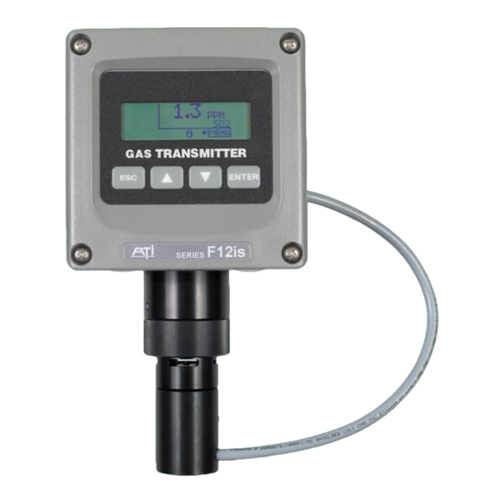
Part1 - Introduction General F12is Gas Transmitter The F12is Gas Transmitter is used to monitor for gas leaks near storage cylinders, process piping, or gas feed equipment in nearly any type of industrial plant environment. It is housed in NEMA 4X, polycarbonate enclosure and features an H10 Smart Sensor, a non-intrusive four button user interface with a backlit transflective graphics display, three level alarms with three (optional) alarm relays, a high-resolution 4-20mA current loop output, real-time clock, data-logger, and optional HART™... -
Page 6: H10 Smart Sensors
Model F12is Gas Transmitter Part 1 - Introduction H10 Smart Sensors Part No. Standard Minimum Maximum Range Range Range GENERAL GASES Acetylene 00-1057 0-200 PPM 0-50 PPM 0-500 PPM Alcohol 00-1043 0-200 PPM 0-50 PPM 0-500 PPM Alcohol 00-1044 0-500 PPM 0-500 PPM 0-2000 PPM Ammonia... - Page 7 Model F12is Gas Transmitter Part 1 - Introduction ACID GASES Hydrogen Bromide 00-1455* 0-20 PPM 0-10 PPM 0-200 PPM Hydrogen Chloride 00-1017* 0-10 PPM 0-10 PPM 0-200 PPM Hydrogen Cyanide 00-1018* 0-10 PPM 0-10 PPM 0-200 PPM Hydrogen Fluoride 00-1019* 0-10 PPM 0-10 PPM 0-200 PPM...
-
Page 8: Specifications
Model F12is Gas Transmitter Part 1 - Introduction Specifications Sensor Type Electrochemical cell Gas Type Sensor dependent (refer to list of available sensor types) Range User adjustable within limits of selected sensor (refer to list of available sensor types) Response Time Sensor dependent Accuracy Generally ±10% of value, but limited by available calibration gas accuracy. -
Page 9: Hazardous Area Approvals
Model F12is Gas Transmitter Part 1 - Introduction Hazardous Area Approvals Approved Models: F12is-1-b-c-d, where: b: 1, 2, 3, 4, 5, 6, 7, or 8 c: 1 or 2 (for b=1, 2, 3, or 4), 1 (for b=5, 6, 7, or 8) d: 1 or 2 UL/CSA - Conforms to UL 913 &... -
Page 10: Control Drawings
Model F12is Gas Transmitter Part 1 - Introduction Control Drawings Figure 2a Control Drawing (DWG: ATI-1042, Sheet 1) O&M Manual ATI P/N 85-0001 Rev E (May 2016) -
Page 11: Figure 3 B Control Drawing
Model F12is Gas Transmitter Part 1 - Introduction Figure 3b Control Drawing (DWG: ATI-1042, Sheet 2) O&M Manual ATI P/N 85-0001 Rev E (May 2016) -
Page 12: Part 2 - Mechanical Installation
Part 2 – Mechanical Installation Transmitter Mounting Threaded inserts in the rear of the enclosure permit the attachment of brackets for securing the transmitter to a wall or pipe. Choose a location so the transmitter display is readily visible, and the panel buttons and sensor are accessible for calibrations. -
Page 13: Wall And Pipe Mounting
Part 2 – Mechanical Installation Model F12 Gas Transmitter Wall and Pipe Mounting A PVC mounting bracket with attachment screws is supplied with the transmitter. The transmitter is attached to the bracket using four flat head screws, and the bracket is attached to a wall or pipe by way of the four slots in each corner. -
Page 14: Figure 7. Pipe Mounting Diagram
Part 2 – Mechanical Installation Model F12 Gas Transmitter Figure 7. Pipe mounting diagram O&M Manual ATI P/N 85-0001 Rev E (May 2016) -
Page 15: Generator Installation/Removal
Part 2 – Mechanical Installation Model F12 Gas Transmitter Generator Installation/Removal Generators are inserted into the optional generator housing attached to the bottom of the sensor housing at the base of the transmitter. Before installing the generator, check to see that the set screw on the side of the holder is loose and does not contact the generator during installation. -
Page 16: Figure 9. Duct-Mount Sensor Holder
Part 2 – Mechanical Installation Model F12 Gas Transmitter Duct Sensor Mounting The H10 sensor duct mount option allows sensors to be installed in a duct or pipe, and provides easy access for service. The assembly is comprised of a special H10 sensor holder (Figure 9) that slides into the hollow duct mount adapter ( Figure 11). -
Page 17: Figure 11. Duct - Mount Adapter
Part 2 – Mechanical Installation Model F12 Gas Transmitter Figure 11. Duct-mount adapter (ATI-0670) Figure 12. Duct-mount assembly O&M Manual ATI P/N 85-0001 Rev E (May 2016) -
Page 18: Part 3 - Electrical Connections
Part 3 – Electrical Connections Transmitter Connections WARNING: Installation must be in accordance with the recognized standards of the appropriate authority in the country concerned. To access the wiring terminals inside the transmitter, loosen the four screws in each corner of the housing’s front cover. -
Page 19: Sensor Adapter Board
Part 4 – Operation Model F12is Gas Transmitter Sensor Adapter Board The Sensor Adapter Board provides a socket connector for the sensor plug and mates to a 14-pin header on the transmitter’s Power Supply board. Wire assignments for the sensor plug are shown below. The board does not normally need to be removed, but if necessary, unplug the sensor and remove the (2) retaining nuts and screw. -
Page 20: Terminal Board
Part 4 – Operation Model F12is Gas Transmitter Terminal Board The Terminal Board is located just below the metal shield in the front cover. It contains the power and communication terminals, and provides a header for connecting the Sensor Adapter board. In addition, the board has a jumper block for configuring the communication interface. -
Page 21: Wiring Examples
Part 4 – Operation Model F12is Gas Transmitter Wiring Examples ATI A17/B14 Receiver(s) Up to two transmitter/receivers may be connected to a single A17 power supply. 8 7 6 5 4 3 2 1 F12 P/S Board A17 Power Supply 115/230VAC B14 Receiver (50/60Hz) -
Page 22: Hart Point-To-Point (2-Wire)
Part 4 – Operation Model F12is Gas Transmitter HART Point-to-Point (2-Wire) The HART “Point-to-Point” connection permits the transmitter to communicate digitally, while retaining the functionality of its 4-20mA current loop. Setting the transmitter’s polling address to 0 permits the current loop to function normally. - Page 23 Part 4 – Operation Model F12is Gas Transmitter Remote Sensor Wiring The remote sensor option permits the sensor to be mounted up to 100’ (MAX) from the transmitter. Remote interconnect cable sold separately. O&M Manual ATI P/N 85-0001 Rev E (May 2016)
-
Page 24: Part 4 - Operation
Part 4 – Operation Model F12is Gas Transmitter Part 4 - Operation 4.1 Operator Interface Panel The F12 operator interface is non-intrusive, so you do not have to remove the housing cover to view the display, configure the transmitter, or calibrate the sensor. It features a transflective 96x32 dot LCD display, and four panel keys. -
Page 25: Figure 19. Example Edit
Part 4 – Operation Model F12is Gas Transmitter Menus and Settings Items appearing on the display are usually text labels that identify the name of a menu or a setting. Menus are typically a single text label, like “Menu”, while settings are typically composed of a text label and a value field separated by an equal sign, like, “Range= 50.0”. -
Page 26: 4.2 Startup
Part 4 – Operation Model F12is Gas Transmitter 4.2 Startup Transmitter Review Start Startup Review ATi Gas Xmtr F12-0-0 Model–rev-id Site name Site name (option) ► ►Hold Next Skip Version HW=X.XX/SW=X.XX Version Lang= English Information ► Communications Modbus/RS485 Communication 9600,N,8,1 Option Settings ►... - Page 27 Part 4 – Operation Model F12is Gas Transmitter Sensor Review Start (Same SIB) (New SIB) ATi Gas Xmtr ATi Gas Xmtr SIB-8-1-1 SIB–model-rev-id SIB-8-1-1 ► ►Verify (New Type Sensor) (Same Type Sensor) (Sensor Missing) Sensor Trouble 24.2 H2S 24.2 H2S Gas number, name, Sensor Removed Range= 10 PPM...
-
Page 28: Figure 22. Generator Normalr
Part 4 – Operation Model F12is Gas Transmitter Generator Review Start Gas number & name Gas Generator Output data 100 PPM H2S Usage data 0.00Hrs of 3.00 ► When the Auto-test status is READY, and no problems are detected with the Auto- Auto- generator, the date and time of the next... -
Page 29: 4.3 Main Display
Part 4 – Operation Model F12is Gas Transmitter 4.3 Main Display The Main Display Page shows the name and concentration of the target gas, and units of measurement (PPM, PPB, %, etc). Indicators on the left and below show alarm and operating status. Over-range/Under-range Gas concentration at or Alarm Indicators... -
Page 30: 4.4 Pop-Up Displays
Part 4 – Operation Model F12is Gas Transmitter Trouble Indication Main Display The Trouble alarm is indicated by four dashes appearing on the Main Display, along with the (!) flag in the lower left corner, and the 4-20mA status icon ---- indicating that the 4-20mA output is fixed (default = 3.6mA). -
Page 31: Figure 27. Generator Removedd
Part 4 – Operation Model F12is Gas Transmitter Sensor Install Effects on the Data Log When the sensor is replaced with one of a different gas type (ie, a different part number), you are also prompted to clear the data log during review. Startup Review Datalog Status Logging is ON... -
Page 32: 4.5 Main Menu
Part 4 – Operation Model F12is Gas Transmitter 4.5 Main Menu Main Menu The main menu provides direct access to the sensor calibration methods, data logger graph, and transmitter settings. Select to … Item Zero >Menu Calibrate the gas sensor zero reading (see Sensor Zero Calibration on page 33). -
Page 33: 4.7 Sensor Menus, Methods, And Settings
Part 4 – Operation Model F12is Gas Transmitter 4.7 Sensor Menus, Methods, and Settings Sensor Menu Select to … Item >Menu >Setup >Sensor Configure the sensor range, damping, and blanking (see Settings Sensor Settings, below). Sensor ►Settings Maintain the accuracy of the gas sensor (see Sensor Calibration Calibration Calibration... -
Page 34: Figure 34. Sensor Range Menu
Part 4 – Operation Model F12is Gas Transmitter Sensor Range Menu Select to … Item …Settings>Range Menu Set the gas concentration value corresponding to the 20mA output value. Changing this value also changes the Blank Settings (blanking) value, which is maintained as a fraction of the range. Range ►Range= 50.0PPM Setting limits vary among sensors. - Page 35 Part 4 – Operation Model F12is Gas Transmitter Sensor Calibration Calibration Frequency While the transmitter itself requires no periodic calibration, H10 sensors should be “zero” and “span” calibrated every 3-6 months, based upon environmental factors. Sensors frequently exposed to dirt, oil mist, vapors, or very dry air, may require more frequent calibration.
-
Page 36: Figure 36. Sensor Calibrationm
Part 4 – Operation Model F12is Gas Transmitter Sensor Calibration Menu Select to … Item …Sensor>Calibration Calibrate the gas sensor zero reading (below). Note – this item Zero also appears in the Main Menu (see Figure 28. Main Menu) Calibration Calibrate the gas sensor sensitivity (below). -
Page 37: Figure 37. Sensor Zero Cal. Setup
Part 4 – Operation Model F12is Gas Transmitter Sensor Zero Calibration Performing a zero calibration requires a bottled “Zero-gas” with a 500 cc/min regulator, calibration adapter, and a convenient length of ¼” tubing. The gas used depends on the type of sensor installed. For example, an H S sensor may be zeroed with Zero-air, however, Oxygen sensors must be zeroed with Nitrogen. -
Page 38: Figure 39 Sensor Span Cal. Setup
Part 4 – Operation Model F12is Gas Transmitter Sensor Span Calibration Span calibration* requires a bottled “span-gas” with a 500 cc/min regulator, calibration adapter, and a convenient length of ¼” tubing. The gas type and concentration used depends on the type of sensor installed. -
Page 39: Figure 41. Sensor Calibrationh
Part 4 – Operation Model F12is Gas Transmitter Sensor Calibration History A calibration record is written into the sensor memory each time a zero or span calibration is performed. Enough memory is reserved for 63 zero calibrations and 63 span calibrations. Zero and span calibration records are accessed on the Sensor Calibration History page. -
Page 40: Figure 42. Auto-Test Menu
Part 4 – Operation Model F12is Gas Transmitter Sensor Auto-test Auto-test verifies the serviceability of the sensor on a prescribed schedule by exposing it to a small amount of gas, and verifying a minimum response. Three attempts per test are made, and if the sensor does not respond on the third attempt, a temporary trouble alarm is triggered (may be optionally disabled). -
Page 41: Figure 43. Auto-Test Setup Menu
Part 4 – Operation Model F12is Gas Transmitter Auto-test Exceptions on page 39 are present. When attempted, the transmitter displays an exception message. Auto-test Setup Menu Select to … Item …Auto-test>Setup Configure the number of days between automatic tests. The default is 1, and the limit is 1 to 14 (the exact time of day for Interval Setup... -
Page 42: Figure 46. Auto - Test Historym
Part 4 – Operation Model F12is Gas Transmitter NextAT Date After Startup During startup, the transmitter examines the NextAT field and advances it by the Day Interval to provide a minimum of 24 hours before the next test is performed. Therefore, it is important to keep the transmitter powered to maintain the desired test Auto-test schedule. -
Page 43: Figure 48. Auto - Test Statusd
Part 4 – Operation Model F12is Gas Transmitter Auto-test Exceptions Auto-test will not start if any of the following conditions are present. Furthermore, Auto-test is immediately aborted when any of the critical exceptions are detected. Non-critical Exceptions The sensor is warming up (animated hour glass visible on main display). ... -
Page 44: Figure 49. Auto - Test Statusd
Part 4 – Operation Model F12is Gas Transmitter Status = START Main Display Status=OFF or READY Update next Auto-test date Resume normal operation MENU Status = START Auto-Test Status Display Time = 0 Auto-test Non-critical start exception ►WAIT 01:00 Time = 0... -
Page 45: 4.8 Alarm Menus, Methods, And Settings
Part 4 – Operation Model F12is Gas Transmitter 4.8 Alarm Menus, Methods, and Settings The transmitter features three gas level alarms - Alarm, Warning, and Caution, and a Trouble alarm. Gas level alarms are automatically configured when a gas sensor is installed, and are retained between same type sensors. -
Page 46: Figure 53. H
Part 4 – Operation Model F12is Gas Transmitter Gas Alarm Operation Figure 53 illustrates the operation of a high (rising) gas level alarm. Set Level Res Level Set Delay Res Delay S e c o n d s Rdg at set level Rdg at reset level Alarm becomes active Alarm becomes inactive... -
Page 47: Figure 55. A
Part 4 – Operation Model F12is Gas Transmitter Alarm Indicators Gas level alarms are indicated by three flags on the left side of the Main Display, each containing a letter indicating the alarm name, and an arrow indicating the type of alarm - high (rising) alarm, or low (falling) alarm. - Page 48 Part 4 – Operation Model F12is Gas Transmitter Alarm Setting Menus The Alarm Setting Menus are accessed from the Alarms Menu and are used to configure the three gas level alarms. >Menu>Setup>Alarms Alarms ►Alarm Inhibit Warning Test Caution …Alarms >Caution …Alarms>Alarm …Alarms >Warning Type=...
- Page 49 Part 4 – Operation Model F12is Gas Transmitter Select how the alarm is reset as Manu or Auto. When set to Auto, the alarm will reset (clear) without operator intervention, as soon as conditions allow (concentration reaches Res Level, and the Res Delay period expires). When set to Manu, the operator must reset the alarm manually after conditions subside, through the operator interface, the serial Reset Remote Reset...
-
Page 50: Figure 59. T
Part 4 – Operation Model F12is Gas Transmitter Trouble Alarm Trouble alarm are presented on the Main Display as shown below. When Main Display active, new alarms are inhibited, and (by default) active alarms are held so that ---- relays controlling lights, sirens, and fans may continue to operate (this behavior may be modified on the Alarms Menu (see pg 41). - Page 51 Part 4 – Operation Model F12is Gas Transmitter Trouble Messages Table 2 describes the trouble messages and lists the corrective action codes, which are listed below. Table 2. Trouble Messages Trouble Description Corrective Action(s) Gas Signal Err The analog-to-digital converter channel assigned to the sensor’s gas concentration output signal has 1-3,4,6,8 failed, or is out of range.
- Page 52 Part 4 – Operation Model F12is Gas Transmitter Trouble Description Corrective Action(s) 3W Pwr Required If relays are not being used, disable them Relays or RS232/485 communication is enabled, but (see Relays Menu on pg 66) transmitter does not have 3-wire power applied. Xmtr Uncal The transmitter’s factory calibration data has 2,3,7...
-
Page 53: Figure 61. A
Part 4 – Operation Model F12is Gas Transmitter Alarm Inhibit Alarms are inhibited to temporarily disable (false) activation and should be re-enabled as soon as possible to maximize the safety of the area. The duration of inhibit period depends the method used to activate it. For example, alarm inhibit occurs automatically during zero and span calibration and expires after 30 minutes. -
Page 54: Figure 62. A
Part 4 – Operation Model F12is Gas Transmitter …Alarms >Test Test Warning: this wi “This will activate alarm relays” ►Alarm= C W A T Start Devices wired to the relays may activate when “Start” is selected. Inform all personnel before performing the test. -
Page 55: 4.9 Data-Log Menus, Methods, And Settings
Part 4 – Operation Model F12is Gas Transmitter 4.9 Data-log Menus, Methods, and Settings The transmitter records gas concentrations in one of 12 intervals ranging from 1 to 60 minutes, providing data from 11 to 474 days. Table 4 details the sampling intervals, and the samples/day and totals days for each interval. -
Page 56: Figure 64. D
Part 4 – Operation Model F12is Gas Transmitter Data Log Setup Menu Settings on the Data Log Setup page select one of the 12 discrete sampling intervals listed in Table 4, and control starting, stopping and clearing of the data-log. Select to …... -
Page 57: Figure 66. D
Part 4 – Operation Model F12is Gas Transmitter Table 5. Data Log Special Codes Special Code Description ---- Sample unavailable (transmitter powered off, or sample not yet recorded) FFFF Trouble alarm active at time of sample TEST Auto-test active at time of sample (if Log_Data=NO, see Auto-test Setup Options Menu) **** Data is corrupted, or unreliable Data Log Graph View... -
Page 58: Figure 68. D
Part 4 – Operation Model F12is Gas Transmitter Data Log Single View The Data Log Single View Menu allows scrolling to an exact date and time for viewing a single sample. Selecting Graph then presents the Graph view at the selected date and time. Select to …... -
Page 59: Figure 70. D
Part 4 – Operation Model F12is Gas Transmitter Data Log Print Menu The Data Log Print Menu appears by selecting Print from the Data Log Menu (pg 51). The data log must not be empty, and the communication protocol must be set to ASCII before entry (see COM Menus on pg 59), or an exception message will be displayed. - Page 60 Part 4 – Operation Model F12is Gas Transmitter An RS232 connection can support full duplex communication and is perfectly suited for XON/XOFF flow control. However, an RS485 connection is only half duplex. It cannot receive while it is transmitting and might miss the XOFF character, resulting in a buffer overflow at the receiving device.
-
Page 61: 4.10 I/O Menus, Methods And Settings
Part 4 – Operation Model F12is Gas Transmitter 4.10 I/O Menus, Methods and Settings I/O Menu The I/O menu is shown below and appears by selecting I/O from the Main Menu (pg 28). Select to … Item 4-20mA Configure and adjust the 4-20mA output. Menu>Setup>I/O Configure the RS232/RS485 serial interface (option). -
Page 62: Figure 76. A
Part 4 – Operation Model F12is Gas Transmitter 4-20mA Adjust Menu These methods permit adjustment of the 4-20mA output and provide a way to force it to a fixed value to test receiver alarms. They do not affect the computed gas concentration reading. Select to …... - Page 63 Part 4 – Operation Model F12is Gas Transmitter COM Menus and Settings The transmitter supports ASCII, HART, and Modbus communications, which are configured through the COM Menu below. COM Menu The is COM Menu used to configure the protocol and connection settings of the serial COM interface, and varies slightly, depending on the factory configured protocol.
- Page 64 Part 4 – Operation Model F12is Gas Transmitter COM Setup Menu The COM Setup Menu is used to select the protocol and configure the transmitter’s connection settings. Select to … Item …COM>Setup Change the slave protocol. ASCII (default) ►Protocol=None ...
-
Page 65: Figure 81. H
Part 4 – Operation Model F12is Gas Transmitter HART The following applies to transmitters that have the HART FSK modem interface and HART FSK firmware option. A HART “point-to-point” connection permits simultaneous digital and analog communication between one or two masters and one slave device. A HART multi-drop connection permits one or two masters and up to 15 devices to communicate digitally, but prohibits analog communication by requiring each slave device to fix its output at its lowest level (4mA). -
Page 66: Figure 82. H
Part 4 – Operation Model F12is Gas Transmitter Item Description …COM >HART>Operation Loop This setting specifies the analog operating mode of the 4-20mA output. When the HART polling address is 0, the value is Not- ►Mode= Not-Fixed Fixed and analog signaling functions normally. When the Fixed mA= address is set to 1 or higher, the value is Fixed and the analog Resp Preamb= 5... -
Page 67: Figure 83. M
Part 4 – Operation Model F12is Gas Transmitter Modbus The following applies to transmitters that have an RS232 or RS485 COM interface and the Modbus firmware option. This option is not permitted on model F12is. Modbus is a master/slave protocol that supports a single master, and up to 247 slave devices on a common bus. - Page 68 Part 4 – Operation Model F12is Gas Transmitter Relay Operation, Menus, and Settings The following applies to F12 transmitters ordered with optional 3 SPST relays. This option is not permitted on model F12is. The F12 Alarm Relay option provides three SPST mechanical relays on the Power Supply board. The relays are rated for 5 amps, non-inductive loads at 250VAC, and are suitable for switching small loads, such as horns and warning lights, but should not be used to switch motors or other high current, inductive loads.
-
Page 69: Figure 84 A
Part 4 – Operation Model F12is Gas Transmitter Figure 84 illustrates the alarm and relay operation. This option is not permitted on model F12is. Relay Logic Alarm (- - - user configurable) Logic Concentration (NO) (NO) (NC) 1 2 3 Sdly Set_Point Active... -
Page 70: Figure 85. R
Part 4 – Operation Model F12is Gas Transmitter Relays Menu The Relays Menu appears by selecting Relays from the I/O Menu (see pg 57) . Select to … Item Active Permanently enable or disable operation of .the relays. Menu>Setup>I/O>Relays Relays Assign each relay to an alarm and select the normal state of its Setup ►Active= No... -
Page 71: 4.11 Panel Menus, Methods, And Settings
Part 4 – Operation Model F12is Gas Transmitter 4.11 Panel Menus, Methods, and Settings Panel Menu Select to … Item Menu >Setup >I/O>Panel Adjust the display contrast or when the backlight comes on. Display Note: backlight operates only when powered in 3 or 4 wire mode. Panel ►Display Security... -
Page 72: Figure 90. S
Part 4 – Operation Model F12is Gas Transmitter Security Menu The transmitter prevents changes to the transmitter configuration through the front panel when security is active. Settings may be read, but not modified, and methods will not execute, including verifications during Sensor Review (see pg 23). -
Page 73: Figure 92. D
Part 4 – Operation Model F12is Gas Transmitter Deactivating Security The following display sequence appears when attempting to deactivate panel security. Note the option for automatically relocking the panel after a timed period. …Panel>Security Security ►Active= Yes Change Code …Security>Code Entry …Security>Code Entry Security Security... -
Page 74: Figure 93. C
Part 4 – Operation Model F12is Gas Transmitter Changing the Security Code The security code is changed by selecting “Change Code” from the Security menu above (Figure 90). …Panel>Security Security Active= ►Change Code …Security>Change Code …Security>Change Code Security Security Code= Fail Old Code= Enter code to . -
Page 75: 4.12 System Menu
Part 4 – Operation Model F12is Gas Transmitter 4.12 System Menu Select to … Item Set or update the transmitter’s real-time-clock. Clock >Menu >Setup >System System Restart the transmitter or change all user settings to default Reset ►Clock Site values. Reset Version Display transmitter and sensor version information. - Page 76 Part 4 – Operation Model F12is Gas Transmitter Version Menu The Version Menu appears by selecting Version from the System Menu above and lists the major components of the transmitter as menu entries. Select to … Item Xmtr >Menu>Setup>System>Version View the transmitter version information. Settings Sensor View the sensor version information.
- Page 77 Part 5 – Maintenance The F12is is virtually maintenance free. Other than the consumable sensor and auto-test generator, the battery backup for the real time clock is the only other user replaceable part. Real Time Clock Battery Replacement WARNING: Disconnect power, and move unit to a non-hazardous area before servicing.
- Page 78 Part 5 – Maintenance Model F12 Gas Transmitter 3. Remove the Internal Shield by removing the three screws (4) 4. Remove the Terminal PCB by pulling straight up, to expose the CPU PCB (5). 5. Remove the Battery (6), and replace with same kind. 6.
-
Page 79: Part 6 - Spare Parts
Part 6 – Spare Parts GAS TRANSMITTER Figure 98 - Exploded View Part No. Description 03-0355 F12 Transmitter Front Lid Assembly 01-0278 Sensor Terminal Board Assembly 03-0331 F12 Sensor Holder Assembly 03-0332 Standard Sensor Cap 00-1537 Auto-Test Generator Holder Assembly 01-0294 Power Supply / Relay Board Assy, AC Version 01-0316... - Page 80 Part 5 – Maintenance Model F12 Gas Transmitter Table 7. H10 sensor modules Part No. Description 00-1000 Bromine, 0-1/5 PPM (2 PPM Standard) 00-1001 Bromine, 0-5/200 (20 PPM Standard) 00-1002 Chlorine, 0-1/5 PPM (2 PPM Standard) 00-1003 Chlorine, 0-5/200 (20 PPM Standard) 00-1004 Chlorine dioxide, 0-1/5 PPM (2 PPM Standard) 00-1005...
- Page 81 Part 5 – Maintenance Model F12 Gas Transmitter 00-1450 Dimethylamine (DMA), 100/200 PPM (100 PPM Standard) 00-1455 Hydrogen bromide, 10/200 PPM (20 PPM Standard) 00-1469 Hydrogen sulfide, 200/1000 PPM (500 PPM Standard) Table 8. E18 gas generators Part No. Description 00-1538 Chlorine 00-1539...
- Page 82 PRODUCT WARRANTY Analytical Technology, Inc. (Manufacturer) warrants to the Customer that if any part(s) of the Manufacturer's products proves to be defective in materials or workmanship within the earlier of 18 months of the date of shipment or 12 months of the date of start-up, such defective parts will be repaired or replaced free of charge.
- Page 83 WATER QUALITY MONITORS GAS DETECTION PRODUCTS Dissolved Oxygen Ammonia Carbon Monoxide Free Chlorine Hydrogen Combined Chlorine Nitric Oxide Total Chlorine Oxygen Residual Chlorine Dioxide Cl2 Phosgene Potassium Permanganate Bromine Chlorine Dissolved Ozone Chlorine Dioxide pH/ORP Fluorine Conductivity Iodine Hydrogen Peroxide Acid Gases Peracetic Acid O Ethylene Oxide...
Need help?
Do you have a question about the F12is Series and is the answer not in the manual?
Questions and answers