Sign In
Upload
Manuals
Brands
ATI Technologies Manuals
Transmitter
d12 series
ATI Technologies d12 series Manuals
Manuals and User Guides for ATI Technologies d12 series. We have
1
ATI Technologies d12 series manual available for free PDF download: User Manual
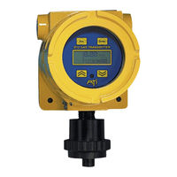
ATI Technologies d12 series User Manual (92 pages)
toxic gas transmitter with H10 smart sensor
Brand:
ATI Technologies
| Category:
Transmitter
| Size: 1 MB
Table of Contents
Product Warranty
2
Table of Contents
3
Introduction
5
Components
5
D12 Toxic Transmitter
5
H10 Smart Sensor and C18 Gas Generator
5
Figure 1. Transmitter, Sensor, Generator
5
Specifications
8
Installation
9
Mechanical Mounting
9
Transmitter
9
Figure 2. Overall Dimensions
9
H10 Sensor Duct-Mount Option
10
Figure 3. Duct-Mount Sensor Holder
10
Figure 4 Duct Mount Sensor Exploded View
10
Figure 5. Duct-Mount Adapter
11
Figure 6. Duct-Mount Assembly
11
Electrical Connections
12
Board Stack
12
Figure 7. Separating the Board Stack
12
Power Supply Board Connections
13
Figure 8. Power Supply Board Connections
13
External Connections
14
ATI A17/B14 Monitor(S), 2-Wire Mode
14
Figure 9. ATI A17/B14 Monitors, 2-Wire
14
ATI A17/B14 Monitor(S), 3-Wire Mode
15
Figure 10. ATI A17/B14 Monitor(S), 3-Wire Mode
15
Power Only, no Output Options
16
Figure 11. Power Only, no Output Options
16
Current Loop Receiver, Single Supply (2-Wire Mode)
17
Figure 12. Current Loop, Single Supply (2-Wire Mode)
17
Current Loop Receiver, Single Supply (3-Wire Mode)
18
Figure 13. Current Loop Single Supply (3-Wire Mode)
18
Current Loop Receiver, Dual Supplies (4-Wire Mode)
19
Figure 14. Current Loop, Dual Supplies (4-Wire Mode)
19
HART Transmitter, Point-To-Point (2-Wire)
20
Figure 15. HART Operation, Point-To-Point (2-Wire)
20
HART Transmitter, Point-To-Point, Active Source (3-Wire)
21
Figure 16. HART Operation, Point-To-Point (3-Wire)
21
Figure 17. HART Transmitter Operation, Multi-Drop
22
Modbus RS485 Multi-Drop
23
Figure 18. Modbus RS485 Multi-Drop Connections
23
Computer RS232
24
Figure 19. Computer RS232
24
Remote Sensor Wiring
25
Figure 20 - Remote H10 Sensor Wiring
25
Duct-Mount Sensor Wiring
26
Figure 21 - Duct Mount Wiring
26
Heater Option for Sensor/Generator Housing
27
Figure 22 - Optional Heated Sensor Wiring
27
CPU Board Configuration
28
Figure 23. CPU Board Configuration
28
Operation
29
Operator Interface
29
Interface Panel
29
Figure 24. Operator Interface Panel
29
Startup Review Sequence
30
Figure 25. Startup Review Sequence
30
Main Display Page
31
Five-Minute Time-Out Rule
31
Esc Key Operation (Main Display Page)
31
Fault Indication (Main Display Page)
31
Figure 26. Main Display
31
Figure 27. Standard Fault Indication
31
Main Reading
32
Variable Editing
33
Figure 28. Variable Editing
33
Sensors and Generators
34
Sensor Setup
34
Sensor Setup Page
34
Figure 29. Sensor Setup Page
34
Figure 30. Data-Log Warning Page
34
Sensor more Page
35
Changing H10 Sensors and C18 Generators
35
Removing Sensors
35
Installing Sensors
35
Figure 31. Sensor "More" Page
35
Figure 32. Sensor Removal
35
Removing Generators
36
Installing Generators
36
Figure 33. Generator Removal
36
Bump-Testing
37
Calibration
38
Calibration Frequency
38
Zero Calibration
38
Span Calibration
38
Calibration Terminology
38
Calibration Kits
38
Indications During Sensor Calibration
38
Calibration Exceptions
38
Zero Calibration Procedure
39
Figure 34. Zero Calibration
39
Span Calibration Procedure
40
Figure 36 Span Calibration
40
Calibration of Duct-Mount H10 Sensors
41
Figure 38. Calibration of Duct-Mount H10 Sensors (ATI-0664)
41
Sensor Calibration Records
42
Figure 39. Sensor Calibration History Page
42
Auto-Test
43
Revision N (7/15
44
Auto-Test Controls
45
Auto-Test Setup
45
Figure 40. Auto-Test Control Page
45
Figure 41. Auto-Test Setup Page
45
Auto-Test Setup Options
46
Next Auto-Test
46
Auto-Test History
47
Auto-Test Sequence
47
Gas Generator Information
47
Figure 42. Auto-Test Sequence
48
Alarms and Relays
49
Gas Concentration Alarms
49
Manual Alarm Reset
49
Remote Reset
49
Figure 43. Default Alarm Relationships for Toxic Gas Sensors
49
Figure 44. Default Alarm Relationships for Oxygen Sensors
49
Figure 45. Manual Alarm Reset
49
Gas Alarm Operation
50
Figure 46. Rising Alarm (Active=Above_Sp, Reset=Auto)
50
Figure 47. Falling Alarm (Active=Below_Sp, Reset=Auto)
50
Gas Alarm Setup
51
Figure 48. Alarm Setup Pages
51
Fault Alarms
53
Corrective Actions
53
Figure 49. Fault Alarm (Main Display)
53
Figure 50. Fault Page
53
Revision N (7/15
54
Revision N (7/15
55
Alarm Relays
56
Figure 51 Alarm Relay Schematic(Default - no Alarms Active)
56
Relays Setup
57
Testing Alarm Relays
57
Relay Test Page
57
Figure 52. Relay Setup Page (Example)
57
Figure 53. Relay Test Page Example
57
Inhibiting Alarms
58
Alarm Inhibit Setup
58
Figure 54. Inhibiting Alarms from the Main Display
58
Figure 55. Alarm Inhibit Setup Page
58
M a Output
59
Output Overrides
59
4-20Ma Setup
59
Figure 56. Current Loop Output Plot
59
Figure 57. 4-20Ma Setup Page
59
4-20Ma Control
60
Loop Adjustment
60
Figure 58. 4-20Ma Control Page
60
Figure 59. Loop Adjustment Pages
60
Data-Log
61
Data-Log Access
61
Data-Log Setup
61
Figure 60. Data Log Access Page
61
Figure 61. Data Log Setup Page
61
Data-Log Graphic Report
62
Data-Log Tabular Report
62
Figure 62. Data Log Graphic Report Page
62
Figure 63. Data Log Tabular Report Page
62
Data-Log Printout
63
Figure 64. Data-Log Printout (Example)
63
Display
64
Display Setup
64
System
65
System Access
65
Real-Time Clock
65
Clock Setup
65
Figure 65. System Access Page
65
Figure 66. Clock Setup Page
65
Security
66
Security Control
66
Activating Security
66
Figure 67. Security Control Page
66
Figure 68. Activating Security
66
Deactivating Security
67
Changing the Password
67
Figure 69. Deactivating Security
67
Figure 70. Changing the Password
67
Communications
68
Communication Setup
68
Communication Setup Page
68
Ascii
69
Hart
69
Figure 71. Communication Setup Page
69
Figure 72. Hart Setup Pages
69
Figure 73. Hart A) Find-Me and B) Device Found Pages
70
Modbus
71
Transmitter Version
71
Figure 74. Modbus Setup Page
71
Figure 75. Transmitter Version Page
71
ATI Series D12 Toxic Gas Transmitter with H10 Smart Sensor
72
Restart
72
Spare Parts
73
Revision N (7/15
74
Revision N (7/15
75
Appendix A
76
Report Format
77
Report Control
77
Printing Data Log Reports
76
Example: Charting a Data Log Report
78
Starting the Report
81
Charting with Microsoft Excel
84
Flow Control
76
Serial Connection
76
Advertisement
Advertisement
Related Products
ATI Technologies D12-17
ATI Technologies D12 EX-IR Series
ATI Technologies D16
ATI Technologies V7750 - Firepro Pcie 1GB DDR3 2PORT Dvi
ATI Technologies PROFINET DL10
ATI Technologies DISCOterm
ATI Technologies DAQ T
ATI Technologies DAQ F
ATI Technologies DISCOTERM S
ATI Technologies DKF-T
ATI Technologies Categories
Video Card
Amplifier
Measuring Instruments
Industrial Equipment
Water Heater
More ATI Technologies Manuals
Login
Sign In
OR
Sign in with Facebook
Sign in with Google
Upload manual
Upload from disk
Upload from URL