Sign In
Upload
Download
Table of Contents
Contents
Add to my manuals
Delete from my manuals
Share
URL of this page:
HTML Link:
Bookmark this page
Add
Manual will be automatically added to "My Manuals"
Print this page
×
Bookmark added
×
Added to my manuals
Manuals
Brands
Palm Manuals
Heat Pump
GH
Installation and operation manual
Palm GH Installation And Operation Manual
Water source geothermal heating & cooling heat pump
Hide thumbs
1
Table Of Contents
2
3
4
5
6
7
8
9
10
11
12
13
14
15
16
17
18
19
20
21
22
23
24
page
of
24
Go
/
24
Contents
Table of Contents
Bookmarks
Table of Contents
Table of Contents
Safety Precautions
1 General
2 Transport and Storage
Components
Wired Controller
1 Display and Button
2 Operating the Unit
3 Week and Clock Setting
4 Timer Setting
Error Code
Installation
1 Installation Information
Installation Method
Dimensions
Electric Connection
1 General
Wiring Diagram
Test Run
1 Preparation
Routine Maintenance
Advertisement
Quick Links
1
Wiring Diagram
Download this manual
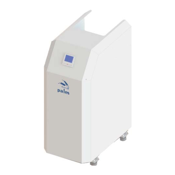
WATER SOURCE GEOTHERMAL
HEATING COOLING HEAT PUMP
Installation and Operation Manual
China Palm A C
/
&
-
GH
Close Loop Series
-
OH
Open Loop Series
/
&
Equipment Co
.,
Ltd
Table of
Contents
Previous
Page
Next
Page
1
2
3
4
5
Advertisement
Table of Contents
Need help?
Do you have a question about the GH and is the answer not in the manual?
Ask a question
Questions and answers
Related Manuals for Palm GH
Heat Pump Palm H Series Installation And Operation Manual
Air to water heat pump (20 pages)
Heat Pump Palm H series Installation And Operation Manual
Air to water heat pump (25 pages)
This manual is also suitable for:
Oh
Table of Contents
Print
Rename the bookmark
Delete bookmark?
Delete from my manuals?
Login
Sign In
OR
Sign in with Facebook
Sign in with Google
Upload manual
Upload from disk
Upload from URL


Need help?
Do you have a question about the GH and is the answer not in the manual?
Questions and answers