
Related Manuals for Palm H Series


Summary of Contents for Palm H Series
- Page 1 DC INVERTER DC INVERTER AIR TO WATER HEAT PUMP H series Only Heating series & AC series Heating Cooling series & HC series Mutifunctional Heating Cooling Hot water Installation and Operation Manual...
-
Page 2: Table Of Contents
Content Safety Precautions General Transport and storage Components Wired LCD Controller Error Code Installation Electric connection Test run... -
Page 3: Safety Precautions
Safety Precautions Note! It is required to read the Safety precautions in detail before operation. The precautions listed below are all-important for safety, please obey without fail. General Make sure that the fixed ground wire in the building is securely connected to earth. Wiring tasks should be carried out by qualified electricians only, in addition, they should check the safety conditions of power utilization, for example, check if the line capacity is adequate, and check if the power cable is damaged. -
Page 4: Components
Components AH-6,AH-8,AH-11,AH-15DC Component Component Position Position Water inlet Evaporator IPM Module Drain Main control board AC Outlet Transformer DHW Outlet Water circulation pump(Optional) Terminal blocks Thermal Expansion Valve Water system control board 4 way valve Needle valve Plate heat exchanger 3 way valve Fan and fan motor Gas liquid isolator... -
Page 5: Wired Lcd Controller
CONTROL PANEL . 1 Wire controller Wire controller contains a LCD and 6 operational keys (as show below). It can keep memory when power off and be a timer. 2. Key functions (1)Double-colored indicator light: when standby, blue light on; when compressor worked, red light on; when breakdown happened, red light on. - Page 6 UNIT OPERATION . 1 Switch the unit On and off To start the unit, press and hold the On/Off key for one second To stop the unit, press and hold the On/Off key for one second . 2 Mode switch(5 modes in total) A.
- Page 7 UNIT OPERATION C. Time setting procedure for health sterilization Only in sanitary hot water mode, health sterilization will work. If sanitary hot water mode off, health sterilization will fail to work. In on or standby mode, first, press key M and for 3 seconds, second, press key M ,15 icon appears, then press the ▲...
- Page 8 . UNIT OPERATION Parameter Checking and setting Please press key M+▲ for 3 seconds and enter to parameter setting mode as show below. “01”is parameter code,“78”is parameter values. Other items’ parameters meaning are the same with above picture showed. Parameter list: Name range/meaning default status...
- Page 9 UNIT OPERATION .7 Machine operational status Checking Press both key M and ▼ for 3 seconds, then entered machine status form. Show as below. “C0”is part or parameter NO. , “28” stands for parameter. Parameter 0 means system on, 1 means system off. For more detail, please check form below.
- Page 10 UNIT OPERATION C4 water pump 1:run;0:stop check C5 water pump 1:run;0:stop check C6 water pump 1:run;0:stop check functional parameter 0-99 check (accumulated days from last legionella until now) Target cooling temp. check Target heating temp check Target hot water temp check Target legionella temp check...
- Page 11 UNIT OPERATION (6)sanitary hot water display (water source heat pump has water source Icon. If it has timer on/off setting, there is timer icon to indicate. ) (7)AC cooling and sanitary hot water display (8)AC heating and sanitary hot water display (water source heat pump has water source Icon.
-
Page 12: Error Code
ERROR CODE When machine has error, the control will show “P” or “E” at AC temp location and show error code at DHW temp location, press key ▼ to search more error codes happened at the same time. Please see table below for error code meaning. Code display like EX or Px, eg: E2、P5 Code Error meaning... -
Page 13: Installation
Installation 1 Installationmethod Method 1 DHW with Room Heating Method 2... - Page 14 Method 3 Method 4 8. Water pump ->C4 1. Heat Pump 9. Drain valve 2. Wired Controller 10. Ball valve 3. DHW water pump 12. Water pump ->C5 4. DHW temp sensor 13. Water pump ->C6 5. DHW water tank 14.
- Page 15 Installation Installation with solar assistant Application 1 Application 2...
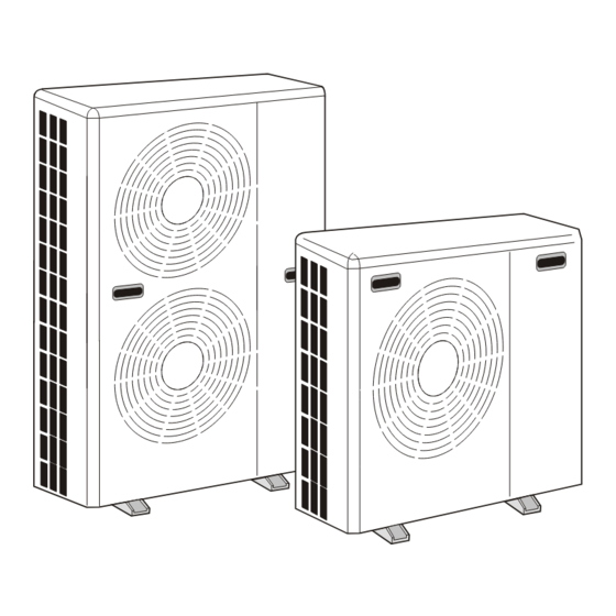
- Page 16 Installation Application 3 The most energy saving application G1 DHW and AC switching valve G2 Solar automatic selection valve 5.4 Unit Dimension(mm) AH-6,AH-8,AH-11,AH-15 Model AH-6,AH-8 AH-11 AH-15 1091 1091 1091...
- Page 17 5.Installation Installation position Note! Installation must be carried out by professional personnel. 1 If the unit is to be installed on the floor, its undercarriage should be heightened, to avoid ingression of accumulated water in rainy season. In snowy areas, it is important to prevent accumulated snow from blocking up the air-out. The recommended height is 20cm to 30cm.
-
Page 18: Electric Connection
Electric connection General Note! Electrical installation and service must be carried out under the supervision of a qualified electrician. Electrical installation and wiring must be carried out in accordance with the stipulations in force. The heat pump must not be connected without the permission of the electricity supplier and must be connected under the supervision of a qualified electrician. - Page 19 Electric connection Wiring Diagram (with built-inside water circulation pump) Wiring Diagram (No built-inside water circulation pump)
-
Page 20: Test Run
Test run Preparation After finish the installation tasks, please check the items: 1 Check the dip switch setting and short wiring 2 Power cable Check if the power cable is connected correctly, and check if the screws have been screwed down. Please use specified cables.
Need help?
Do you have a question about the H Series and is the answer not in the manual?
Questions and answers