Table of Contents
Advertisement
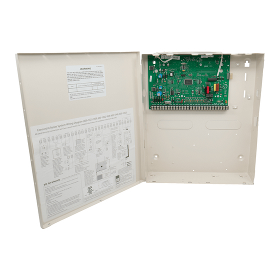
Concord 4 Installation Guide
Content
1
Description 1
4
9
Contact information
For contact information, see www.utcfireandsecurity.com
or www.interlogix.com.
For technical support, toll-free: 888.437.3287 in the US
including Alaska, Hawaii, Puerto Rico, and Canada.
Outside the tool-free area, contact your dealer.
© 2016 UTC Fire & Security Americas Corporation, Inc.
Interlogix is part of UTC Climate Controls & Security, a
unit of United Technologies Corporation.
All rights reserved.
Description
control panel models:
•
600-1021-95R Concord 4 RF
•
600-1022-95R Concord Express V4
•
600-1040 Concord Commercial V4
•
600-1042 Concord Hybrid
This manual provides information for installing a basic
UL Listed Fire and Security System. To modify or use for
other purposes, visit the UTC Fire & Security website for
additional instructions and training.
Table 1 below shows the standard panel capabilities.
P/N 466-2371 • REV D • ISS 19JUL16
Table 1: Panel capabilities
Capabilities
Concord Express v4
Zones
32
Partitions
2
Bus devices
16
User codes
16
Table 2 below describes the basic panel (out-of-box)
hardware capabilities for all panels:
Table 2: Panel hardware capabilities
Pow er
Input for an AC step-down, plug-in style
transformer.
output
amp for bus devices and hardwired detectors,
such as smoke and motion detectors.
Bus A and B
Input and output that provides communication
betw een bus devices and the panel.
Siren driver
Output that can drive an 8-ohm load and provides
intrusion and fire alarm sounds for partition 1 (6
w atts maximum).
Tw o onboard
Can be used to activate other signaling devices
outputs
based on system events. Out 1 is a 9 to 14 VDC
source output, limited to 1.0 amp maximum. Out
2 is an open-collector output, rated up to 14 VDC,
300 mA maximum.
Microphone input
Input used for tw o-way audio w hen used in
conjunction w ith the Interrogator 200 audio
verification module.
hardw ired zones
can be set up in programming to accept tw o-wire
smoke detectors. It sources 9 to 14 VDC, 90 mA
maximum.
Built-in RF
Allow s use of up to 96 or 32 319.5 MHz crystal
receiver
and/or SAW learn mode w ireless sensors and
touchpads.
Concord 4/Concord
Com mercial v4
96
6
16
230
1
Advertisement
Table of Contents

Related Manuals for Interlogix Concord 4 RF


Summary of Contents for Interlogix Concord 4 RF
-
Page 1: Table Of Contents
© 2016 UTC Fire & Security Americas Corporation, Inc. Bus A and B Input and output that provides communication Interlogix is part of UTC Climate Controls & Security, a betw een bus devices and the panel. unit of United Technologies Corporation. -
Page 2: Panel Location
Table 3: Wire length requirements Phone line Allow s panel to communicate w ith central connection monitoring station and/or pagers. Device Max. w ire Standby Alarm m A length to m A draw draw panel Note: The total current sourced from all terminals cannot SuperBus 2000 2x16 LCD 22 ga.: 300 ft. -
Page 3: Mounting The Panel
Device Max. w ire Standby Alarm m A Device Wire requirements length to m A draw draw SuperBus 2000 4-conductor, 22- or 18-gauge panel devices Interrogator AVM 22 ga.: 110 ft. 45 mA 300 mA Interrogator 200 AVM 4-conductor, 22-gauge, shielded 18 ga.: 260 ft. -
Page 4: Programming
The display shows SYSTEM PROGRAMMING. Grounding the panel For maximum protection from lightning strikes and 7. After programming is complete, disconnect the transients, connect the enclosure to earth ground. Use touchpad from the panel header. 16-gauge, solid copper wire from an earth grounded cold Touchpad programming options water pipe clamp to the enclosure. - Page 5 Only when the display shows SYSTEM PROGRAMMING Sensor How to trip the sensor can you advance to tier 2 programming menus. Handheld w ireless Press the BYPASS button. touchpads Press B or # to advance forward through menus. Press A or * to move backward through the menus. Key fobs * Press and hold the lock and unlock buttons together until the key fob LED...
- Page 6 are adding (learning) into the panel memory to send 3. Cycle through the menus as shown in Table 9 a signal to the panel. below. 7. To add another sensor to the same sensor group Table 9: Quick programming menu structure and partition, repeat the process.
-
Page 7: Sensor Group Characteristics
Sensor group characteristics Table 10 below shows what the sensors on your Concord 4 system do. Every sensor is assigned to a group, and this table specifies those groups and functions. Every device must be assigned to one of these groups. The “X”... -
Page 8: Eight Supervised Inputs For Various Hardwired Detectors. Zone
Num ber Nam e Application Alarm Delay Restoral Supervisor Chim e Active report (level) (level) Delayed Interior doors that initiate a delay Police Interior interior before going into alarm Delayed PIR motion sensors that initiate a Police Standard interior delay before going into alarm Local instant 24-hour local alarm zone protecting Police... -
Page 9: Specifications
• Siren verify set to on. • Sleep time set to off. • Control panel (600-1021-95R Concord 4 RF, 600-1022- • Siren timeout set to 4 minutes or more. 95R Concord Express V4, 600-1040 Concord Commercial • Two-trip error set to off. - Page 10 Table 11: SIA setting requirements • UL approved bell/housing, such as Ademco #AB12M or equivalent. Function Default setting Required setting • Immediate beeps set to on. Exit extension • UL 98 options set to on. Duress code Disabled Disabled • Receiver failure set to on (if wireless devices are used).
- Page 11 Note: The installer must verify the compatibility between uses, and can radiate radio frequency energy and, of not this panel and the central station receivers being used. installed and used in accordance with the instruction manual, may cause harmful interference to radio UL Canada listed installations communications.
Need help?
Do you have a question about the Concord 4 RF and is the answer not in the manual?
Questions and answers