
Related Manuals for DSE DSE9460


Summary of Contents for DSE DSE9460
- Page 1 DEEP SEA ELECTRONICS PLC DSE ENCLOSED INTELLIGENT BATTERY CHARGER OPERATOR MANUAL Document Number: 057-176 Author: Anthony Manton DSE ENCLOSED INTELLIGENT BATTERY CHARGER OPERATOR MANUAL ISSUE 2...
- Page 2 DSE Enclosed Intelligent Battery Charger Operator Manual Deep Sea Electronics Plc Highfield House Hunmanby North Yorkshire YO14 0PH ENGLAND Sales Tel: +44 (0) 1723 890099 Sales Fax: +44 (0) 1723 893303 E-mail: sales@deepseaplc.com Website: www.deepseaplc.com DSE Enclosed Intelligent Battery Charger Operator Manual ©...
-
Page 3: Table Of Contents
DSE Enclosed Intelligent Battery Charger Operator Manual TABLE OF CONTENTS BIBLIOGRAPHY ....................5 INSTALLATION INSTRUCTIONS ..................5 MANUALS .......................... 5 SPECIFICATIONS ....................6 PROTECTION ........................7 ELECTRICAL SPECIFICATIONS ..................8 OUTPUT SPECIFICATIONS ....................9 3.4.1 DSE9460 24V/12V 5A ....................9 3.4.2... - Page 4 DSE Enclosed Intelligent Battery Charger Operator Manual FAULT DIAGNOSIS ................... 43 MAINTENANCE, SPARES, REPAIR AND SERVICING ........44 WARRANTY ....................44 DISPOSAL ...................... 44 11.1 WEEE (WASTE ELECTRICAL AND ELECTRONIC EQUIPMENT) ....... 44...
-
Page 5: Bibliography
Bibliography 1 BIBLIOGRAPHY This document refers to and is referred to by the following DSE publications which can be obtained from the DSE website www.deepseaplc.com 1.1 INSTALLATION INSTRUCTIONS Installation instructions are supplied with the product in the box and are intended as a ‘quick start’... -
Page 6: Specifications
Software. NOTE: Chargers are factory preconfigured to suit 12V or 24V batteries (see part numbers above). However a charger can be freely changed from 12V to 24V using DSE Configuration Suite PC Software. NOTE: Chargers are supplied configured to be suitable for Lead Acid batteries. -
Page 7: Protection
Specifications 3.2 PROTECTION • High Output Voltage (DC) detection. • High / Low Input Voltage (AC) detection. • Current limit to charger specification (5A or 10A depending upon charger model) with High Output Current detection. • High Ambient Temperature detection. •... -
Page 8: Electrical Specifications
Specifications 3.3 ELECTRICAL SPECIFICATIONS Parameter Nominal AC Input Voltage (V) 110V-277V 305V Operating Temperature 85°C with de-ratings -30°C Input Frequency (Hz) 48Hz 64Hz Output Ripple and Noise 1% Vo Load Regulation 1% Vo Line Regulation <0.01% Vo Output Voltage Overshoot % <5%Vo Transient Response Peak Deviation (mV) <4% Vo... -
Page 9: Output Specifications
Specifications 3.4 OUTPUT SPECIFICATIONS 3.4.1 DSE9460 24V/12V 5A Parameter Nominal Comments Output Voltage Configurable 29.5V Output Charging Current (A) Current limit threshold (A) Recovery from current limit (A) At Vin=230 V, Vo=28.2 V, Full load AC input current (A) 1.5A Io=5 Amp At Vin=110 V, Vo=28.2 V,... - Page 10 Specifications De-rating Curve 110V < Vin < 305V Charger De-rating Curve Temperature (ºC) De-rating Curve 90V < Vin < 110V Charger De-rating Curve Temperature (ºC)
-
Page 11: Dse9461 24V/12V 10A
Specifications 3.4.2 DSE9461 24V/12V 10A Parameter Nominal Comments Output Voltage Configurable 30.5V Output Charging Current (A) Current limit threshold (A) Recovery from current limit (A) At Vin=230V, Vo=14.4V, Full load AC input current (A) 1.2A Io=10Amp At Vin=110V, Vo=14.4V, Full load AC input current (A) 2.2A Io=10Amp AC Input Inrush (10ms) current... - Page 12 Specifications De-rating Curve 110V < Vin < 305V Charger De-rating Curve Temperature (ºC) De-rating Curve 90V < Vin < 110V Charger De-rating Curve Temperature (ºC)
-
Page 13: Communication Ports
The USB port is provided to give a simple means of connection between a PC and the DSE9400 series battery charger. Using the DSE Configuration Suite Software, the operator is then configure and monitor the state of the battery charger. -
Page 14: Rs485
One advantage of the RS485 interface is the large distance specification (1.2km) when using Belden 9841 (or equivalent) cable. This allows for a large distance between the battery charger and a PC running the DSE Configuration Suite software. The operator is then able to view the various operating parameters. - Page 15 Specifications 3.5.2.1 RECOMMENDED RS485 EXPANSION FOR DESKTOP AND LAPTOP PC’S • Brainboxes PM154 PCMCIA RS485 card (for laptops PCs) Set to ‘Half Duplex, Autogating” with ‘CTS True’ set to ‘enabled’ • Brainboxes VX-023 ExpressCard 1 Port RS422/485 (for laptops and nettop PCs) •...
-
Page 16: Dimensions And Mounting
Specifications 3.7 DIMENSIONS AND MOUNTING Parameter Comment Cabinet type Custom cabinet for indoor use only Overall size 165 mm x 305 mm x 110 mm (see below for diagram) (6.5” x 12” x 4.3”) Material: Sheet steel enclosure of all-round solid construction Surface finish: Powder-coated black IP20... -
Page 17: Applicable Standards
Specifications 3.8 APPLICABLE STANDARDS This document conforms to BS4884-1 1992 Specification for BS 4884-1 presentation of essential information. BS 4884-2 This document conforms to BS4884-2 1993 Guide to content. BS 4884-3 This document conforms to BS4884-3 1993 Guide to presentation. BS EN 60068-2-1 -30°C (-22°F) (Minimum temperature) -
Page 18: Installation
(such as engine cranking). 4.1 BATTERY SUITABILITY The charger is factory set by DSE to suit Lead Acid batteries but can be adjusted to suit other battery types using the Configuration Suite PC Software. -
Page 19: User Connections
230V AC Input 110V AC Input DSE9461 24V/12V 10A charger 3.5A anti-surge 6.3A anti-surge DSE9460 24V/12V 5A charger 2.0A antisurge 3.5A anti-surge 4.2.1 BATTERY CHARGER DANGER OF DEATH: LIVE PARTS exist within the enclosure. The enclosure cover must not be removed when connected to an AC supply. - Page 20 NOTE: Screened 120Ω Ω Ω Ω impedance cable specified for use with RS485 must be used for the RS485 link. DSE stock and supply Belden cable 9841 which is a high quality 120Ω Ω Ω Ω impedance cable suitable for RS485 use (DSE part number 016-030)
-
Page 21: Typical Connection Diagram
Installation 4.2.2 TYPICAL CONNECTION DIAGRAM... -
Page 22: Dse2541 Enclosure Mounted Display Module
NOTE: Screened 120Ω Ω Ω Ω impedance cable specified for use with RS485 must be used for the RS485 link. DSE stock and supply Belden cable 9841 which is a high quality 120Ω Ω Ω Ω impedance cable suitable for RS485 use (DSE part number 016-030) -
Page 23: Indications
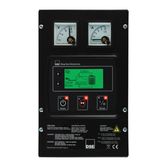
Operation 5 INDICATIONS 5.1 LCD DISPLAY NOTE: LCD display is fitted only to the following model numbers : 9460-01, 9460-02, 9461- 01, 9461-02 NOTE: For details of controls and LCD indication, see the section entitled Operation elsewhere in this document. Charger status LED Fault status LED Boost Mode LED... -
Page 24: Enclosure Mounted Leds
Operation 5.2 ENCLOSURE MOUNTED LEDS NOTE: - Enclosure mounted LED indicators are fitted only to the following model numbers : 9460-03, 9460-04, 9461-03, 9461-04 FAULT 1 LED OPE LED (Operation) FAULT 2 LED 5.2.1 STATUS LED DESIGNATION Condition FAULT 1 FAULT 2 Yellow/Green Yellow... -
Page 25: Fault Conditions
Operation 5.2.3 FAULT CONDITIONS LED DESIGNATION Condition FAULT 1 FAULT 2 High Output Voltage (DC) Constant High / Low Input Voltage (AC) or High Output Current (DC) Flashing High Ambient / Charger Temperature, High Battery Temperature (if enabled) Constant Short Circuit/ Reverse Polarity (DC Output Connection) Flashing 5.3 ENCLOSURE MOUNTED ANALOGUE METERS NOTE: - Enclosure mounted analogue meters are fitted only to the following model... -
Page 26: Operation
Operation 6 OPERATION The DSE battery charger can be used as a battery charger, DC power supply, or both at the same time. For instance, the unit can be used to power the generator control panels and charge the panel batteries or starter batteries at the same time. -
Page 27: Boost Mode
Operation Charging time Charge time is often of little consequence when the battery is used in a standby operation. An example of this is when the battery is used to supply the starting system of a diesel generator. During normal operation, the battery is at full capacity and the battery charger is used to maintain the float voltage of the battery. -
Page 28: Battery Temperature Compensation
Operation Battery Temperature Compensation (Configured to 24V) Temperature (ºC) Calcium Lead Acid Antimony VRLA-AGM VRLA-AGM Wet (Vented) Lead Acid NiCd 10/20 Cell NiCd-9/18 Cell... - Page 29 Operation Battery Temperature Compensation (Configured to 12V) 14.5 13.5 12.5 11.5 Temperature (ºC) Calcium Lead Acid Antimony VRLA-AGM VRLA-GEL Wet (Vented) Lead Acid NiCd 10/20 NICd 9/18...
-
Page 30: Operation Of Lcd Display
01, 9461-02 NOTE: An external remotely connected LCD display can be added to models without the enclosure mounted display. DSE Part Number 2541-02. 6.2.1 BACKLIGHT The LCD backlight is ON while the module is powered and flashes up detection of an alarm condition. -
Page 31: Summary Screen
Operation 6.2.4 SUMMARY SCREEN The Summary Screen is initially displayed when the charged is turned on, and subsequently after a period of inactivity. Link icon Battery charge current Charge graphic to show charge mode Battery icon to show charge state Mains (utility) supply instrumentation... -
Page 32: Charge Graphic
Operation 6.2.7 CHARGE GRAPHIC The LCD shows the charge graphic to show the selected charge curve. The currently active mode is shown flashing in the module display. 6.2.7.1 THREE STAGE CHARGE PROFILE Flashing to show charge mode Detail of charge curve display Absorption charge mode Boost (Bulk) charge... - Page 33 Operation 6.2.7.2 FOUR STAGE CHARGE PROFILE Flashing to show charge mode Detail of charge curve display Absorption charge mode Boost (Bulk) charge mode Storage charge mode Float charge mode NOTE: - A description of each charge mode is given earlier in this manual.
-
Page 34: Viewing The Instrumentation
Operation 6.2.8 VIEWING THE INSTRUMENTATION Press the navigation buttons (up) and (down) to cycle through the available instrumentation screens. All instrumentation screens have the following common icons : Instrumentation area Link icon Battery icon Charge graphic Battery charge current Instrumentation screen type icon An icon is used to show the meaning of the currently visible screen as shown in the following sections. - Page 35 Operation 6.2.8.3 PRODUCT INFO Shows model and firmware version of currently connected battery charger. Product info screen icon 6.2.8.4 CONTROL MODE Shows current operating mode Control mode screen icon Control State Icon displayed Boost...
- Page 36 Operation 6.2.8.5 ALARMS When a new alarm is detected, the LCD displays the alarm screen and the LCD backlight flashes. Press the () button to accept the alarm, exit the alarm screen and return to the summary screen. Shows current alarm condition Alarm screen icon Alarm condition...
-
Page 37: Front Panel Editor
Operation 6.3 FRONT PANEL EDITOR 6.3.1 ACCESSING THE FRONT PANEL EDITOR The front panel editor (FPE) is accessed by pressing and holding the () button. During the transfer of the configuration file from the battery charger to the display module, the File Transfer progress screen is displayed. -
Page 38: Front Panel Editor Parameters
Operation 6.3.3 FRONT PANEL EDITOR PARAMETERS 6.3.3.1 PAGE 1 – MISCELLANEOUS Index Configuration item Icon Contrast Temperature Units Slave ID Baud Rate Enable Alarm Splash Screen Page Timout Screen Page Timeout Sleep Mode Timeout Digital Input Function Battery Voltage Battery Self Test Enabled Battery Self Test Timer Battery Detection Enabled Battery Detection Rate... - Page 39 Operation 6.3.3.2 PAGE 2 – BATTERY TEMPERATURE Index Configuration item Icon Battery Temperature Sensor Enable Battery Temperature Warning Alarm Enable Battery Temperature Warning Alarm Trip Battery Temperature Warning Alarm Delay Battery Temperature Warning Return Battery Temperature Warning Return Delay 6.3.3.3 PAGE 3 – BATTERY OPTIONS Index Configuration item Icon...
- Page 40 Operation 6.3.3.5 PAGE 5 – MAINS Index Configuration item Icon Mains Over Voltage Enable Mains Over Voltage Alarm Trip Mains Over Voltage Alarm Trip Delay Mains Over Voltage Alarm Return Mains Over Voltage Alarm Return Delay Mains Under Voltage Enable Mains Under Voltage Alarm Trip Mains Under Voltage Alarm Trip Delay Mains Under Voltage Alarm Return...
-
Page 41: Modbus
7.1 READING VALUES Values must bre read using Modbus Function Code 3 – Read Multiple Registers. Using the DSE Configuration Suite PC Software, modbus registers are defined by the system designer in modbus Page 166. An example of customer configuration is shown below, the screen image is take from the SE... -
Page 42: Writing Values
Operation Modbus parameter Value Modbus Register Address Page 166 Start Absolute HexaDecimal Address A600 Absolute Decimal Address 42496 (166 x 256). NOTE: Some Legacy Modbus Master devices may require a suffix of 40,000 to the address, making the base address 82496. NOTE: Some Modbus Master devices may require ‘1’... -
Page 43: Fault Diagnosis
Operation 8 FAULT DIAGNOSIS Nature of problem Suggestion Check that the incoming AC supply is correctly connected and within limits and check the integrity of any external fuse that may be fitted. The charger is not operating Ensure the charger is not being operated above the maximum temperature specification. -
Page 44: Maintenance, Spares, Repair And Servicing
Maintenance, Warranty and Disposal 9 MAINTENANCE, SPARES, REPAIR AND SERVICING The DSE battery chargers are designed to be Fit and Forget. As such, there are no user serviceable parts. In the case of malfunction you should contact your original equipment supplier (OEM). - Page 45 This Page is Intentionally Left Blank.
- Page 46 This Page is Intentionally Left Blank.
- Page 47 24v 10A (LED & Meters) 9461-13 SHOCK 24v 10A (LED) 9461-14 a PC (using the free DSE PC BS EN 60068-2-27 Three shocks in each of three major axes configuration suite software) and can 15 gn in 11 mS be configured with pre set charging curves for different battery types.
- Page 48 External remote LCD option through high load conditions. RELATED MATERIALS TITLE PART NO’S DSE9000 Configuration Suite PC Software Manual 057-159 DSE Configuration Suite Installation & Operator Manual 057-151 DSE9460/DSE9461 Series Installation Instructions 053-148 DSE9460/DSE9461 Series Operator Manual 057-176 DSE2541 Data Sheet...
- Page 49 Operating Temperature -30°C to 55°C The charger is factory set by DSE to suit Lead Acid batteries. The DSE91xx & DSE92xx battery chargers can be adjusted at the time (-22°F to 131°F) of ordering to suit other battery types. The DSE947x MKII & DSE948x MKII battery chargers are configured using the DSE Configuraiton Suite to suit other battery types.
- Page 50 Fax: +1 (815) 316- 8708 Fax: +44 (0)1723 893303 NOTE : This document is intended as a ‘quick start’ guide only. For full operating instructions and Email: sales@deepseaplc.com Email: sales@deepseausa.com specifications, refer to DSE publication: 057-085 DSE9xxx Series Operator Manual Web: www.deepseaplc.com Web: www.deepseausa.com...
Need help?
Do you have a question about the DSE9460 and is the answer not in the manual?
Questions and answers