Table of Contents
Advertisement
Quick Links
Form Factor
3.5" Compact Board
Video
Dual Channels 24-bit
LVDS/ Analog RGB/
TV-out
I/O
Mini-PCI/ Mini-Card/
SATA/ USB/ COM/ LPT/
DIO
♦ Technical Support
If you have any technical difficulties, please consult the user's manual first at:
ftp://ftp.arbor.com.tw/pub/manual
Please do not hesitate to call or e-mail our customer service when you still can not
find out the answer.
http://www.arbor.com.tw
E-mail: info@arbor.com.tw
Declaration of Conformity
FCC Class A
This device complies with Part 15 of the FCC Rules. Operation is subject to the
following two conditions : (1) this device may not cause harmful interference, and
(2) this device must accept any interference received, including interference that
may cause undesired operation.
Copyright
2011 All Rights Reserved.
®
EmCORE-i2709
CPU
Soldered onboard Intel®
Atom™ N270 1.6GHz
Processor
LAN
2 x Realtek 8111 PCIe
Gigabit Ethernet
3.5" Compact Board
Quick Installation Guide
- 1 -
Version 1.2
Chipset
Intel® 945GSE
Intel® ICH7M
Audio
Realtek ALC655 AC97
Audio CODEC, Line-in/
Line-out/ Mic-in
4041270900120P
Advertisement
Table of Contents

Related Manuals for ROHS EmCORE-i2709


Summary of Contents for ROHS EmCORE-i2709
-
Page 1: Quick Installation Guide
EmCORE-i2709 3.5" Compact Board Quick Installation Guide Version 1.2 Form Factor Chipset 3.5" Compact Board Soldered onboard Intel® Intel® 945GSE Atom™ N270 1.6GHz Intel® ICH7M Processor Video Audio Dual Channels 24-bit 2 x Realtek 8111 PCIe Realtek ALC655 AC97 LVDS/ Analog RGB/... -
Page 2: Packing List
Packing List Before you begin installing your Compact Board, please make sure that the following materials have been shipped: 1 x EmCORE-i2709 3.5" Compact Board with heat sink 1 x Driver CD 1 x Quick Installation Guide If any of the above items is damaged or missing, contact your vendor immediately. -
Page 3: Specifications
Windows 7 Driver Path CHIPSET \CHIPSET\INF 9.11 Windows 7 built-in LAN driver \GRAPHICS\INTEL_WIN7_32\1930 AUDIO \AUDIO\REALTEK_AC97\Win7_32_64_6305 Specifications Form Factor 3.5" Compact Board Intel® Atom™ N270 CPU 1.6GHz with 533MHz FSB Chipset Intel® 945GSE + Intel® ICH7M 1 x 200-pin SO-DIMM Socket Up to 2GB DDR2 533MHz System Memory SDRAM (Bottom side) VGA/ LCD... -
Page 4: Board Dimensions
Board Dimensions Top View 6.50 Battery 3.17 11.30 -21.60 21.97 98.78 101.96 - 4 -... -
Page 5: Bottom View
Bottom View 32.80 98.57 Unit: mm - 5 -... - Page 6 Jumpers/ Connectors Quick Reference Jumpers Label Function JAT1 AT/ATX Power Mode Selection JBAT1 Clear CMOS Setting JRS1 COM2 RS-232 / 422 / 485 Selection JVLCD1 LCD Voltage Selection Connectors Label Function AUDIO1 Audio Connector COM1 RS-232 Connector COM2 RS-232/422/485 Connector CON1 RS-422/485 Connector CPUFAN...
-
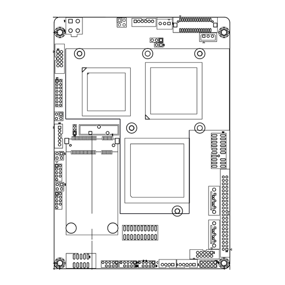
Page 7: Jumpers & Connectors Location
Jumpers & Connectors Location JVLCD1 CPUFAN PWR1 LVDS1 JAT1 JFRT2 JSMB1 COM1 SO-DIMM (on Bottom Side) 9 10 Intel North Bridge VGA1 945GSE Intel Atom SATA2 N270 16 15 JFRT1 SATA1 JBAT1 Battery EKBMS1 LPT1 LLED2 Intel LAN2 South Bridge ICH7M 9 10 LLED1... - Page 8 Jumpers Connectors JVLCD1: LCD Panel Voltage Selection (4) LVDS1: LVDS LCD Connector (1) The voltage of LCD panel could be selected by Connector type: DF-13-30DP-1.25V connector and supports 24-bit dual channels JVLCD1 in +5V or +3.3V. Connector type: 2.54mm pitch 1x3-pin headers. Pin Desc.
- Page 9 JFRT2: LED Indicators (5) JFRT1: Switch (10) This connector provides signals for LED indicators This connector provides signals for the system power presenting the status of the system. switch and reset. Connector type: 2.54mm pitch 2x2-pin headers. Connector type: 2 .54 mm pitch 2x2 pin headers Pin Description Pin Description Pin Description...
- Page 10 JLPC1: Low Pin Count Connector (18) INV1: LCD Inverter Connector (25) Connector type: 2.00mm pitch 1x5-pin box wafer Connector type: 2.00mm pitch 2x10-pin headers connector. Desc. Desc. Description +12V LFRAME Backlight on/off LRESET Brightness control LAD3 LAD2 +3.3V LAD1 DIO1: Digital I/O Connector (26) LAD0 DIO1 is a 8-bit DIO connector w/ onboard 10-pin headers, supports programmable Input / Output.
- Page 11 LPT1: Parallel Port or FDD Connector (29) JSMB1: External SMBus Connector (32) Connector type: 2.00 mm pitch 2x10-pin headers Connector type: 2.54mm pitch 1x3-pin box wafer It can be selected by LPT or FDD mode via BIOS. connector. Description Data Clock Pin Description Pin Description...
- Page 12 This page is intentionally left blank. - 12 -...
Need help?
Do you have a question about the EmCORE-i2709 and is the answer not in the manual?
Questions and answers