Table of Contents
Advertisement
Haas Technical Publications
HAAS SERVICE AND OPERATOR MANUAL ARCHIVE
HRT Operator Manual 96-5047 RevL English June 2005
•
This content is for illustrative purposes.
•
Historic machine Service Manuals are posted here to provide information for Haas machine owners.
•
Publications are intended for use only with machines built at the time of original publication.
•
As machine designs change the content of these publications can become obsolete.
•
You should not do mechanical or electrical machine repairs or service procedures unless you are qualified
and knowledgeable about the processes.
•
Only authorized personnel with the proper training and certification should do many repair procedures.
WARNING: Some mechanical and electrical service procedures can be
extremely dangerous or life-threatening.
Know your skill level and abilities.
All information herein is provided as a courtesy for Haas machine owners
for reference and illustrative purposes only. Haas Automation cannot be held
responsible for repairs you perform. Only those services and repairs that are
provided by authorized Haas Factory Outlet distributors are guaranteed.
Only an authorized Haas Factory Outlet distributor should service or repair a
Haas machine that is protected by the original factory warranty. Servicing by
any other party automatically voids the factory warranty.
Manual_Archive_Cover_Page Rev A
June 6, 2013
Advertisement
Table of Contents
Troubleshooting

Summary of Contents for Haas+Sohn HRT 160
- Page 1 Manual_Archive_Cover_Page Rev A June 6, 2013 Haas Technical Publications HAAS SERVICE AND OPERATOR MANUAL ARCHIVE HRT Operator Manual 96-5047 RevL English June 2005 • This content is for illustrative purposes. • Historic machine Service Manuals are posted here to provide information for Haas machine owners. •...
- Page 2 Back 1. INTRODUCTION 1.1 D ESCRIPTION The HAAS rotary table is a fully automatic, programmable, rotary positioning device. The unit is made up of two parts: the mechanical table that holds the workpiece and the electronic unit that controls the rotation of the table.
- Page 3 1.2 L IMITATIONS The control and table are described as a “semi-fourth axis”. This means that the table cannot do simultaneous interpolation with other axes. Linear moves or spirals can be generated by having an axis of your mill move at the same time the rotary table moves (see the "Programming"...
- Page 4 AC SERVO DRIVE* Closed loop 3.0HP (HA5CHD, HRT 160, HRT 210), 5.0 HP (HRT 310, HRT 450, HRT 600), 1.5 HP (HA5C) DC SERVO DRIVE Closed loop 0.5 HP(HRT160, HA5C), or 1.5 HP(HRT210, HRT310, HRT450, HRT600). VARIABLE FEED RATES* Variable from .001 deg./sec. to 100 deg./sec (100 deg./sec. for HRT160 and HRT320FB, 75 deg./sec. for HRT210, 60 deg./sec.
- Page 5 OPTIONAL RS-232 INTERFACE For computer control of sending and receiving programs. 12-MONTH WARRANTY Against any defects in materials or workmanship. SYNTHETIC GEAR OIL Provides greater worm gear wear protection than conventional gear oils. *Except HRT210SHS; see below: HRT210SHS EATURES XCLUSIVE TO THE Harmonic Drive gear set.
- Page 6 1.5 S PECIFICATIONS . t f b l / s / . ° 0 . t f b l / l i b y t i t u l t u l ) " i T ( t l e e l l l a t i n i...
- Page 7 1.6 M ACHINE IMENSIONS MODEL DIMENSIONS +0.0005 HRT160 160 mm (6.30") 1.50 5.50 16.20 3.63 5.000 ±0.001 4.50 Ø1.50 10.4 HRT 210 210 mm (8.27") 1.75 5.84 17.80 4.63 6.000±0.001 5.25 Ø2.00 +0.0005 12.4 HRT210 (Brush) 210 mm (8.27") 1.75 5.84 20.00 4.63...
- Page 8 HRT SP D IMENSIONS WRENCH ACCESS 0.530” W x 0.50” DP Front & Rear Tie Down Slots MODEL DIMENSIONS HRT 160SP 10.80” 12.25” 10.39” 8.63” 5.000” ±0.001” 4.78” 1.500∅ x 6.00 Depth HRT 210SP 12.28” 13.77” 12.39” 10.64” 6.000” ±0.001” 5.26”...
- Page 9 HRT210SHS M ACHINE IMENSIONS 96-5047 rev L June 2005...
- Page 10 1.7 O PTIONAL ERVO ONTROL RACKET Designed to work specifically with the Haas line of CNC mills. This bracket keeps the Servo Control in easy reach of the operator, allowing for easy programming between the Haas mill and Rotary table. Contact your Haas dealer to order.
- Page 11 Slack must be provided for your machine's movements. If the cable is cut, the motor will fail prematurely. Secure the HRT Rotary Table to your machine’s T-Slot table as shown below. NOTE: The HRT 160, 210, 450, and 600 Rotary Tables can be secured as shown: 1/2-13UNC T-Nuts, Studs, Flange nuts and Washers*...
- Page 12 SEMI-FOURTH AXIS OPERATION RS232 PORT OR TO MILL INTERFACE CABLE PORT SERVO DISP DISP CONTROLLER 4TH AXIS FULL-FOURTH AXIS OPERATION TO MILL 4TH AXIS PORT 4TH AXIS Note: Your HAAS mill must have the 4th axis option to run full-fourth and must be configured as brush or brushless to be compatible with your indexer.
- Page 13 5. If adding an indexer to a Haas mill the settings must be set for the specific table. Refer to the instructions in the mill manual or call the Haas service department. 6. Semi-Fourth Axis: Secure the servo control in servo pendant bracket (Haas part number SCPB) as seen at the end of the introduction section.
- Page 14 2.2 I NTERFACING TO THER QUIPMENT Semi-Fourth Axis Operation Interfacing is an unfriendly word that inspires fear in most non-electrical people. In reality, you are interfacing objects all the time. Hooking up a stereo, computer, or VCR requires many connections, or interfaces. Plug- ging a lamp into the wall and turning the switch on is really interfacing a 100 watt incandescent lamp up to a 15 Megawatt generating plant.
- Page 15 The RS-232 interface sends and receives seven data bits, even parity, and two stop bits. The data rate can be between 110 and 19200 bits per second. When using RS-232, it is important to make sure that Parameters 26 (RS-232 Speed) and 33 (X-on/X-off Enable) are set to the same value in the controller and PC. Parameter 12 must be set to 3 in order to coordinate mill and controller motion.
- Page 16 RS-232 Responses The xP command is presently the only command that responds with data. It will return a single line consisting xnnn.nnn (servo at standstill at position nnn.nnn) OR xnnn.nnnR (servo in motion past position nnn.nnn) OR (servo is off with reason n) OR (servo HOME position lost with reason n) 2.4 T EMOTE...
- Page 17 Figure 2. A Typical CNC Interface. Cycle Finish If your application is in an automatic machine, such as a CNC mill, the feedback lines (pins 1 and 2) should be utilized. Pins 1 and 2 are connected to the contacts of a relay inside the control and have no polarity or power on them.
- Page 18 2.5 R EMOTE PERATION WITH ANUAL QUIPMENT The remote connection is used when you wish to index the unit other than by the START switch on the front panel. This frees the operator from having to touch the control to start indexing. For example, using our optional remote quill switch (Haas P/N RQS) for Bridgeport milling machines, every time the quill handle is retracted it touches a micro switch on the clamp and the indexing head will rotate automatically.
- Page 19 2.7 R FANUC CNC C EMOTE PERATION WITH A ONTROL FANUC control set-up requirements There are several requirements that must be met before a Haas Servo Control can be interfaced with FANUC controlled mill. These are as follows: 1. FANUC control with custom macro enabled and parameter 6001, bits 1 and 4 set to “1”. 2.
- Page 20 Haas parameters Once the above requirements have been met you can revise the parameters of the Haas control. Listed below are the parameters that will need to be changed. Parameter 1= 1 Parameter 2 = 0 Parameter 5 = 0 Parameter 8 = 0 Parameter 10 = 0 Parameter 12 = 3*...
- Page 21 RS 232 Command Blocks: DPRNT[ ] Clear / Reset receive buffer DPRNT [ZGnn ] Loads G-code nn into step no. 00, “0”is a place holder DPRNT[ ZSnn.nnn ] Loads Step Size nnn.nnn into Step no. 00 DPRNT[ ZFnn.nnn ] Loads Feed Rate nnn.nnn into Step no. 00 DPRNT[ZLnnn] *Loads Loop Count into Step no.
- Page 22 2.8 U PLOAD OWNLOAD The serial interface may be used to upload or download a program the same as with almost any other CNC in use today. All data is sent and received in ASCII code. Lines sent by the controller are terminated by a carriage return (CR) and line feed (LF).
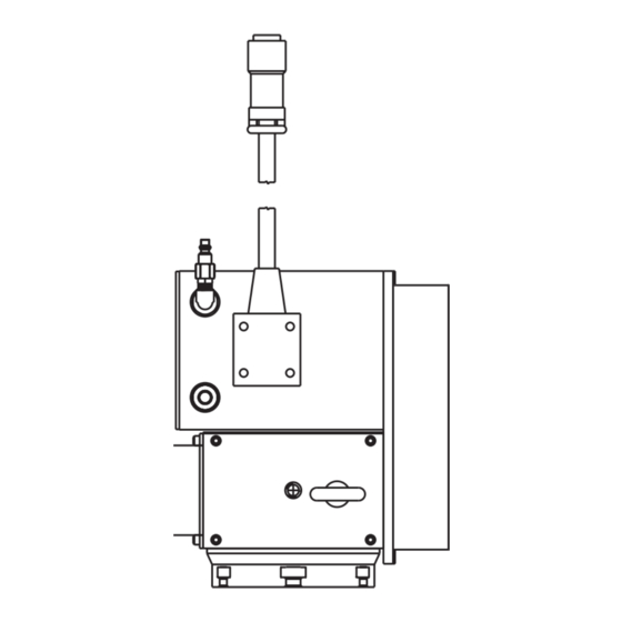
- Page 23 2.9 HAAS A6AC A OLLET LOSER The A6AC collet closer easily bolts to the back of the HRT A6 (see Figure 1a). The drawbar and collet adapters are designed to mate with the Haas A6/5C spindle nose. The optional A6/3J and A6/16C may be obtained from your local tooling distributor.
- Page 24 Clamping Force and Air Supply The A6AC is a 1-3/4 diameter thru-hole type closer which is adjustable from the rear. It holds parts by utilizing spring force to provide up to 0.125 of longitudinal movement and up to 5000 lbs. of draw force at 120 PSI shop air pressure.
- Page 25 3. OPERATION 3.1 T RONT ANEL ISPLAY The Light Emitting Diode (LED) front panel display tells you what is going on inside the controller. There are nine characters that are displayed. The left two characters are the step number and go from 1 to 99. They cannot be changed with the numeric keys and are selected by using the STEP SCAN arrow buttons.
- Page 26 A) Main POWER switch to turn the unit on (back panel). B) CYCLE START begins a step, stops a continued operation, inserts a step, or turns the servo on. C) EMERGENCY STOP turns off the servo when on and aborts the step in progress. D) JOG causes the servo to move in either the forward or backward direction at a rate defined by the last numeric key pressed.
- Page 27 3.2 T URNING ERVO There is a single 115V AC @ 15 amp supply required by the controller. Ensure that the front panel power switch is turned off (Brushless units have the power switch on the rear) and connect the motor cable from the table and the power cord.
- Page 28 Jogging of the motor can be done with the front panel JOG switch. The jog speed is selected with the front panel number keys and is a fraction of the maximum feed rate set by the parameters. The jog speeds (for the HRT 160) are: Number pressed Speed (% of maximum) Jog speed (for 80 deg/sec max.)
- Page 29 0 too SL (Zero margin too small) Zero margin too small is the distance between the home switch and the final stopped motor position, after seeking home, is either less than 1/8 or greater than 7/8 of a motor revolution. This alarm may occur while homing the rotary table.
- Page 30 4. PROGRAMMING THE CONTROLLER 4.1 I NTRODUCTION Programming is done through the square 15-key keypad on the right side of the front panel. The three buttons on the right column of the keypad are used for program control. They are the: MODE / RUN PROG button, DISPLAY SCAN (RIGHT ARROW) button STEP SCAN (UP/DOWN ARROWS) button...
- Page 31 4.3 E NTERING To enter a step into the controller's memory, press the MODE button. This will put the controller into the PROGRAM mode. The display will begin blinking and show a step size. Clear the last program by pressing and holding the CLR key for three seconds.
- Page 32 To display the additional codes associated with a step, press the right arrow key. Possible data entry in- cludes: Step size (no code letter but possible minus sign), Feed rate (F), Loop count (L), G code (G), and Subroutine jump destination step number (Loc). Some of these entries are not allowed for particular G codes and either cannot be entered or are ignored.
- Page 33 ATES The feed rate display ranges between 00.001 and 080.000 (Maximum 080.000 for HRT 160, 060.000 for HRT 210, 050.000 for HRT 310, and 050.000 for HRT 450), preceded by an F. It displays the feed rate that will be used for the selected step.
- Page 34 4.12 A ONTINUE ONTROL If Parameter 10 is set to 2, the controller can be run like a single axis CNC. The entire program will be ex- ecuted until the last step is encountered. In all cases, the last step is the one with a G99. Actually, the step preceding the G99 is the last one to be executed.
- Page 35 4.18 O PERATING INTS 1. You can select another display while in the RUN mode by pushing the DISPLAY SCAN button. This way you could view the particular feed rate for a step or view the remaining loop counts left. 2.
- Page 36 Therefore, if you set the indexer to step 72 degrees (72 ) at a feed rate of five degrees (5 ) per second you will have to program your mill to travel 1.500 inches at a feed rate of 6.25 inches per minute for the spiral to be generated.
- Page 37 5. PROGRAMMING EXAMPLES Example #1 We want to index the platter 90 degrees (90 1. Turn [POWER] switch on. (The power switch is located on the rear panel.) 2. Push the [CYCLE START] switch. 3. Push the [ZERO RETURN] switch. 4.
- Page 38 Example #2 Continuing the previous example, we want to index the platter 90 degrees (Step 1), rotate at five degrees/sec (F5) in the opposite direction for 10.25 degrees (Step 2), and then return home (Step 3). Push the [MODE] button. Displays blinking. Push the [DOWN ARROW] once.
- Page 39 The following examples show the program as you would enter it into the control. We will assume each time that you have cleared out the memory. The bold-face type surrounded by [ ] indicates data that you would enter into the controller. Example #3 We want to drill a four-hole pattern, and then a five-hole pattern on the same part.
- Page 40 This is the same program (Example #5) using subroutines. STEP STEP SIZE FEED RATE LOOP COUNT G CODE LOC [4] [96] 080.000 [88] 080.000 [95] [90.00] 080.000 [91] [15.00] [25.000] [91] 080.000 [99] Explanation: Step #1 tells the control to jump to Step #4. The control will do steps #4 and #5 three times, with Step #6 marking the end of the subroutine.
- Page 41 6. PROGRAMMABLE PARAMETERS There are 37 stored parameters (46 for brushless units) associated with each servo controller. There is a battery in the controller which will keep the parameters (and the stored program) saved for up to eight years. These parameters are used to change the way the controller and servo loop operate. To change a parameter, go to the PROGRAM mode by pressing the MODE button.
- Page 42 2. Parameter 12, 13, 14 – give optimum display precision (decimal location). See parameter 12 description for your setting. If travel limits are required, linear settings of 1,2,3 or 4 must be entered in parameter 12 and parameter 13&14 must be calculated and set as follows: (Entered value loses last digit.) Linear Example (6mm pitch ballscrew): 20.0 inch travel X 138718 ratio = 2774360 (entered value: 277436) Rotary Example (must also use “linear”...
- Page 43 6.2 G OMPENSATION The control has the ability to store a compensation table to correct for small errors in the worm gear. The gear compensation tables are part of the parameters. While parameters are displayed, press the right arrow button to select the gear compensation tables.
- Page 44 Parameter 6: Disable Front Panel Start, range 0 to 1 When this parameter is set to 1, the front panel START and HOME buttons will not work. Parameter 7: Memory Protection, range 0 to 1 When this parameter is set to 1, no changes can be made to the stored program. This does not prevent the changing of parameters.
- Page 45 Parameter 13: Maximum Positive Travel, range 0 to 65535 (0 to 99999) This is the positive travel limit in units*10 (entered value loses last digit). It applies only to linear motion (i.e. Parameter 12=1,2,3, or 4). If it is set to 1000, positive travel will be limited to 100 inches. The entered value is also affected by the gear ratio divider (parameter 20).
- Page 46 Parameter 21: RS-232 Interface Axis Select, range 0 to 9 When this parameter is zero, no remote RS-232 functions are available. Must be set to zero when uploading or downloading programs. When it is 1 to 9, that number is used to define the axis code for this controller.
- Page 47 Parameter 27: Automatic Home Control, range 0 to 255 (0 to 512) PROTECTED! All HAAS Indexers use a home switch used in conjunction with the Z pulse on the motor encoder (one for each revolution of the motor) for repeatability. The home switch consists of a magnet (Haas PN 69-18101) and proximity switch (Haas PN 36-3002), which is of the magnetically sensitive transistor type.
- Page 48 Parameter 34: Belt Stretch Adjustment, (0 to 399) PROTECTED! This parameter is used to correct for stretching in a belt if one is used to couple the motor to the load being moved. It is a count of the number of steps of motion that are added to the motor position while it is in moving.
- Page 49 Parameter 48: Indexer Increment (0-1000) HRT320FB only Angular value to control indxer increments. Units are 1/1000 of a degree Parameter 49: Rotary scale encoder steps per scale degree, (0 to 99999x100) HRT210SC only This param- eter is used to convert the rotary scale steps into degrees to access values in the rotary compensation table. Parameter 50: Rotary scale encoder shift (Not Used) HRT210SC only Parameter 51: rotary scale general purpose flags, (0 to 63) HRT210SC only.
- Page 50 7. HRT TROUBLESHOOTING 7.1 T A CNC ROUBLESHOOTING A ORKING NTERFACE If you are having problems with an interface, try to isolate the problem by checking the HAAS control and your CNC separately. There are only two signals and each one can be checked separately from the other. If your unit stops indexing because of an interface problem, here are some simple checks to follow: 1) Check The HAAS Control Remote Input Alone Disconnect the remote cable from the back of the controller.
- Page 51 Ser-Err (Servo Error) upon indexing. Table is jammed. Eliminate obstruction. Check Parameter 25. Must be set to 8 for HRT 160, 210, 450 (19 for HRT 310) Head is jammed Eliminate obstruction High load (Hi LoAd) Fixture or workpiece is distorted.
- Page 52 SYMPTOM PROBABLE CAUSES REMEDY HRT (A6) Lubricate spindle and collet with a Excessive spindle/collet friction. Dead length collets Molybdenum disulfide grease. sticking, and/or insuffi- cient clamping force. Air leaking around rear Chips blown in between O-ring and brake Contact HAAS Service Dept. (Do Not use brake disc.
- Page 53 8. ROUTINE MAINTENANCE The HAAS rotary tables require very little routine servicing. However, it is very important to perform these services to ensure reliability and long operating life. 8.1 I NSPECTION OF THE ABLE To ensure that the table will perform accurately, there are a few points of inspection that should be performed occasionally.
- Page 54 8.4 L UBRICATION To check the lube level of the Rotary Table, view the level of lube visible in the eye with the Table stopped. The eye is located on the side panel of the Table. The lube level should reach the middle of the sight glass*. *HRT210SHS - The lube level should not show more than 1/3 on the sight glass.
- Page 55 9. HRT ASSEMBLY DRAWINGS 96-5047 rev L June 2005...
- Page 56 96-5047 rev L June 2005...
- Page 57 96-5047 rev L June 2005...
- Page 58 96-5047 rev L June 2005...
- Page 59 96-5047 rev L June 2005...
- Page 60 DWG # DESCRIPTION 58-3710 QUICK RELEASE FTG-MALE 20-4116 MOTOR SPACER 59-2055 3/8" STEEL BALLS 20-4230 KEY BODY 310MM/450MM 69-18101 MAGNET MICROSWITCH 20-4250 BODY MACHINED 450mm RT 45-1850 WASHER ¼ FENDER PLT 20-4251 PLATTER 46-1625 NUT ¼-20 HEX BLK 20-4252 SPINDLE 28-4278 SIGHT GLASS PRESS GUAGE 20-4253A FLEX BRAKE 57-4279 GASKET, SIGHT GLASS...
- Page 61 96-5047 rev L June 2005...
- Page 62 96-5047 rev L June 2005...
- Page 63 96-5047 rev L June 2005...
- Page 64 96-5047 rev L June 2005...
- Page 65 96-5047 rev L June 2005...
Need help?
Do you have a question about the HRT 160 and is the answer not in the manual?
Questions and answers