Table of Contents
Advertisement
Advertisement
Table of Contents

Summary of Contents for HM-Funktechnik HM 2225
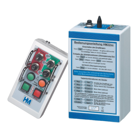
- Page 1 Installation- and Operation Instruction for the Remote Control System HM22XX V32 0108 HM-Funktechnik GmbH, Zum Handenberg 3, 66620 Primstal Tel. 06875 9105 0, Fax. 06875 9105 10 Before operation, read carefully this installation and instruction manual!
- Page 2 This instruction describes the installation and the operation of the following HM-Funktechnik remote control systems: H M 2225 professional remote control system for single drum winches on forest skidders, including: Release, pull, controlled brake release (deadman or intermittent function), gear switch-over of the winch (optionally),...
-
Page 3: Table Of Contents
1.2 Mounting of the receiver............4 2 Operation..................5 2.1 General information ...............5 2.2 Functionality ................6 2.2.1 Button Functionality HM2225...........6 2.2.2 Button Combinations HM 2225 ........6 2.2.3 Button Functionality HM2226...........7 2.2.4 Button Combinations HM 2226 ........7 2.2.5 Button Functionality HM2235...........8 2.2.6 Button Combinations HM 2235 ........8 2.2.7 Button Functionality HM2236...........9... -
Page 4: Installation
1 Installation 1.1 General information All remote control receivers for forestry winches are equipped with a standard 7 pin or 13 pin plug. In general, if the make and model of the winch was specified with the order, the plug will be correctly configured for the customer. However we strictly recommend that the wiring between the winch and the plug is checked, to ensure that it is correct. -
Page 5: Operation
2 Operation 2.1 General information The remote control series HM22xx conforms to the highest standards of safety (Details are available in section 4.1 of this manual). The unit performs a self test every time it is switched on and the internal status is permantly monitored. As a safety feature, if the unit detects an error, it turns itself off. -
Page 6: Functionality
When the receiver is in the active mode, switches to standby mode Stop (see section 4.2) Red LED will extinguish, green LED will light. 2.2.2 Button Combinations HM 2225 Button Combination Combination Functionality Hold Gas+ and Switches the receiver unit from standby mode to active mode, press Stop enabling the control output voltage. -
Page 7: Button Functionality Hm2226
2.2.3 Button Functionality HM2226 Button Button Functionality The winch pulls in cable Ziehen I (only winch 1) Controlled brake release winch 1 K.Lösen I (see DIL switch pos. section 4.6) Brake is released Lösen I (only winch 1) The accelerator actuator pushes Gas+ out the compression pump lever (see DIL switch pos. -
Page 8: Button Functionality Hm2235
2.2.5 Button Functionality HM2235 Button Button Functionality Ziehen I Push lever up Ziehen II winch 1 or winch 2 pulls in cable K.Lösen I Controlled brake release K.Lösen II (see DIL switch pos. section 4.6) Lösen I Pull lever down Lösen II brake 1 or brake 2 is released The accelerator actuator pushes... -
Page 9: Button Functionality Hm2236
2.2.7 Button Functionality HM2236 Button Button Functionality Ziehen I Push lever up, winch 1 or 2 Ziehen II pulls in cable K.Lösen I Controlled brake release K.Lösen II (see DIL switch pos. section 4.6) Lösen I Pull lever down, brake 1 or Lösen II brake 2 is released The accelerator actuator pushes out... -
Page 10: Safety Instructions
The operation of the HM22xx radio remote control systems was designed to eliminate the adverse of dangerous effect of interference or malfunction. HM-Funktechnik, however, strictly recommends that if a user has any problems with a unit it should be taken out of operation. It should then be checked by a skilled and experienced electronic engineer, or sent to the service agent. -
Page 11: Automatic Alarm Function
4.1.4 Automatic alarm function This function will only be active if the DIL switch no. 3 is set to enable it (see section 4.6). If the receiver is on, and the operator does not press a button on the transmitter for six minutes, the receiver switches into alarm mode and initiates a prealarm warning via the vehicle horn. -
Page 12: Relay Functionality
4.5 Relay functionality Relay Relay functionality For future use Self test relay: On start up this relay is latched by pressing the button on the front panel of the receiver unit. If the self test routine of the microprocessor detects a malfunction at any time this relay will be reset, completely isolating the unit from the vehicle power supply. -
Page 13: Dil Switch Functions
4.6 DIL switch functions DIL-switch Functionality Adjusts in combination with DIL 7 and 8 the functionality of the release locking function DIL 7 DIL 8 DIL 1 = ON DIL 1 = OFF Function doesn´t lock Function is locked after 0,5 sec permanently Function is locked after Function is locked after... -
Page 14: The Transmitter Unit
5 The transmitter unit In the hand-held remote control unit, apart from the radio transmitter module, there is an encoder, which formats the control data for transmission, and a battery charge management unit, which permanently monitors the state of the internal battery. 5.1 Charging the hand held transmitter unit There is a 4.8V NiMH battery permanently installed in the transmitter. -
Page 15: Data Format
For further information please contact our service department or your dealer. The HM- Funktechnik service department is available via phone no. +49 (0)6875 9105 17 If you send units for repair to HM-Funktechnik, please send it to the following address: HM-Funktechnik GmbH... -
Page 16: Marking Of Individual Units
7 Marking of individual units The radio remote controllers from the HM22xx series are labelled as follows: e.g. Serial no.: 801011234/36 Year of production, 2005 Week of production Counting number 1234 internal 16-bit HEX-Code Exact model of the unit, e.g. HM2236 Frequency: 434,075 MHz informs you about the exact channel of the unit. -
Page 17: View On The Pc Board Of The Receiver
9 View on the pc board of the receiver... -
Page 18: Block Diagram Of The Receiver
10 Block diagram of the receiver... -
Page 19: Connector Assignment And Dil-Switch Settings
Connector assignment and DIL-switch settings for winch type: ___________________________ Connecting lead – type of plug: ________ Add. connecting lead – type of plug: ____ Add. connecting lead – type of plug: ____ Contact Function Cable-No. Contact Function Cable-No. Contact Function Cable-No.
Need help?
Do you have a question about the HM 2225 and is the answer not in the manual?
Questions and answers