Table of Contents
Advertisement
CONTENTS
1.
2.
3.
4.
5.
...............................................................................................
..........................................................................................
6.
7.
2
......................................................................................
..............................................................................
...........................................................................
....................................................................................
...................................................................................
...........................................................................
.....................................................................................
.........................................................................................
......................................................................................
...........................................................................
........................................................................................
......................................................................
....................................................................
...........................................................................
...........................................................................
..................................................................
............................................................
...............................................
.......................................................
................................................
.................................................
..................................................
.............................................................
..........................................................
.....................
......................
.....................................
....................................
.........................
. 4
. 7
. 8
. 9
. 11
. 11
. 11
. 12
. 13
. 14
. 14
. 15
. 15
. 16
. 16
. 19
. 19
. 20
. 21
. 23
. 24
. 25
. 26
. 27
. 27
. 27
. 30
. 32
. 32
. 34
. 36
Advertisement
Table of Contents

Related Manuals for Honda EXT12D


Summary of Contents for Honda EXT12D
-
Page 1: Table Of Contents
CONTENTS SAFETY INSTRUCTIONS ..............SAFETY LABEL LOCATIONS ............CE mark and noise label locations ..........COMPONENT IDENTIFICATION ............CONTROLS ..................11 Engine Switch ................11 Pilot Lamp (Equipped type only) ..........11 Circuit Protector ................12 Automatic Throttle Switch (Equipped type only) ..... - Page 2 Battery service ................44 Fuse replacement ................ . 46 TRANSPORTING/STORAGE ............47 TROUBLESHOOTING ............... 49 SPECIFICATIONS ................50 REMOTE CONTROL KIT ..............52 WIRING DIAGRAM ................57 MAJOR Honda DISTRIBUTOR ADDRESSES ........ . 61...
- Page 3 The illustrations in this manual are based on F type. Honda Motor Co., Ltd. reserves the right to make changes at any time without notice and without incurring any obligation. No part of this publication may be reproduced without written permission.
-
Page 4: Safety Instructions
SAFETY INSTRUCTIONS To ensure safe operation − Honda generator is designed to give safe and dependable service if operated according to instructions. Read and understand the Owner’s Manual before operating the generator. Failure to do so could result in personal injury or equipment damage. - Page 5 To ensure safe operation − Diesel fuel is extremely flammable a n d e x p l o s i v e u n d e r c e r t a i n conditions. Refuel in a well ventilated area with the engine stopped.
- Page 6 To ensure safe operation − Always make a pre-operation inspection (page ) before you start the engine. You may prevent an accident or equipment damage. Place the generator at least 1 m (3 ft) away from buildings or other equipment during operation. Operate the generator on a level surface.
-
Page 7: Safety Label Locations
These labels warn you of potential hazards that can cause serious injury. Read the labels and safety notes and precautions described in this manual carefully. If a label comes off or becomes hard to read, contact your Honda dealer for a replacement. FUEL CAUTION READ OWNER’S MANUAL... -
Page 8: Ce Mark And Noise Label Locations
CE mark and noise label locations NOISE LABEL CE MARK Manufacturer and address Performance class IP code Maximum ambient Maximum Dry weight temperature altitude [Example: EXT12D CE MARK]... -
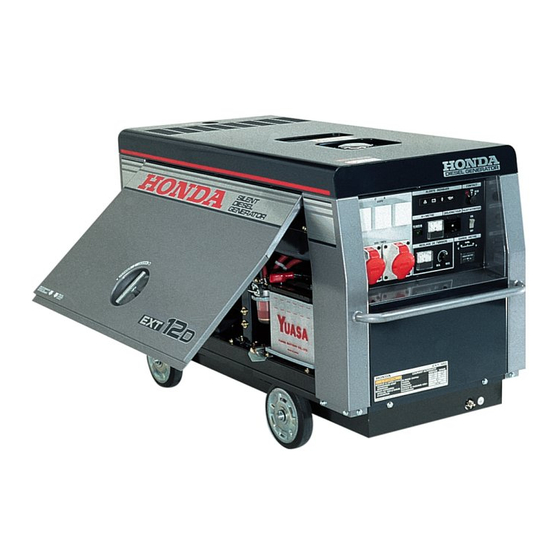
Page 9: Component Identification
COMPONENT IDENTIFICATION COOLING AIR OUTLET EXHAUST OUTLET LIFTING HOOK FUEL FILLER CAP WHEEL (Optional part) GROUND TERMINAL MAINTENANCE LID OPENING KNOB AIR CLEANER MAINTENANCE LID ENGINE OIL FILLER CAP FUSE BOX FUEL VALVE COOLANT RESERVE TANK BATTERY OIL LEVEL GAUGE COOLANT DRAIN BOLT ENGINE OIL DRAIN PLUG FRAME SERIAL NUMBER... - Page 10 EXT12D (F, G and GW Types) PILOT LAMP WARNING LAMPS AC RECEPTACLES AMMETER (SINGLE PHASE) CIRCUIT PROTECTOR ENGINE SWITCH AC RECEPTACLES AUTOMATIC (THREE PHASE) THROTTLE SWITCH FUEL METER HOUR METER VOLT METER VOLTAGE ADUSTMENT KNOB EX10D (B Type) WARNING LAMPS...
-
Page 11: Controls
CONTROLS Engine Switch To start and stop the generator engine. Key position: OFF: To stop the engine. Key can be removed/inserted. To run the engine after starting. START: To start the engine. The starter motor rotates. Detach your hand from the key when the engine is started. The engine switch will automatically return to ON position. -
Page 12: Circuit Protector
Circuit Protector The protector will automatically switch OFF if abnormality or overload is detected in the circuit during operation. Check for abnormality or overload in the equipment before turning the circuit protector ON again. F, G and GW types CIRCUIT PROTECTOR B type CIRCUIT PROTECTOR... -
Page 13: Automatic Throttle Switch (Equipped Type Only)
Automatic Throttle Switch (Equipped type only) Decrease the engine speed automatically without load, and increase the engine speed with output load. Economizes fuel consumption. (F, G and GW types only) When using the lefthand receptacle, the automatic throttle does not function. Turn the automatic throttle switch OFF. -
Page 14: Voltmeter (Equipped Type Only)
Voltmeter (Equipped type only) Indicates the generated AC voltage of the generator. Turn the automatic throttle switch OFF for checking the voltage. (F, G and GW types only) The voltmeter indicates only three-phase voltage. INDICATED VOLTAGE: B type: 230 V F, G and GW types: 400 V VOLTMETER... -
Page 15: Ammeter (Equipped Type Only)
Ammeter (Equipped type only) Indicates loaded current. (F, G and GW types only) The ammeter indicates only three phase loaded current. AMMETER Fuel Meter Indicates the amount of fuel in the fuel tank when the engine switch Refill the fuel tank when the LED starts lighting near the ‘‘E (EMPTY)’’ mark. -
Page 16: Hour Meter
Check the engine oil level, and add recommended oil if level is low (see page See your authorized Honda dealer if the oil pressure warning lamp comes on even though the engine oil is sufficient. To restart the engine, set the engine switch to OFF once and start according to the starting procedure. - Page 17 Turn off the AC circuit breaker OFF. Restart the engine. Check the generator voltage at the voltmeter. If the voltage is correct, check the appliance for good condition. If the voltage is incorrect, see your authorized Honda dealer. GENERAL WARNING LAMP...
- Page 18 The warning lamp lights and engine will stop when the following occurs during operation: − Faulty battery charging system. − No fuel − Engine trouble See your authorized Honda dealer if the warning lamp lights even though the fuel is sufficient. CHARGE WARNING LAMP...
-
Page 19: Pre-Operation Checks
PRE-OPERATION CHECKS Check the generator on a firm, level surface with the engine stopped. Be sure to block the wheel with the two wheel stoppers provided. Maintenance Lid Opening and Closing To open Remove the flange bolt from the bottom of the maintenance lid. Align the maintenance lid knob OPEN and pull up the lid. -
Page 20: Engine Oil
Engine Oil Engine oil is a major factor affecting engine performance and service life. Be sure to check the engine on a level surface with the engine stopped. SAE 10W-30 diesel oil certified to meet or US automobile manufacturer’s requirements for API Service Classification CC or CD (Diesel oils intended for Service CC or CD will show this designation on the container). -
Page 21: Fuel
Fuel Fuel tank capacity: 38 (10.0 US gal , 8.4 Imp gal) Turn the engine switch ON and check the fuel meter. The fuel meter will stop indicating if you leave the engine switch to ON for more than 15 seconds. Turn the engine switch to OFF once and then turn the switch to ON and check the fuel meter. - Page 22 According to season and ambient temperature, a different grade of diesel fuel should be used. The fuel might freeze and prevent the engine from starting if summer fuel is used in winter. If winter fuel is used in summer, it could result in a lack of power. Be sure to use the proper grade of diesel fuel which complies with the ambient temperature.
-
Page 23: Coolant
Coolant Open the maintenance lid (see page Check the coolant level in the reserve tank when the engine is at normal operating temperature. If the level is near the MIN mark, add coolant to bring up to MAX mark. RESERVE TANK MAX (UPPER LEVEL) MIN (LOWER LEVEL) If there is no coolant in the reserve tank, the cooling system should... -
Page 24: Fuel Filter
Coolant Recommendation Use high quality ethylene glycol antifreeze that is specifically formulated for use in aluminum engines. Mix the antifreeze with low- mineral drinking water or distilled water. A 50/50 mixture of ethylene glycol antifreeze and water is recommended for most temperature and provides good corrosion protection. -
Page 25: Battery
Battery The electrolyte level must be kept between the UPPER and LOWER level marks. If the electrolyte level is near the LOWER mark, remove the battery filler caps and carefully add distilled water to the upper level line (see page UPPER LEVEL LOWER LEVEL Batteries produce explosive gases. -
Page 26: Warning Lamps
Turn the engine switch to ON position and check to see whether the warning lamps come on. Return the engine switch to OFF position after the check. If the warning lamp(s) does not come on, consult an authorized Honda dealer. WARNING LAMPS... -
Page 27: Starting And Stopping The Engine
STARTING AND STOPPING THE ENGINE Break-in (initial 50 hours) An initial break-in period will result in longer engine life. Do not run at high speed during break-in. Starting the engine Before starting the engine disconnect any load from the AC receptacle. Open the maintenance lid (see page ) and turn the fuel vale to ON. - Page 28 Turn the automatic throttle switch ON (Equipped type only). AUTOMATIC THROTTLE SWITCH Insert the engine switch key and turn the engine switch to ON position and wait until the charge warning lamp goes off (for about 4 seconds). Turn the engine switch to the START position and hold it there until the engine starts.
- Page 29 After the engine starts, let the engine switch return to the ON position. The pilot lamp comes on after the engine starts (Equipped type only). Warm up the engine for 2 or 3 minutes. Warm-up stabilizes engine rotation and eliminates voltage fluctuation, warm up the engine oil and lubricates relevant parts, reduces abrasion, and prevents seizure.
-
Page 30: Stopping The Engine
Stopping the engine In an emergency: Turn the engine switch OFF. ENGINE SWITCH In normal use: Turn off the electrical appliance’s switch. Turn off the AC circuit protector. AC CIRCUIT PROTECTOR AC CIRCUIT PROTECTOR B type F, G and GW types... - Page 31 Turn off the engine switch. ENGINE SWITCH Open the maintenance lid and turn the fuel valve to OFF. FUEL VALVE...
-
Page 32: Generator Use
GENERATOR USE Connections to a Building’s Electrical System If the generator will be used as an alternative to utility company power, an isolation switch must be installed to disconnect the utility lines from the building when the generator is connected. Installation must be performed by a qualified electrician and must comply with all applicable laws and electrical codes. - Page 33 Limit operation requiring maximum power (see page ) to 30 minutes. For continuous operation, do not exceed the rated power (see page In either case, the total wattage of all appliances connected must be considered. Most appliance motors require more than their rated wattage for startup.
-
Page 34: Ac Applications
AC Applications Make sure all appliances are in good working order before connecting them to the generator. If an appliance begins to operate abnormally, becomes sluggish, or stops suddenly, turn it off immediately. Disconnect the appliance, and determine whether the problem is due to an appliance problem, or generator overloading. - Page 35 Switch on the AC circuit protector. CIRCUIT PROTECTOR F, G and GW types CIRCUIT PROTECTOR B type Plug in the appliance.
-
Page 36: How To Use The Receptacle
When two or more receptacle are used, refer to the table below and apply the load to each receptacle equally to prevent overloading. Voltage fluctuation can be prevented by applying the load equally to the single phase receptacles. EXT12D (F, G and GW types) Receptacle Three phase Single phase... - Page 37 EX10D Receptacle 230 V 115 V Case 32 A 16 A 32 A 16 A × Using 230 V 7.4 kVA Max. 3.7 kVA Max. Total 10 kVA Using 115 V 3.7 kVA 1.8 kVA Max. MAX. at one Total 7.4 kVA Using both 230 V Total 2.5 kVA Total 7.4 kVA...
-
Page 38: Maintenance
If the engine must be run for any reason, be sure the area is well-ventilated. To avoid serious burns, let the engine cool before performing maintenance. Use only genuine Honda parts or their equivalent for maintenance and repair. Parts of lower quality may damage the engine. -
Page 39: Maintenance Schedule
Service more frequently when used in dusty areas. These items should be serviced by your servicing dealer, unless you have the proper tools and are mechanically proficient. Refer to Honda shop manual for service procedures. For commercial use, log hours of operation to determine proper maintenance intervals. -
Page 40: Engine Oil Change
Engine oil change Drain the oil while the engine is still warm to assure rapid and complete draining. Open the maintenance lid (see page Remove the oil filler cap and oil drain plug to drain the oil. Install the drain plug and tighten it securely. Refill with the diesel oil (see page ) and check the oil level. -
Page 41: Air Cleaner Service
Air cleaner service If you operate the generator in very dusty areas, check and replace the air cleaner more often than specified in the MAINTENANCE SCHEDULE. Operating the engine without the air cleaner will cause rapid engine wear. Open the maintenance lid (see page Unhook the clips and remove the air cleaner cover and inner cover. - Page 42 Install the element, inner cover and air cleaner cover in the reverse order of removal. Install the cover with the UP mark facing up and align the tabs of the inner cover and air cleaner cover with cutout of the air cleaner case. Fasten the cover clips securely.
-
Page 43: Fuel Filter Service
Fuel filter service Diesel fuel is extremely flammable and explosive under certain condition. Do not smoke or allow flames or sparks in the area. Open the maintenance lid (see page Turn the fuel valve to OFF position. Loosen the ring nut and then remove the strainer cup, spring and element. -
Page 44: Battery Service
If rapid loss of electrolyte is experienced, or if your battery seems to be weak, causing slow starting or other electrical problems, see your authorized Honda dealer. Open the maintenance cover and check the electrolyte level in each battery cell. Fill the battery with distilled water to the upper level line. - Page 45 Battery cleaning If the battery terminals are contaminated or corroded, remove the battery and clean the terminals. Remove battery set plate. Disconnect the battery cable at the battery negative ( ) terminal, − then at the battery positive ( ) terminal. +...
-
Page 46: Fuse Replacement
To replace the sub fuse pull the old fuse out of the clips with your finger. Push a new fuse into the clips. If the main fuse is blown out, see your authorized Honda dealer. MAIN FUSE SUB FUSE... -
Page 47: Transporting/Storage
TRANSPORTING/STORAGE The engine becomes very hot during operation and remains hot for a while after stopping. Allow the engine to cool before transporting or storing indoors. Transporting When transporting the generator, turn the engine switch OFF and keep the generator level to prevent fuel spillage. Fuel vapor or spilled fuel may ignite. - Page 48 Cover the generator and place it in a well ventilated and dry area. If the generator is still hot, wait until it cools down cover. Remove the radiator cap and check the coolant level before operating the generator after storage. If the coolant level is low see your authorized Honda dealer.
-
Page 49: Troubleshooting
Turn the AC protector ON? circuit protector Check the Take the electrical NO DEFECTS generator to an appliance or authorized equipment for Honda dealer. any defects. Replace the electrical appliance or equipment. DEFECTS Take the electrical appliance or equipment to an electrical shop for repair. -
Page 50: Specifications
SPECIFICATIONS Dimensions and Weight Model EXT12D EX10D Description code Length 1,390 mm (54.7 in) Width 630 mm (24.8 in) Height 815 mm (32.1 in) Dry weight 355 kg (783 lbs) Engine Model GD1100 Type 4-stroke, overhead valve, 3 cylinder diesel Displacement 1,061 cm (64.7 cu-in) - Page 51 Noise Model EXT12D EX10D Type F, G, GW Sound pressure level (Lp ) 79 dB According to 98/37/EC Microphone point CONTROL PANEL Center 1.60 m 1.0 m Guaranteed sound power level 93 dB ) Tested by 2000/14/EC Specifications are subject to change without notice.
-
Page 52: Remote Control Kit
REMOTE CONTROL KIT Remote Control Kit (Installation) Remove the cap from the 7 pin connector on the generator cover, and connect the 7 pin connector of the remote control switch box cable there. 7 PIN CONNECTOR GENERATOR SIDE Be sure to install the cap on the connector when the remote control kit is not used. - Page 53 Starting the engine Before starting the engine disconnect any load from the AC receptacle. Be sure that the fuel valve lever is at the ON auto throttle switch (equipped type only) is at the ON, and the generator engine switch is at the OFF position respectively.
- Page 54 Turn the remote control switch on the generator cover to ON. REMOTE CONTROL SWITCH Be sure to turn the remote control switch to OFF when the starting motor is operated by the engine switch on the generator control panel with the remote control kit installed.
- Page 55 Turn the engine switch on the remote control switch box to ON. Turn the engine switch to ON position and wait until the glow lamp of starter button (with glow lamp) goes off (for about 4 seconds). ENGINE SWITCH STARTER BUTTON (with glow lamp) Push the start button and hold until the engine starts.
- Page 56 If the warning lamp lights and engine stops: Turn off the AC circuit protector OFF. Check the fuel level. If the fuel is at the proper level, bring your generator to an authorized Honda dealer to have it checked. STARTER BUTTON PILOT LAMP Stopping the engine To stop the engine in an emergency, turn the engine switch OFF.
-
Page 57: Wiring Diagram
WIRING DIAGRAM ACOR AC Output Receptacle BLACK AC, G AC Generator YELLOW Auto Throttle Unit BLUE ATSw Auto Throttle Switch GREEN Automatic Voltage Regurator WHITE Automatic Throttle BROWN Motor ORANGE Battery LIGHT BLUE Circuit Protector LIGHT GREEN CBxB Control Box block PINK Current Trans GRAY... - Page 58 EXT12D (F, G and GW Types)
- Page 59 EX10D (B Type)
- Page 60 RECEPTACLE Shape Type F, G, GW...
-
Page 61: Major Honda Distributor Addresses
MAJOR Honda DISTRIBUTOR ADDRESSES IN EUROPE NAME OF FIRM (COMPANY) ADDRESS TEL: FAX: Honda (U.K.) Limited 470 London Road, Slough, Tel: 01753-590-590 Berkshire, SL38QY, Fax: 01753-590-000 United Kingdom Honda Europe Power Equipment S.A. Pole 45 Rue des Chataigniers Tel: 2-38-65-06-00... - Page 62 NAME OF FIRM (COMPANY) ADDRESS TEL: FAX: OY Brandt AB Tuupakantie 4 Tel: 90-895-501 SF-01740, Vantaa Fax: 90-878-5276 Finland TIMA PRODUCTS A/S Tårnfalkevej 16, Postboks 511 Tel: 31-49-17-00 DK 2650 Hvidovre Fax: 36-77-16-30 Denmark Greens Polig. Industrial Congost Tel: 93-871-84-50 08530, La Garriga Fax: 93-871-81-80 (Barcelona), Spain...
- Page 63 GENERATOR EXT12D/EX10D OWNER'S MANUAL MANUEL DE L'UTILISATEUR BEDIENUNGSANLEITUNG oHonda Motor Co., Ltd. 2002 efgsY1100.2006.04 36ZC6616 MANUAL DE EXPLICACIONES Printed in Japan 00X36-ZC6-6160...
Need help?
Do you have a question about the EXT12D and is the answer not in the manual?
Questions and answers