Table of Contents
Advertisement
Quick Links
SERVICE
Mono Laser MFP
Refer to the service manual in the GSPN (see the rear cover) for more information.
Mono Laser MFP
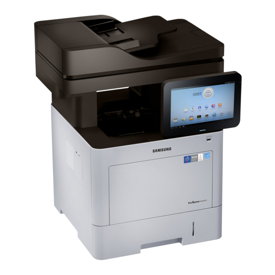
ProXpress M458 series
SL-M4580FX, SL-M4583FX
(Ver 1.02)
MANUAL
1. Precautions
2. Product Specifications and Description
3. Disassembly and Reassembly
4. Troubleshooting
5. System Diagram
6. Reference Information
Contents
Advertisement
Table of Contents
Troubleshooting


Need help?
Do you have a question about the SL-M4580FX and is the answer not in the manual?
Questions and answers