Table of Contents
Advertisement
Quick Links
Advertisement
Table of Contents

Subscribe to Our Youtube Channel
Related Manuals for RCF AX 8042


Summary of Contents for RCF AX 8042
- Page 1 USER MANUAL AX 8042 - AUTOMIXER WITH 8 AUDIO INPUTS AND 6 AUDIO OUTPUTS...
-
Page 3: Table Of Contents
DESCRIPTION AUDIO INPUT BLOCK DIAGRAM AUDIO OUTPUT BLOCK DIAGRAM FRONT PANEL REAR PANEL HOW TO LINK TWO AX 8042 EACH OTHER NOTES ABOUT THE RDNET SOFTWARE RDNET 2 SOFTWARE INSTALLATION START THE RDNET SOFTWARE (REL. 2.0.96.3363) VIA USB MAIN WINDOW... -
Page 4: Safety Precautions
The manual is to be considered an integral part of this product and must accompany it when it changes ownership as a reference for correct installation and use as well as for the safety precautions. RCF S.p.A. will not assume any responsibility for the incorrect installation and / or use of this product. WARNING WARNING: To prevent the risk of fire or electric shock, never expose this product to rain or humidity (indoor use only). - Page 5 RCF etc.), which must guarantee the security of the system / installation over time, also considering, for example, the mechanical vibrations normally generated by loudspeakers. To prevent the risk of falling equipment, do not stack multiple units of this product unless this possibility is specified in the user manual.
-
Page 6: Installation
Each AX 8042 can work as a dual-room combiner with 2 independent ‘automix’ settings. AX 8042 has 10 logic inputs (GPIN), 4 logic outputs (GPOUT) plus 2 (RL1, RL2) with a relay. All logic inputs and outputs have removable screw terminals and are fully configurable. -
Page 7: Audio Input Block Diagram
- 4 programmable logic outputs (GPOUT) plus 2 with relay (RL1, RL2). - Dual-room combiner with 2 independent ‘automix’ settings. - 16-input 8-output matrix (plus 4 additional outputs) by linking together two AX 8042. - Configurable ALC (‘Automatic Level Control’) when a noise detection microphone is connected to the input no.8 . -
Page 8: Audio Output Block Diagram
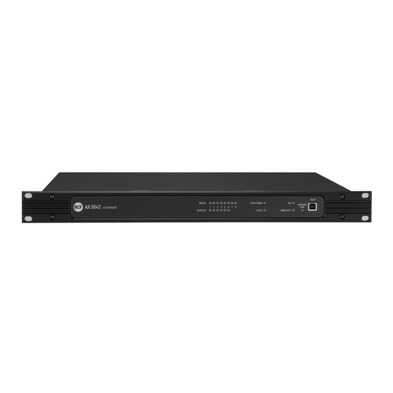
AUDIO OUTPUT BLOCK DIAGRAM FRONT PANEL INPUTS LEDs: each LED indicates the signal presence (green) / peak (red) at its respective audio input. OUTPUTS LEDs: each LED indicates the signal presence (green) / peak (red) at its respective audio output. CTRL/COMM LED: it blinks when receiving control data. -
Page 9: Rear Panel
GPI/O LED: when lit, it indicates the activation of at least a logic input / output. ON LED: when lit, it indicates the AX 8042 automixer is properly powered and operating. ERR/FAULT LED: when lit, it indicates a fault or data transmission / reception errors. - Page 10 EXTENSION LINK IN: input to link the EXTENSION LINK OUT of the second AX 8042 (optional). Read the manual section 'How to link two AX 8042 each other'. EXTENSION LINK OUT: output to link the EXTENSION LINK IN of the second AX 8042 (optional).
-
Page 11: How To Link Two Ax 8042 Each Other
Input for the power cord (to be connected to mains through an earthed socket only). HOW TO LINK TWO AX 8042 EACH OTHER Two AX 8042 can be linked each other to get a 16-input 8-output matrix EXTENSION LINK (plus 4 additional outputs) through the EXTENSION LINK ports (RJ 45 sockets) on their rear panels. -
Page 12: Rdnet 2 Software Installation
RDNET 2 SOFTWARE INSTALLATION Minimum requirement: a PC with Microsoft 'Windows® XP', 'Vista' or '7' operating system, having an available USB port. The operating system shall also have the drivers for the emulation of the serial RS 232 interface via the USB port. Before installing a new software release, it is necessary to remove the previous version (if installed). -
Page 13: Start The Rdnet Software (Rel. 2.0.96.3363) Via Usb
Link (through a suitable cable) the computer USB port to the one of the AX 8042 automixer (labelled HOST Run the RDNET software (in Windows, click): Start > Programs > RCF > RDNet > RDNet (or double-click RDNet icon on the desktop). In the main menu, click ‘Advanced’ and then ‘Com Setup..’... -
Page 14: Main Window
(in the bottom bar) the word ‘OFFLINE’ becomes ‘ONLINE’. The AX 8042 module now appears. Point the PC mouse at the AX 8042 module and double-click (or right-click and select ‘Show Obj Details’) to open the automixer setting window. -
Page 15: Preset Manager
Select either MASTER if the AX 8042 currently linked to the PC is the MASTER unit (or the only one) or SLAVE if the AX 8042 currently linked to the PC is the SLAVE unit. Important: when two AX 8042 are linked each other (MASTER and SLAVE), this settings shall be carried out (in two stages) on both units, by linking the USB cable to the first unit, then to the second unit. -
Page 16: Input Channel Settings
INPUT CHANNEL SETTINGS INPUT CHANNEL SETTING Each audio input has a level bar , from –60 to 0 dB. 0 dB is the peak level before distortion. All input controls are here listed: EDIT opens or closes the setting window of the equalizer, the compressor, the automatic gain control (AGC), the noise gate and the digital trimmer. -
Page 17: Equalizer
LINE: changes the input sensitivity from LINE (for signals coming from other mixers, CD / MP3 players, etc.) to MIC (microphones that are not pre-amplified). After clicking LINE, choose ‘Yes’ on the confirmation request. Click MIC to turn back to LINE. EQUALIZER EQUALIZER Click EDIT to open the EQ setting window (of its respective audio input). - Page 18 PHASE PLOT: if selected, the phase plot is shown (green line). Devices commands: STORE: it sends and stores the equalization to AX 8042. SEND: it sends (without storing) the equalization to AX 8042. For each filter, frequency and gain can be adjusted either graphically (through the mouse) by dragging the little coloured square or in an analytical way (by inserting the values in the cells or rotating the control).
-
Page 19: Compressor
To add a second filter (i.e. PEQ): enable the filter 2, select the PEQ filter type, its gain and central frequency, then set its Q factor. Finally, click either STORE (send and store) or SEND (send without storing) to send all EQ settings to AX 8042. COMPRESSOR COMPRESSOR The compressor does not modify a signal having a level lower than the predetermined threshold and compresses a signal with higher level. -
Page 20: Automatic Gain Control ( Agc )
USE EXAMPLE: 1. Set THRESHOLD to a level lower than 0 dB (e.g. –15 dB). 2. Set RATIO (i.e. 4:1). 3. Adjust OUT GAIN in order to increase the signal output gain (to minimize the compressor attenuation, i.e. +10 dB). AUTOMATIC GAIN CONTROL (AGC) AUTOMATIC GAIN CONTROL (AGC) The automatic gain control does not modify a signal having a level lower than the... -
Page 21: Noise Gate
USE EXAMPLE: 1. Set THRESHOLD to a level lower than 0 dB (e.g. –45 dB). 2. Adjust the TARGET fader to fix the optimal average level of the signal (e.g. –30 dB). 3. Set RATIO (e.g. 2:1). NOISE GATE NOISE GATE The noise gate automatically reduces an audio input level when its signal is below the defined threshold (or absent). -
Page 22: Digital Trimmer
DIGITAL TRIMMER DIGITAL TRIMMER The digital trimmer adjusts the audio input sensitivity. It can help optimize a too low or too high audio signal. To access the digital trimmer (of a single input), click EDIT on the respective channel and select the INPUT DSP window. -
Page 23: Automatic Level Control (Alc)
EXAMPLE (SEE THE ‘EXAMPLE’ FIGURE) EXAMPLE The first zone button (A ZONE) of all BM 3003 paging microphones is assigned to the MASTER A output only. The second zone button (B ZONE) of all BM 3003 paging microphones is assigned to the MASTER B output only. -
Page 24: Automixer
AUTOMIXER AUTOMIXER Click AUTOMIX SETUP in the main window. AM1 ON: toggles the automixer no.1 (keep it on if used). AM2 ON: toggles the automixer no.2 (keep it on if used). MAX NOM1: sets the maximum number of open channels simultaneously (assigned to the automixer no.1 and with NOM 1 activated). -
Page 25: Audio Outputs And Slave Unit Controls
AUDIO OUTPUTS AND SLAVE UNIT CONTROLS The 6 audio outputs (A-F) of the MASTER unit (single or first AX 8042) are on the right of the software main window. slave ax 8042, all controls of the audio outputs of the... -
Page 26: Audio Output Settings
AUDIO OUTPUT SETTINGS AUDIO OUTPUT SETTINGS Each audio output has a level bar , from –60 to 0 dB. 0 dB is the peak level before distortion. All audio output controls are now listed. EDIT opens or closes the setting window of both the equalizer and the limiter. toggles the parametric equalizer. -
Page 27: Equalizer
EQUALIZER EQUALIZER Click EDIT to open the EQ/LIMITER setting window (of the respective audio output). It is possible to set up to 5 independent filters (Filter 1, 2, 3, 4, 5). Enabled: click the checkbox to toggle each filter. Move the mouse on its white background (making it green) to highlight a filter (if present) on the EQ graph. - Page 28 PHASE PLOT: if selected, the phase plot is shown (green line). Devices commands: STORE: it sends and stores the equalization to AX 8042. SEND: it sends (without storing) the equalization to AX 8042. For each filter, frequency and gain can be adjusted either graphically (through the mouse) by dragging the little coloured square or in an analytical way (by inserting the values in the cells or rotating the control).
-
Page 29: Limiter
LIMITER LIMITER The limiter does not modify a signal having a level lower than the predetermined threshold and limits a signal with higher level. A limiter is in fact a compressor having a high compression ratio. It can be really useful to avoid signal distortion due to too high levels. THRESHOLD: adjusts the level above which the limiter compresses the signal. -
Page 30: Mixer Matrix
MIXER MATRIX Click MATRIX (in the software main window) to access the audio matrix window to match the 8 MASTER inputs (plus the 8 SLAVE inputs, if available) and the first 4 MASTER outputs (A-D buses) or the first 4 SLAVE outputs (A-D buses, if available). Each of the 2 additional outputs (E, F) can be assigned to one of the A-D buses. -
Page 31: Matrix Nodes
MATRIX NODES MATRIX NODES For each bus, every audio input has the following controls: ON: toggles the audio input in the correspondent bus. It is the main switch of the node. A-MIX1: assigns the node to the control of the automixer no.1, which automatically adjusts the audio input level according to the number of open channels. -
Page 32: Groups
GPI logic input) that refers to a group simultaneously acts on all audio inputs and outputs assigned to that group. For each AX 8042 (MASTER or SLAVE), it is possible to set up to 16 CONTROL groups and 16 MUTE groups. -
Page 33: Control Group
CONTROL GROUP CONTROL GROUP CTRL GROUP (n): group name that can be edited after a double-click on the text. EDIT: opens the window of audio input / output selection. The green light beside (when lit) means that at least one input / output has been selected (if the light is off, the group has not been configured yet). -
Page 34: Force On/Off
FORCE ON/OFF This function allows to either increase (FORCE ON) or reduce (FORCE OFF) an input level forcedly. Its activation can be either automatic (when the audio input signal level is above the noise gate threshold) or through an external command linked to a logic input (GPIN). Click FORCE ON/OFF in the main window. -
Page 35: Gpi/Gpo Section ( Logic Inputs And Outputs , Master Unit Only )
GPI/GPO (LOGIC INPUTS AND OUTPUTS, MASTER UNIT ONLY) For the MASTER AX 8042 only, it is possible to set up to 10 logic inputs (GPIN), 4 logic outputs (GPOUT) plus 2 (RL1, RL2) with relay. Click GPI/GPO in the main window. -
Page 36: Logic Input Functions
LOGIC INPUT FUNCTIONS LOGIC INPUT FUNCTIONS NONE: disabled. LOAD PRESET: load the selected preset. MUTE INPUT: mutes the selected audio input. MUTE OUTPUT: mutes the selected audio output. MUTE GROUP: mutes the selected group. MUTE ALL: mutes all audio outputs. ENABLE IN: forces the opening of the selected audio input channel (when muted). -
Page 37: Logic Output Functions
Each logic output includes the following parameters: Function: selection of the function assigned to the logic output (read the next paragraph). ChannelID: depending on the selected function, select the number corresponding to a preset, an audio input / output or a group. Normally Open GPOUT 1-4: the logic output is normally high (5 V) and will switch to low (0) when activated. -
Page 38: Remote Controls Section ( Master Unit Only )
REMOTE CONTROLS (MASTER UNIT ONLY) This manual section concerns the software configuration of RCF TS 9918 remote controls. Refer to the TS 9918 / TS 9918-W user manual about all that concerns remote control installation, hardware settings and use. It is possible to configure up to four TS 9918 remote controls for the MASTER unit only. -
Page 39: Generic Settings
GENERIC SETTINGS GENERIC SETTINGS Mode: operating mode selection among static, dynamic, combined. Before selecting the combined mode, first it is necessary to set the remote control in both static and dynamic modes. Enable: toggles the remote control (keep it on when using). STATIC MODE SETTINGS STATIC MODE SETTINGS Click one of the 8 T1-T8 buttons to configure it. -
Page 40: Ac Rdnet In/Out Plug Board Installation
AC RDNET IN/OUT PLUG BOARD INSTALLATION The AC RDNET IN/OUT PLUG optional board allows the AX 8042 automixer control via RDNET. Refer to the RDNET CONTROL 8 manual about the complete RDNET software use and further information. 1. Unplug the power cord. -
Page 41: Internal Jumper Settings
INTERNAL JMP1 (for RL1 logic output) AND JMP2 JUMPER SETTINGS IMPORTANT: internal jumper settings shall be carried out only by either RCF or an authorised service centre. As default, the RL1 logic output with relay is assigned to the device fault indication. -
Page 42: Specifications
SPECIFICATIONS AUDIO PERFORMANCE DATA A/D – D/A converters: 24 bits Sampling rate: 48 kHz Max. audio input level: +24 dBu (balanced) Max. MIC input gain: +50 dB Max. audio output level: +24 dBu Output impedance: 50 Ω Frequency response: 20 Hz ÷ 20 kHz (±0.5 dB) Dynamic range: >... -
Page 43: Rs 485 Serial Port Protocol
- A command is terminated by a CR (0x0D ASCII character). - AX 8042 / ZX 8060 always replies to a command with a response line, terminated by a CR. The first field is the response code, if it applies, further fields will follow separated by spaces. - Page 44 <MODEL_ID> is an integer from 1 to 32 MODEL (e.g. 1: ‘AX 8042 Automixer’, 2: ‘ZX 8060 Zoner’, 3 to 2: reserved for future use). <TEXT> is an optional field and may include a description (a text with max. 40 characters) of the unit delimited by characters “...
- Page 48 Except possible errors and omissions. RCF S.p.A. reserves the right to make modifications without prior notice. HEADQUARTERS: RCF S.p.A. Italy tel. +39 0522 274 411 e-mail: info@rcf.it RCF UK tel. 0844 745 1234 Int. +44 870 626 3142 e-mail: info@rcfaudio.co.uk RCF France tel.
Need help?
Do you have a question about the AX 8042 and is the answer not in the manual?
Questions and answers