Table of Contents
Advertisement
Advertisement
Table of Contents
Troubleshooting

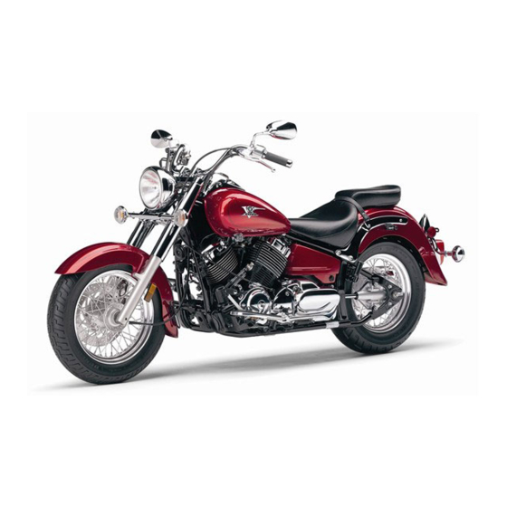
Related Manuals for Yamaha 2007 V Star XVS650AX


Summary of Contents for Yamaha 2007 V Star XVS650AX
- Page 1 OWNER’S MANUAL XVS650X XVS650AX 3B7-28199-22...
- Page 3 Welcome to the Yamaha world of motorcycling! As the owner of the XVS650X/XVS650AX, you are benefiting from Yamaha’s vast experience and newest technology re- garding the design and manufacture of high-quality products, which have earned Yamaha a reputation for dependability.
-
Page 4: Important Manual Information
This manual should be considered a permanent part of this motorcycle and should remain with it even if the motorcycle is subsequently sold. Yamaha continually seeks advancements in product design and quality. Therefore, while this manual contains the most current product information available at the time of printing, there may be minor discrepancies between your motorcycle and this manual. - Page 5 IMPORTANT MANUAL INFORMATION EAU10200 XVS650X/XVS650AX OWNER’S MANUAL ©2007 by Yamaha Motor Co., Ltd. 1st edition, March 2007 All rights reserved. Any reprinting or unauthorized use without the written permission of Yamaha Motor Co., Ltd. is expressly prohibited. Printed in Japan.
-
Page 6: Table Of Contents
TABLE OF CONTENTS SAFETY INFORMATION ....1-1 Adjusting the shock Adjusting the engine Location of important labels ....1-5 absorber assembly ....3-15 idling speed ......6-14 Luggage strap holders ....3-16 Checking the throttle cable DESCRIPTION ........2-1 Sidestand ........3-16 free play ........6-15 Left view ..........2-1 Ignition circuit cut-off system .. - Page 7 TABLE OF CONTENTS Lubricating the swingarm pivots .........6-26 Checking the front fork ....6-26 Checking the steering ....6-27 Checking the wheel bearings ..6-27 Battery ..........6-28 Replacing the fuses ......6-29 Replacing the headlight bulb ..6-30 Replacing a turn signal light bulb or the tail/brake light bulb ..6-31 Replacing the auxiliary light bulb (XVS650AX).......6-32 Supporting the motorcycle ....6-33...
-
Page 8: Safety Information
SAFETY INFORMATION EAU10251 AND/OR WHEN MADE NECES- • Ride where other motorists can SARY BY MECHANICAL CONDI- see you. Avoid riding in another MOTORCYCLES SINGLE TIONS. motorist’s blind spot. TRACK VEHICLES. THEIR SAFE USE Many motorcycle accidents in- AND OPERATION ARE DEPENDENT Safe riding volve inexperienced operators. - Page 9 Modifications made to this motorcycle other motorists can see you. the single most critical factor in the pre- not approved by Yamaha, or the re- The posture of the operator and vention or reduction of head injuries. moval of original equipment, may ren- passenger is important for proper Always wear an approved helmet.
- Page 10 Maximum load: been specifically designed for use on create instability due to improper XVS650AX 200 kg (441 lb) this motorcycle. Since Yamaha cannot weight distribution or aerody- XVS650X 180 kg (397 lb) test all other accessories that may be namic changes. If accessories...
- Page 11 SAFETY INFORMATION tor and may limit control ability, Always turn the engine off before eyes, see your doctor immediately. therefore, such accessories are leaving the motorcycle unattended If any gasoline spills on your skin not recommended. and remove the key from the main or clothing, immediately wash the Use caution when adding electri- switch.
-
Page 12: Location Of Important Labels
SAFETY INFORMATION EAU10381 Location of important labels Please read the following important labels carefully before operating this vehicle. - Page 13 SAFETY INFORMATION 3 XVS650X 3 XVS650AX 5FB-21668-01...
-
Page 14: Description
DESCRIPTION EAU10410 Left view 1. Shift pedal (page 3-7) 2. Fuel cock (page 3-10) 3. Starter (choke) knob (page 3-11) 4. Shock absorber assembly spring preload adjusting ring (page 3-15) 5. Helmet holder (page 3-14) 6. Storage compartment (page 3-14) 7. -
Page 15: Right View
DESCRIPTION EAU10420 Right view 1. Engine oil filter element (page 6-8) 2. Battery (page 6-28) 3. Fuses (page 6-29) 4. Main switch/steering lock (page 3-2) 5. Air filter element (page 6-12) 6. Brake pedal (page 3-8) -
Page 16: Controls And Instruments
DESCRIPTION EAU10430 Controls and instruments 1. Clutch lever (page 3-7) 2. Left handlebar switches (page 3-6) 3. Speedometer unit (page 3-5) 4. Fuel tank cap (page 3-9) 5. Right handlebar switches (page 3-6) 6. Throttle grip (page 6-15) 7. Brake lever (page 3-8) -
Page 17: Instrument And Control Functions
Do not expose any key to exces- a Yamaha dealer to have them re-reg- sively high temperatures. istered. Do not use the key with the red Do not place any key close to bow for driving. -
Page 18: Main Switch/Steering Lock (Xvs650X)
INSTRUMENT AND CONTROL FUNCTIONS Keep other immobilizer system EAU10460 EAU10471 Main switch/steering lock Main switch/steering lock keys away from the main switch (XVS650X) (XVS650AX) as they may cause signal inter- ference. The main switch/steering lock controls The main switch/steering lock controls the ignition and lighting systems, and is the ignition and lighting systems, and is used to lock the steering. - Page 19 INSTRUMENT AND CONTROL FUNCTIONS EAU10480 EAU10680 To unlock the steering ON (XVS650X) LOCK All electrical systems are supplied with The steering is locked, and all electrical power, and the headlight, meter lighting systems are off. The key can be re- and taillight come on, and the engine moved.
-
Page 20: Indicator And Warning Lights
”. when an electrical circuit monitoring the ECA11020 engine is defective. When this occurs, CAUTION: have a Yamaha dealer check the self- Do not use the parking position for diagnosis system. 1. High beam indicator light “ ” an extended length of time, other- 2. -
Page 21: Speedometer Unit
If the immobilizer system is de- key and both standard keys to a 1. Tripmeter reset knob fective, the indicator light will start flash- Yamaha dealer and have the stan- 2. Speedometer ing a pattern when the key is turned to dard keys re-registered. -
Page 22: Handlebar Switches
INSTRUMENT AND CONTROL FUNCTIONS EAU12347 Right (XVS650AX) position. To cancel the turn signal Handlebar switches lights, push the switch in after it has re- turned to the center position. Left EAU12500 Horn switch “ ” Press this switch to sound the horn. EAU12660 Engine stop switch “... -
Page 23: Clutch Lever
INSTRUMENT AND CONTROL FUNCTIONS EAU12733 EAU12820 EAU12870 Hazard switch “ ” (XVS650AX) Clutch lever Shift pedal (XVS650X) With the key in the “ON” or “ ” posi- tion, use this switch to turn on the haz- ard lights (simultaneous flashing of all turn signal lights). -
Page 24: Shift Pedal (Xvs650Ax)
INSTRUMENT AND CONTROL FUNCTIONS EAU12880 EAU12890 EAU12941 Shift pedal (XVS650AX) Brake lever Brake pedal XVS650X 1. Shift pedal 1. Brake lever 1. Brake pedal The shift pedal is located on the left The brake lever is located at the right side of the engine and is used in com- handlebar grip. -
Page 25: Fuel Tank Cap
INSTRUMENT AND CONTROL FUNCTIONS EAU13120 2. Turn the key counterclockwise to EAU13211 Fuel tank cap Fuel the original position, remove it, and then close the lock cover. NOTE: The fuel tank cap cannot be installed unless the key is in the lock. In addition, the key cannot be removed if the cap is not properly installed and locked. -
Page 26: Fuel Cock
Always turn the fuel as well as to the exhaust system. cock lever to this position when the en- Your Yamaha engine has been de- gine is not running. signed to use regular unleaded gaso- line with a research octane number of 91 or higher. -
Page 27: Starter (Choke) Knob
INSTRUMENT AND CONTROL FUNCTIONS This indicates reserve. With the fuel EAU13620 Starter (choke) knob “ ” cock lever in this position, the fuel re- serve is made available. Turn the fuel cock lever to this position if you run out of fuel while riding. -
Page 28: Seats (Xvs650X)
INSTRUMENT AND CONTROL FUNCTIONS EAU14184 To install the rider seat Tightening torque: Seats (XVS650X) 1. Insert the projection on the front of Passenger seat nut: the rider seat into the seat holder 13 Nm (1.3 m·kgf, 9.4 ft·lbf) Passenger seat as shown, and then place the seat in the original position. -
Page 29: Seats (Xvs650Ax)
INSTRUMENT AND CONTROL FUNCTIONS EAU14191 Tightening torque: Seats (XVS650AX) Passenger seat nut: 13 Nm (1.3 m·kgf, 9.4 ft·lbf) Passenger seat To remove the passenger seat Remove the nut and washer, and then pull the passenger seat up. 1. Bolt To install the rider seat 1. -
Page 30: Helmet Holder
INSTRUMENT AND CONTROL FUNCTIONS 2. Install the passenger seat. EAU14281 EAU14481 Helmet holder Storage compartment NOTE: The storage compartment is located on Make sure that the seats are properly the left side of the vehicle. secured before riding. To open the storage compartment 1. -
Page 31: Adjusting The Shock Absorber Assembly
INSTRUMENT AND CONTROL FUNCTIONS EAU14860 2. To increase the spring preload and Adjusting the shock absorber thereby harden the suspension, assembly turn the adjusting ring in direction (a). To decrease the spring pre- load and thereby soften the sus- pension, turn the adjusting ring in direction (b). -
Page 32: Luggage Strap Holders
Yamaha’s ignition circuit cut-off Always have a Yamaha dealer system has been designed to assist service the shock absorber. the operator in fulfilling the respon- sibility of raising the sidestand be- fore starting off. -
Page 33: Ignition Circuit Cut-Off System
INSTRUMENT AND CONTROL FUNCTIONS below and have a Yamaha dealer re- EAU15312 Ignition circuit cut-off system pair it if it does not function proper- The ignition circuit cut-off system (com- prising the sidestand switch, clutch switch and neutral switch) has the fol- lowing functions. - Page 34 5. Push the start switch. Does the engine start? The neutral switch may be defective. The motorcycle should not be ridden until checked by a Yamaha dealer. With the engine still running: 6. Move the sidestand up. 7. Keep the clutch lever pulled.
-
Page 35: Pre-Operation Checks
PRE-OPERATION CHECKS EAU15593 The condition of a vehicle is the owner’s responsibility. Vital components can start to deteriorate quickly and unexpectedly, even if the vehicle remains unused (for example, as a result of exposure to the elements). Any damage, fluid leakage or loss of tire air pressure could have serious consequences. -
Page 36: Pre-Operation Check List
• Make sure that operation is smooth. • Check cable free play. Throttle grip 6-15, 6-24 • If necessary, have Yamaha dealer adjust cable free play and lubricate cable and grip housing. • Make sure that operation is smooth. Control cables 6-23 •... - Page 37 Chassis fasteners — • Tighten if necessary. Instruments, lights, signals • Check operation. — and switches • Correct if necessary. • Check operation of ignition circuit cut-off system. Sidestand switch 3-16 • If system is defective, have Yamaha dealer check vehicle.
-
Page 38: Operation And Important Riding Points
Become thoroughly familiar system to enable starting, one of the Yamaha dealer check the electrical cir- with all operating controls and following conditions must be met: cuit. their functions before riding. The transmission is in the neutral Consult a Yamaha dealer re- position. -
Page 39: Starting A Warm Engine
OPERATION AND IMPORTANT RIDING POINTS then go off, have a Yamaha deal- 7. When the engine is warm, turn the EAU16640 Starting a warm engine er check the electrical circuit. If starter (choke) off. Follow the same procedure as for start-... -
Page 40: Shifting
OPERATION AND IMPORTANT RIDING POINTS EAU16671 Shifting gears lets you control the and drive train, which are not Shifting amount of engine power available for designed withstand starting off, accelerating, climbing hills, shock of forced shifting. XVS650X etc. The gear positions are shown in the il- lustration. -
Page 41: Tips For Reducing Fuel Consumption
Turn the engine off instead of let- immediately have a Yamaha dealer result in engine overheating must be ting it idle for an extended length of check the vehicle. -
Page 42: Parking
OPERATION AND IMPORTANT RIDING POINTS EAU17170 Parking When parking, stop the engine, remove the key from the main switch, and then turn the fuel cock lever to “OFF”. EWA10310 WARNING Since the engine and exhaust system can become very hot, park in a place where pedestri- ans or children are not likely to touch them. -
Page 43: Periodic Maintenance And Minor Repair
Yamaha dealer certain maintenance work correctly. do it for you. NOTE: If you do not have the tools or experi- ence required for a particular job, have a Yamaha dealer perform it for you. -
Page 44: Periodic Maintenance And Lubrication Chart
The annual checks must be performed every year, except if a kilometer-based maintenance is performed in- stead. From 50000 km, repeat the maintenance intervals starting from 10000 km. Items marked with an asterisk should be performed by a Yamaha dealer as they require special tools, data and technical skills. ODOMETER READING (× 1000 km) - Page 45 PERIODIC MAINTENANCE AND MINOR REPAIR ODOMETER READING (× 1000 km) ANNUAL ITEM CHECK OR MAINTENANCE JOB CHECK √ √ √ √ √ • Check for cracks or damage. 9 * Brake hose • Replace. Every 4 years • Check runout, spoke tightness and for damage. √...
- Page 46 PERIODIC MAINTENANCE AND MINOR REPAIR ODOMETER READING (× 1000 km) ANNUAL ITEM CHECK OR MAINTENANCE JOB CHECK • Check starter (choke) operation. √ √ √ √ √ √ 24 * Carburetors • Adjust engine idling speed and synchronization. • Change. √...
- Page 47 PERIODIC MAINTENANCE AND MINOR REPAIR • Replace the brake hoses every four years and if cracked or damaged.
-
Page 48: Removing And Installing Panels
PERIODIC MAINTENANCE AND MINOR REPAIR EAU18771 XVS650AX XVS650X Removing and installing pan- The panels shown need to be removed to perform some of the maintenance jobs described in this chapter. Refer to this section each time a panel needs to be removed and installed. -
Page 49: Checking The Spark Plugs
Do not attempt to 1. Spark plug cap diagnose such problems yourself. In- 2. Remove the spark plug as shown, stead, have a Yamaha dealer check with the spark plug wrench includ- the vehicle. ed in the owner’s tool kit. -
Page 50: Engine Oil And Oil Filter Element
PERIODIC MAINTENANCE AND MINOR REPAIR 3. Check each spark plug for elec- 2. Clean the surface of the spark plug EAU19743 Engine oil and oil filter ele- trode erosion and excessive car- gasket and its mating surface, and ment bon or other deposits, and replace then wipe off any grime from the The engine oil level should be checked it if necessary. - Page 51 PERIODIC MAINTENANCE AND MINOR REPAIR 2. Place an oil pan under the engine NOTE: NOTE: to collect the used oil. The engine oil should be between the Skip steps 4–7 if the oil filter element is 3. Remove the engine oil filler cap minimum and maximum level marks.
- Page 52 PERIODIC MAINTENANCE AND MINOR REPAIR 7. Install the oil filter element covers Recommended engine oil: by installing the bolts, and then See page 8-1. tighten them to the specified Oil quantity: Without oil filter element replace- torque. ment: 2.60 L (2.75 US qt) (2.29 Imp.qt) Tightening torque: With oil filter element replacement: Oil filter element cover bolt:...
-
Page 53: Final Gear Oil
If any mediately turn the engine off and NOTE: leakage is found, have a Yamaha deal- check for the cause. The oil level should be at the brim of the er check and repair the vehicle. In addi- 11. -
Page 54: Cleaning The Air Filter Element
PERIODIC MAINTENANCE AND MINOR REPAIR 2. Remove the oil filler bolt and drain 6. Check the final gear case for oil EAU33381 Cleaning the air filter element bolt to drain the oil from the final leakage. If oil is leaking, check for The air filter element should be cleaned gear case. - Page 55 PERIODIC MAINTENANCE AND MINOR REPAIR ECA10480 NOTE: CAUTION: If dust or water collects in the air filter Make sure that the air filter ele- check hose, remove the clamp from it, ment is properly seated in the and then remove the plug to drain the air filter case.
-
Page 56: Adjusting The Carburetors
Therefore, most carbu- checked and, if necessary, adjusted as retor adjustments should be left to a follows at the intervals specified in the Yamaha dealer, who has the neces- periodic maintenance and lubrication sary professional knowledge and expe- chart. -
Page 57: Checking The Throttle Cable Free Play
Yamaha dealer at the intervals specified in the periodic Tire air pressure maintenance and lubrication chart. The tire air pressure should be checked and, if necessary, adjusted before each ride. - Page 58 XVS650AX 200 kg (441 lb) in it, or if the sidewall is cracked, con- XVS650X 180 kg (397 lb) tact a Yamaha dealer immediately and * Total weight of rider, passenger, car- go and accessories have the tire replaced.
-
Page 59: Spoke Wheels
If any dam- begins to show crosswise lines, proved this model age is found, have a Yamaha Yamaha Motor Co., Ltd. have a Yamaha dealer replace dealer replace the wheel. Do not the tire immediately. attempt even the smallest repair to... -
Page 60: Adjusting The Clutch Lever Free Play
PERIODIC MAINTENANCE AND MINOR REPAIR EAU22041 2. To increase the clutch lever free 5. To increase the clutch lever free Adjusting the clutch lever free play, turn the adjusting bolt in di- play, turn the adjusting nut in direc- play rection (a). -
Page 61: Adjusting The Brake Lever Free Play
PERIODIC MAINTENANCE AND MINOR REPAIR EAU22092 system. If there is air in the hy- Adjusting the brake lever free draulic system, have a Yamaha play dealer bleed the system before operating the motorcycle. Air in the hydraulic system will dimin-... -
Page 62: Adjusting The Brake Pedal Position And Free Play
PERIODIC MAINTENANCE AND MINOR REPAIR EAU22231 EWA10670 Adjusting the brake pedal po- WARNING sition and free play It is advisable to have a Yamaha dealer make these adjustments. XVS650X NOTE: The brake pedal position should be ad- justed before adjusting the brake pedal free play. -
Page 63: Adjusting The Rear Brake Light Switch
PERIODIC MAINTENANCE AND MINOR REPAIR To increase the brake pedal free play, EAU22270 EAU22380 Adjusting the rear brake light Checking the front brake pads turn the adjusting nut at the brake rod in switch and rear brake shoes direction (a). To decrease the brake The front brake pads and the rear brake pedal free play, turn the adjusting nut in shoes must be checked for wear at the... -
Page 64: Checking The Front Brake Fluid Level
Observe these precautions: the wear limit line, have a Yamaha As the brake pads wear, it is nor- dealer replace the brake shoes as a mal for the brake fluid level to grad- set. -
Page 65: Changing The Brake Fluid
EAU22720 EAU23100 Changing the brake fluid Checking and lubricating the denly, have a Yamaha dealer Have a Yamaha dealer change the cables check the cause. brake fluid at the intervals specified in The operation of all control cables and the NOTE after the periodic mainte- the condition of the cables should be nance and lubrication chart. -
Page 66: Checking And Lubricating The Throttle Grip And Cable
PERIODIC MAINTENANCE AND MINOR REPAIR EAU23111 EAU44270 Recommended lubricant: Checking and lubricating the Checking and lubricating the Lithium-soap-based grease (all-pur- throttle grip and cable brake and shift pedals pose grease) The operation of the throttle grip should be checked before each ride. In addi- tion, the cable should be lubricated at the intervals specified in the periodic maintenance chart. -
Page 67: Checking And Lubricating The Brake And Clutch Levers
EWA10730 WARNING If the sidestand does not move up and down smoothly, have a Yamaha dealer check or repair it. Recommended lubricant: The operation of the brake and clutch Lithium-soap-based grease (all-pur- levers should be checked before each... -
Page 68: Lubricating The Swingarm Pivots
If any damage is found or the front Check the inner tubes for scratches, fork does not operate smoothly, damage and excessive oil leakage. have a Yamaha dealer check or re- pair it. To check the operation 1. Place the vehicle on a level sur- face and hold it in an upright posi- tion. -
Page 69: Checking The Steering
2. Hold the lower ends of the front fork legs and try to move them for- ward and backward. If any free play can be felt, have a Yamaha dealer check or repair the steering. 6-27... -
Page 70: Battery
To charge the battery burns. Avoid any contact with Have a Yamaha dealer charge the bat- skin, eyes or clothing and al- tery as soon as possible if it seems to ways shield your eyes when have discharged. -
Page 71: Replacing The Fuses
(MF) battery charg- 2. Main fuse 4. Carburetor heater fuse 3. Spare main fuse er, have a Yamaha dealer 5. Parking lighting fuse (for XVS650AX only) 6. Backup fuse (for odometer and immobilizer charge your battery. The main fuse and the fuse box, which... -
Page 72: Replacing The Headlight Bulb
3. Turn the key to “ON” and turn on the electrical circuit in question to check if the device operates. 1. Headlight bulb holder 4. If the fuse immediately blows again, have a Yamaha dealer check the electrical system. 6-30... -
Page 73: Replacing A Turn Signal Light Bulb Or The Tail/Brake Light Bulb
1. Screw oil, otherwise the transparency of 7. Have a Yamaha dealer adjust the the glass, the luminosity of the bulb, XVS650X headlight beam if necessary. and the bulb life will be adversely af- fected. -
Page 74: Replacing The Auxiliary Light Bulb (Xvs650Ax)
PERIODIC MAINTENANCE AND MINOR REPAIR XVS650AX EAU33411 Replacing the auxiliary light bulb (XVS650AX) If the auxiliary light bulb burns out, re- place it as follows. 1. Remove the headlight unit by re- moving the screws. 1. Auxiliary light bulb socket 1. -
Page 75: Supporting The Motorcycle
EWA10820 wheel or performing other maintenance WARNING requiring the motorcycle to stand up- It is advisable to have a Yamaha right. Check that the motorcycle is in a dealer service the wheel. stable and level position before starting Securely support the motor- any maintenance. - Page 76 PERIODIC MAINTENANCE AND MINOR REPAIR 2. Lift the wheel up between the fork Tightening torque: legs. Wheel axle: 59 Nm (5.9 m·kgf, 43 ft·lbf) NOTE: Make sure that there is enough space 6. Tighten the front wheel axle pinch between the brake pads before insert- bolt to the specified torque.
-
Page 77: Rear Wheel
EAU25141 shaft lever. To remove the rear wheel EWA10820 WARNING It is advisable to have a Yamaha dealer service the wheel. Securely support the motor- cycle so that there is no danger 1. Bolt of it falling over. -
Page 78: Troubleshooting
(See page 6-20.) self. However, should your motorcycle EWA10660 require any repair, take it to a Yamaha WARNING dealer, whose skilled technicians have After adjusting the brake pedal free the necessary tools, experience, and... -
Page 79: Troubleshooting Chart
Remove the spark plugs and check the electrodes. The engine does not start. Have a Yamaha dealer check the vehicle. Check the battery. 4. Battery The engine turns over The battery is good. -
Page 80: Motorcycle Care And Storage
Rust and corrosion can develop matte colored finished parts. Be ECA10771 even if high-quality components are sure to consult a Yamaha dealer for CAUTION: advice on what products to use be- used. A rusty exhaust pipe may go un- Avoid using strong acidic wheel fore cleaning the vehicle. - Page 81 MOTORCYCLE CARE AND STORAGE cleaning products, solvent or After normal use ECA10790 CAUTION: thinner, fuel (gasoline), rust re- Remove dirt with warm water, a mild movers or inhibitors, brake flu- detergent, and a soft, clean sponge, Do not use warm water since it in- id, antifreeze or electrolyte.
-
Page 82: Storage
7. Let the motorcycle dry completely Always store your motorcycle in a cool, NOTE: before storing or covering it. dry place and, if necessary, protect it Consult a Yamaha dealer for advice on EWA11130 against dust with a porous cover. WARNING what products to use. - Page 83 MOTORCYCLE CARE AND STORAGE 3. Drain the carburetor float cham- EWA10950 °C (90 °F)]. For more information WARNING bers by loosening the drain bolts; on storing the battery, see page this will prevent fuel deposits from To prevent damage or injury from 6-28.
-
Page 84: Specifications
SPECIFICATIONS Dimensions: Compression ratio: Air filter: 9.00 :1 Overall length: Air filter element: Starting system: XVS650AX 2450 mm (96.5 in) Dry element Electric starter XVS650X 2340 mm (92.1 in) Fuel: Lubrication system: Overall width: Recommended fuel: Wet sump XVS650AX 930 mm (36.6 in) Unleaded gasoline only Engine oil: XVS650X 880 mm (34.6 in) - Page 85 SPECIFICATIONS Transmission type: Rear tire: Rear: Constant mesh 5-speed 250 kPa (36 psi) (2.50 kgf/cm²) Type: Operation: Front wheel: With tube Left foot operation Size: Wheel type: Gear ratio: 170/80-15M/C 77S Spoke wheel 1st: Manufacturer/model: Rim size: 38/14 (2.714) XVS650AX DUNLOP/D404G XVS650AX 16M/C x MT3.00 2nd: XVS650X BRIDGESTONE/EXEDRA...
- Page 86 SPECIFICATIONS Rear suspension: Neutral indicator light: 12 V, 1.7 W × 1 Type: High beam indicator light: Swingarm (monocross) 12 V, 1.7 W × 1 Spring/shock absorber type: Turn signal indicator light: Coil spring/gas-oil damper 12 V, 1.7 W × 1 Wheel travel: Engine trouble warning light: XVS650AX 98.0 mm (3.86 in)
-
Page 87: Consumer Information
Yamaha EAU26400 Vehicle identification number dealer or for reference in case the vehi- cle is stolen. -
Page 88: Motorcycle Noise Regulation (For Australia)
1. Model label The model label is affixed to the frame under the rider seat. (See page 3-12.) Record the information on this label in the space provided. This information will be needed when ordering spare parts from a Yamaha dealer. - Page 89 INDEX Noise regulation (for Australia) ....9-2 Air filter element, cleaning ....6-12 Final gear oil..........6-11 Auxiliary light bulb, Front fork, checking.......6-26 Panels, removing and installing ....6-6 replacing (XVS650AX) ....... 6-32 Fuel ............3-9 Parking............ 5-5 Fuel cock..........3-10 Part locations .......... 2-1 Fuel consumption, tips for reducing ..5-4 Pass switch..........
- Page 90 INDEX Throttle cable free play, checking ..6-15 Throttle grip and cable, checking and lubricating ..... 6-24 Tires ............6-15 Tool kit ............ 6-1 Troubleshooting ........6-36 Troubleshooting chart ......6-37 Turn signal indicator light ......3-4 Turn signal light bulb or tail/ brake light bulb, replacing....
- Page 92 YAMAHA MOTOR CO., LTD. PRINTED ON RECYCLED PAPER PRINTED IN JAPAN 2007.05-0.3×1 CR...
Need help?
Do you have a question about the 2007 V Star XVS650AX and is the answer not in the manual?
Questions and answers
Yamaha v star 650 classic 2007