Table of Contents
Advertisement
Quick Links
Installation & Service Instructions
About the Boiler
About Safety
See inside cover for models covered by these instructions.
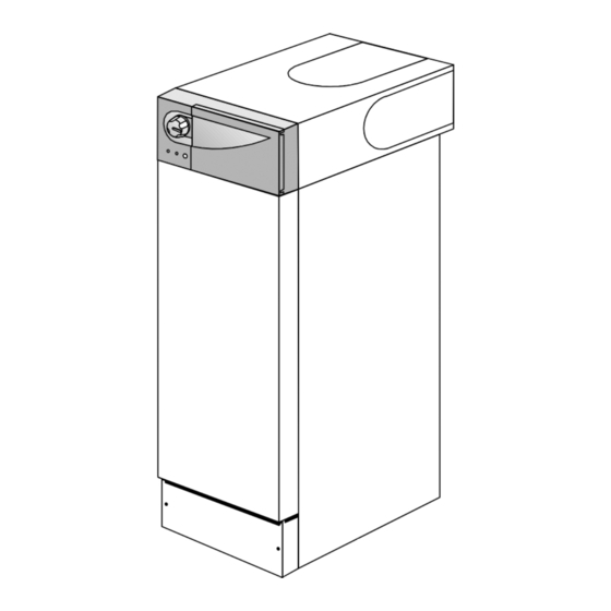
This Floor Mounted Fan Assisted Gas Boiler is available as Conventional or Balanced Flue.
This boiler is for use with Natural Gas (G20) only at 20mbar and for use in GB & IE.
The Gas Safety (Installation and Use) Regulations 1998.
'' In your own interest, and that of safety, it is law that all gas appliances are installed by competent
persons, in accordance with the above regulations. Failure to install appliances correctly could
lead to prosecution.''
Installation must be in accordance with the Installation & Service Instructions and the rules in
force.
Leave these instructions and the Benchmark Log Book with the user for use on future calls.
Kingfisher Mf
RSL40 - 100, CFL40 -100
The code of practice for the installation,
commissioning & servicing of central heating systems
TM
Advertisement
Table of Contents

Subscribe to Our Youtube Channel
Related Manuals for Potterton Kingfisher Mf CFL40 - 100


Summary of Contents for Potterton Kingfisher Mf CFL40 - 100
- Page 1 Installation & Service Instructions Kingfisher Mf RSL40 - 100, CFL40 -100 About the Boiler See inside cover for models covered by these instructions. This Floor Mounted Fan Assisted Gas Boiler is available as Conventional or Balanced Flue. This boiler is for use with Natural Gas (G20) only at 20mbar and for use in GB & IE. About Safety The Gas Safety (Installation and Use) Regulations 1998.
-
Page 2: Table Of Contents
7. Short List of Spares.........36 8. Flue Kits & Optional Extras.......38 Fig. 1 Potterton is a member of the Benchmark initiative and SAFETY, PERFORMANCE & QUALITY fully supports the aims of the programme. Benchmark Kingfisher Mf boilers have been assessed by a... -
Page 3: Technical Data
Technical Data Boiler models Heat Input & Efficiency figures are quoted as gross Maximum Rate Output 11.72 14.65 17.58 20.52 23.45 26.38 29.31 Btu/h 40,000 50,000 60,000 70,000 80,000 90,000 100,000 Input 14.47 18.31 22.00 25.60 28.95 32.98 36.76 Btu/h 49,372 62,474 75,064... - Page 4 CFL Flue Outlet CFL Flue Outlet Shown Shown (Two Centres Available) (127 or 153 Outlet) RSL Flue Outlet Shown 50-100 model shown RSL Flue Outlet Shown 25 Front Clearance 400 recommended for servicing (if non removable) Fig. 2 Technical Data Publication No.
-
Page 5: Introduction
Installation & Service Instructions or otherwise recommended in writing. Any direct connection of a control device not approved by Potterton could invalidate the CE Certification and normal appliance warranty. Introduction... -
Page 6: Installation Requirements
Service publication Part 19 - Building and Kitchen Work). 22mm gas supply pipe should be used up to the inlet If in doubt advice must be sought from Potterton. connection of the gas cock on the boiler. RSL boilers may be installed in any room, although particular... -
Page 7: Air Supply - Cfl/Rsl
The boiler requires the clearances shown in Fig. 2. Conventional Flue Models - See Page 7 & 8. Balanced Flue Models - See Pages 9 & 10. Conventional Flue Models Air Supply The air requirements must meet BS 5440 Part 2. The room in which the boiler is installed must be ventilated. -
Page 8: Flue Systems - Cfl/Rsl
Flue Systems Approved A flue system (lined throughout its length) must be Terminal provided to evacuate the flue products of combustion from the boiler. Reference should be made to the Cement building regulations and BS 5440:1. and the flue Sealing Seal Plate system efficiency should be checked in accordance... - Page 9 Balanced Flue Models Air Supply The air requirements must meet BS 5440 Part 2. The room in which the boiler is installed does not require a purpose provided air vent. If the boiler is installed in a compartment, permanent air vents are required in the compartment, one at high level and one at low level, either direct to the outside air or to a room.
- Page 10 Likely flue positions requiring Fig. 6 a flue terminal guard • Where a horizontal flue is sited less than 2m Terminal Position with Minimum Distance (mm) above a balcony, above ground, or above a flat roof to which people have access, a suitable Fanned Draught Balanced Flue terminal guard must be fitted.
-
Page 11: The System
The System If a three port diverter valve is used as shown in Figs.8 & 9, a by-pass is not necessary since one circuit is always open. Where a pair of two port valves are used, a by-pass If plastic pipe is used for the central heating circuit there is necessary. - Page 12 To size the expansion vessel it is first necessary to Cylinder calculate the volume of water in the system in litres. The The hot water cylinder must be an indirect coil type or a following volumes may be used as a conservative guide to direct cylinder fitted with an immersion calorifier suitable calculating the system volume.
- Page 13 Fig. 7 Fig. 8 Installation Requirements Publication No. 5102977...
- Page 14 Fig. 9 Fig.10 14 Installation Requirements Publication No. 5102977...
-
Page 15: Installation
2. Installation Install the boiler These instructions assume you have decided on where the boiler will be located and the type of flue system to be used. 1. Carefully unpack the boiler. Remove and place aside the tailpipe/gravity stat kit and on CFL boilers, the ancillary bag containing the top and rear blanking plates with seal and control panel. - Page 16 2. Attach the flue to the flue spigot. This product is fitted with a combustion products discharge safety device (TTB) which must not be taken out of operation at any time. The component is fitted to ensure that any blockage or partial blockage of the flue Ceiling Min.
- Page 17 Fitting the Blanking Plate Screw Rear Cut to size Fit Trim 1. If the flue is not fitted in the fully forward Blanking Plate (if required) position, the rear blanking plate will need to to work surface be cut to size, cut trim to length as required. See Fig.
- Page 18 9. Slide the flue back until it engages in the elbow bayonet connection, twist clockwise to lock. 10.Drill through pilot hole and lock flue in position using the self tapping screw provided. 11.Make good the wall around the flue, both inside and outside.
-
Page 19: Connect The Gas Supply
Connect the Gas Supply Disconnect Gas Cock 1. Ensure that the gas supply is isolated. from the 2. Disconnect the gas cock from the gas valve. Stage Gas Valve 3. Connect the gas supply to the gas cock using a suitable adaptor. Connect Gas Pipe Important: Gas Cock... -
Page 20: Connect The Power Supply Cable
Connect the Power Supply Cable 1. Cable clamping is provided on the front of the controls panel. Feed the cables up and over the back of the chassis, through the clamp and into the terminal connection. Note: When connecting the power supply cable, ensure that the length of the earth wire is such, that if the power supply cable pulls out of the cable clamp the live and... -
Page 21: Install The Optional Programmer
feed and vent pipes (close coupling is acceptable) see BS 5449 for further details. a. Re-position the overheat thermostat to Gravity DHW position as explained under 2.4, page 19. b. Switched live from external control circuit to MAINS 'SwL'. c. Fit a link between terminals MAINS 'SwL' and MAINS 'L' d. -
Page 22: Commissioning
The commissioning and boiler adjustment must When checking for gas soundness open only be carried out by a suitably qualified all windows and doors in the room. person. Potterton offer this service on a Extinguish all naked lights, cigarettes, pipes, etc. chargeable basis. 22 Commissioning... -
Page 23: Commission The Boiler
3.1 Commission the Boiler 11 If a programmer is fitted set both DHW & CH to (tick box when done) the 'On' position and check that the room and cylinder thermostats, where fitted are set to Open Vented Systems - Remove the pump high temperatures. -
Page 24: Instruct The User
Mounting Bracket that adequate servicing is carried out at least once a year by a Potterton Service Engineer or Fig. 23 a C.O.R.G.I. Registered Installer. Overheat Thermostat Leave a permanent card attached to the boiler... -
Page 25: Service & Replacement Of Parts
4. Service & Replacement of Parts Read these: To ensure continued efficient operation of the appliance, it is recommended that it is checked and cleaned as necessary at regular intervals. The frequency of servicing will depend upon the particular installation conditions and usage but in general once per year should be adequate. -
Page 26: General Access
General Access Warning: Before attempting to remove any component from the appliance first disconnect the mains electricity supply by removing the plug from the wall socket or by switching off the appliance at the external isolating switch. Notes: The 'O' (stand-by) position on the boiler temperature control will leave parts of the boiler Live. -
Page 27: Electronic Control Board
Electronic Control Board • Gain General Access - See 4.1 For better access of controls tray See 4.1 Note 5. 1. Disconnect all connectors and wires, unscrew the two securing screws and remove the board. 2. On re-assembly refer to the wiring diagram when re-connecting wires and connectors. -
Page 28: Burner, Gas Valve, Injector & Electrode
Burner, Gas Valve, Injector & Electrode • Gain General Access - See 4.1 1. Disconnect the gas cock from the gas valve. 2. Disconnect the wiring from the gas valve. 3. Remove the combustion chamber cover - 2 screws. 4. Remove the gas valve/burner assembly - 2 screws. -
Page 29: Combustion Chamber Insulation
Combustion Chamber Insulation Combustion Chamber Insulation (40 Model) Insulation • Gain General Access - See 4.1 Securing Tabs 1. Remove the burner/gas valve assembly - See 4.6. 2. Remove combustion chamber front cover - 2 screws Note: To avoid release of dust and fibrous material the insulation material should be dampened before removal. -
Page 30: Wiring Diagrams
5. Wiring Diagrams Air Pressure Switch Fig. 29 Functional Wiring Diagram Publication No. 5102977... - Page 31 T.T.B. CFL Models Only Fig. 30 Pictorial Wiring Diagram Publication No. 5102977...
-
Page 32: Fault Finding
6. Fault Finding Guide If Red LED is 'ON' and the Boiler fails to work check the following: Electrical Plugs (PL1 to PL6) are to remain connected to the Circuit Board for Fault Finding checks. ALL Electrical Power to the Heating System OFF - NO External Call for Heat (Thermostat & Programmer OFF) Boiler Temperature Knob Set to'0' (Fully anti-clockwise 'click' OFF) - Gas &... - Page 33 Turn OFF Mains Supply to Heating System & on RSL models check that link plug is fitted & there is continuity. Replace if defective. On CFL models check wiring to T.T.B. Thermostat, check T.T.B. thermostat continuity & replace if defective. Fault Finding Publication No.
- Page 34 34 Fault Finding Publication No. 5102977...
- Page 35 Fault Finding Publication No. 5102977...
-
Page 36: Short List Of Spares
7. Short List Of Spare Parts 50-100 Models Model CON0060D Fig. 31 Short List Spare Parts Publication No. 5102977... - Page 37 Item No. G.C. No. Description Qty. Part No. E02-325 Thermistor 404524 173-130 Overheat Thermostat 404517 E02-367 Main Wiring Harness 242110 E78-236 Gas Valve Assembly CFL/RSL40 - 100 5102729 379-672 Pilot Burner - Honeywell 402559 114-963 'O' Ring 401656 E02-372 Electrode - Honeywell 402561 E02-365 Main PCB...
-
Page 38: Flue Kits & Optional Extras
8. Flue Kits & Optional Extras Concentric Vertical Flue Kit Telescopic Horizontal Flue Kit Pitched Roof Sales Code: SUPKITD Sales Code: 1SUPFLUE Flashing Kit Sales Code: (up to 300mm) Standard A) Terminal Assy. PUMAKITL B) Terminal Clamp Bracket Sales Code: 2SUPFLUE (up to 550mm) Alternative C) Flue Tube Adaptor A) Telescopic Flue assy. - Page 39 Installation instructions included as necessary with each kit. Fig. 33 Flue Kits & Optional Extras Publication No. 5102977...
- Page 40 All goods are sold subject to our standard Conditions of Sale which are available on request. Baxi Potterton Brownedge Road, Bamber Bridge Preston, Lancashire PR5 6SN www.potterton.co.uk...
Need help?
Do you have a question about the Kingfisher Mf CFL40 - 100 and is the answer not in the manual?
Questions and answers