Table of Contents
Advertisement
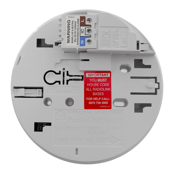
RadioLINK
Alarm Base
Model: Ei168RC
Read and retain carefully for as long as the product is being used. It contains vital information on the operation
and installation. This booklet should be regarded as part of the product.
If you are just installing the Alarm, this booklet must be given to the householder. This booklet is to be given to
any subsequent user.
Instructions
Advertisement
Table of Contents

Subscribe to Our Youtube Channel
Related Manuals for RadioLink Ei168RC


Summary of Contents for RadioLink Ei168RC
- Page 1 RadioLINK Alarm Base Model: Ei168RC Instructions Read and retain carefully for as long as the product is being used. It contains vital information on the operation and installation. This booklet should be regarded as part of the product. If you are just installing the Alarm, this booklet must be given to the householder. This booklet is to be given to...
-
Page 2: Table Of Contents
2. Quick install guide ..................3. Installation ....................4. Troubleshooting the RF link ..............5. Checking & maintaining the alarm system ........6. Technical specification ................7. Guarantee ....................8. Limitations of radio communications ........... 9. Getting the RadioLINK Base serviced ............ -
Page 3: Overview
The primary function of the RadioLINK base is to interconnect all Alarms in the system, i.e. when one Alarm senses fire, the Ei168RC base attached to that Alarm will transmit an RF signal that will activate the sounders in all the other Alarms. - Page 4 RadioLINK interconnect and Remote Control (RC) Model No. - RadioLINK Devices Ei450 Remote Controller Remote Controller for Ei2110, Ei160RC Series, Ei140RC Series when fitted with Ei168RC RadioLINK bases Ei408, Ei428 & Ei428SK Input and output relay modules Ei407 Manual Call Point...
- Page 5 Mixed Wired & RadioLINK System RadioLINK System Hardwired interconnect Wireless interconnect Alarm Controller Alarm Controller In this configuration the alarm controller must be a RadioLINK device. It is not possible to control the system from the hardware interconnect side...
-
Page 6: Quick Install Guide
2. Quick Install Guide The Ei168RC RadioLINK Base must be installed by a qualified electrician. The maximum number of RadioLINK Alarms in each system is 12. Install each RadioLINK Base in the centre of the ceiling at least 0.30m from light fittings as per the Smoke/Heat Alarm instructions and connect to nearest mains circuit. -
Page 7: Installation
BLUE LIGHT systems. It is essential that the RadioLINK Bases are House Coded. Press and hold the Button to test each Alarm. Check that the red light is flashing, the horn is sounding. To ensure the Alarm is communicating with others check that the blue light comes on for approx 3 seconds. - Page 8 3. Installation Mixing the Live and Neutral connections will damage the alarm. Ensure that the same colours are used throughout the premises for Live, Neutral and Interconnect wires (if used). WARNING Mains operated products should be installed by a qualified electrician as per the requirements for Electrical Installations published as IEE Wiring Regulations –...
- Page 9 Orientate all RadioLINK bases in the same direction It is best practice to align all the RadioLINK bases in the same direction as shown in the diagram above. This will ensure that all the antennas are in parallel which will...
- Page 10 Fixing & Wiring Select a location complying with the advice in the Smoke/Heat Alarm instruction leaflet. Disconnect the AC mains supply from the circuit that is going to be used. Remove the cover from the terminal block as shown here. Bring the mains wires through the ceiling and thread them through the hole in the rear of the base.
- Page 11 To prevent air draughts affecting smoke or heat entering the alarm it is important to seal the area around the hole in the ceiling with foam or silicon rubber. Screw the base to the ceiling using a single screw for now. The second screw should be inserted at the end of this procedure to secure the base permanently.
- Page 12 2 hours to charge and test again. Press and hold the test button. The red led will flash and the horn will sound. Repeat this installation procedure for all RadioLINK bases in the system.
- Page 13 A maximum of 12 RadioLink bases may be used in any one system. If your system has more than 12 Alarms please consult your supplier or contact tech support (see back page). House Coding When all the RadioLINK bases have been installed and fitted with Alarms, you are now ready to house code the system.
- Page 14 Check that all the devices have been successfully house coded. This can be done by counting the amount of blue flashes on each RadioLINK base. The number of flashes should correspond to the number of devices in the system. e.g. if the system has 4 Alarms and a remote controller (e.g.
-
Page 15: Troubleshooting The Rf Link
20 seconds on each unit in turn. The red light will flash, the Alarm will sound and blue light on the RadioLINK Base sidewall will illuminate continuously for around 3.5 seconds. All other Alarms should sound (this may take up to 20 seconds). - Page 16 HOUSE CODE SWITCH (factory reset) and house code the system again. To reset each RadioLINK base insert and hold a screwdriver into the house code slot on the base as shown here. The blue light will come on solid.
- Page 17 4. Troubleshooting the RF link If when checking the RadioLINK interconnection some of the alarms do not respond to the button test, then: (i) Ensure you have held the test button down for up to 20 seconds and the blue light has come on continuously for 3.5 seconds.
- Page 18 Section “Installation”. The RadioLINK interconnection should then be checked by counting the number of flashes and button testing all units. Note: The RadioLINK Base will only transmit and repeat alarm RF messages as long as the Smoke Alarm is detecting fire or for 30 minutes whichever is the shorter.
-
Page 19: Checking & Maintaining The Alarm System
5. Checking & Maintaining the Alarm System Check that the green light is on continuously to indicate that mains power is present and that the red light flashes every 40 seconds. Frequent testing of the system is a requirement to ensure its continued and safe operation. Guidelines and best practices for testing are as follows: After the system is installed... - Page 20 To test the RadioLINK system, press and hold the test button on one of the Alarms. The blue light on the side of the Ei168RC base will come on solid for around 3.5 seconds. Continue to hold the test button until all the Alarms in the system are sounding.
- Page 21 10 seconds End of Life (EOL) Check Check the replace unit by date on all Ei168RC bases and attached Alarms. If the date has been exceeded then the device should be replaced.
-
Page 22: Technical Specification
Vacuum all around the smoke entry openings in the smoke Alarms to remove any excess dust, lint, cobwebs, etc. 6. Technical Specification Supply Voltage 230VAC ~50Hz, 80mA Battery Back-up 10 year Rechargeable Lithium RF Frequency 868.499Mhz Temp Range C to 40 C (Cat 3) Humidity 15% - 95% (Non Condensing) -
Page 23: Guarantee
7. Guarantee Ei Electronics guarantees the Model Ei168RC for 5 years from date of purchase against any defects that are due to faulty materials or workmanship. This guarantee only applies to normal conditions of use and service and does not include damage resulting from accident, neglect, misuse, unauthorised dismantling, or contamination howsoever caused. - Page 24 If this device does cause such interference, which can be verified by turning the RadioLINK device on and off (remove both the mains and turn off backup power supplies), the user is encouraged to eliminate the interference by one or more of the following measures: (i) Re-orientate or re-locate the unit.
-
Page 25: Getting The Radiolink Base Serviced
State the nature of the fault, where the RadioLINK Base and Alarm were purchased and the date of purchase. Do not snap the Smoke/Heat Alarm on to the RadioLINK Base as this connects the battery and the unit may beep or Alarm in the post. - Page 26 0889 Hereby, Ei Electronics declares that this Ei168RC RadioLink Alarm Base, is in compliance with the essential requirements and other relevant provisions of Directive 1999/5/EC. The Declaration of Conformity may be...
- Page 28 Aico Ltd Mile End Business Park, Maesbury Road, Oswestry, Shropshire SY10 8NN, U.K. Telephone: 0870 7584000 www.aico.co.uk Ei Electronics Shannon Industrial Estate, Shannon, Co. Clare, Ireland. Telephone: +353 (0)61 471277 www.eielectronics.com © Ei Electronics 2013 P/N B17688 Rev 3...
Need help?
Do you have a question about the Ei168RC and is the answer not in the manual?
Questions and answers
HOW DO YOU OPEN THE COVER