Table of Contents
Advertisement
Available languages
Available languages
I N S T A L L A T I O N I N S T R U C T I O N S
Instructions d´installation
Instrucciones de instalación
Instruções de Instalação
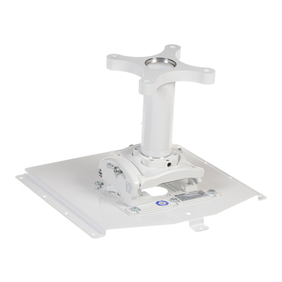
Cinema Projector Mount
RPA Elite Series Projector Mount
RPA Elite Series Projector Mount
RPA Elite Series Projector Mount
RPA Elite Series Projector Mount
RPA Elite Series Projector Mount
CHF4000/4500
Advertisement
Table of Contents

Related Manuals for Epson CHF 4000


Summary of Contents for Epson CHF 4000
- Page 1 I N S T A L L A T I O N I N S T R U C T I O N S Instructions d´installation Instrucciones de instalación Instruções de Instalação Cinema Projector Mount RPA Elite Series Projector Mount RPA Elite Series Projector Mount RPA Elite Series Projector Mount RPA Elite Series Projector Mount...
- Page 2 Installation Instructions CHF4000/4500 LEGEND Adjust Tighten Fastener Ajuster Serrez les fixations Regolare Serrare il fissaggio Einstellen Befestigungsteil festziehen Ajustar Apretar elemento de fijación Afstellen Bevestiging vastdraaien Ajustar Apertar fixador Security Wrench Loosen Fastener Clé de sécurité Desserrez les fixations Chiave di sicurezza Allentare il fissaggio Sicherheitsschlüssel Befestigungsteil lösen...
-
Page 3: Important Safety Instructions
CHF4000/4500 Installation Instructions DISCLAIMER WARNING: Exceeding the weight capacity can result in Milestone AV Technologies and its affiliated corporations and serious personal injury or damage to equipment! It is the subsidiaries (collectively "Milestone"), intend to make this installer’s responsibility to make sure the combined weight of manual accurate and complete. - Page 4 Installation Instructions CHF4000/4500 DIMENSIONS 6.50 1.69 2.25 4.50 1.69 5.50 1.50" DIA NPT 2.75 5.50 YAW ADJUSTMENT POINT 20 5.36 4.61 2.72 ROLL ADJUSTMENT PITCH ADJUSTMENT POINT 3 POINT 20 DIMENSIONS: [MILLIMETERS] INCHES...
- Page 5 CHF4000/4500 Installation Instructions TOOLS REQUIRED FOR INSTALLATION 5/32" - security (included) PARTS A (1) C (1) [Projector mount] B (1) [Interface bracket] [Ceiling pipe] F (1) E (1) G (1) 5/16-18 x 3/8" 5/16-18 x 3/8" 5/32" (security) (security) D (1) [Ceiling plate] J (9) H (9)
-
Page 6: Ceiling Installation
Installation Instructions CHF4000/4500 CEILING INSTALLATION NOTE: Projector mount can be mounted flush against the ceiling without using the ceiling pipe. See Sections 1a, 1b and 1c for flush mounting options. Additional hardware may be required. Threaded Pipe Installation Carefully determine required mounting location. IMPORTANT ! : This will require knowing the lens to screen distance. - Page 7 CHF4000/4500 Installation Instructions Projector Mount Installation to Ceiling Pipe WARNING: IMPROPER INSTALLATION CAN RESULT IN SERIOUS PERSONAL INJURY OR DAMAGE TO EQUIPMENT! Structural members MUST be capable of supporting five times the combined weight of all equipment being mounted. Align projector mount (A) with end of ceiling pipe (B).
- Page 8 CHF4000/4500 Installation Instructions Wood Stud Installation Carefully determine required mounting location. IMPORTANT ! : This will require knowing the lens to screen distance. See projector specifications for details on determining this distance. WARNING: IMPROPER INSTALLATION CAN RESULT IN SERIOUS PERSONAL INJURY OR DAMAGE TO EQUIPMENT! Structural members MUST be capable of supporting five times the combined weight of all equipment being mounted.
- Page 9 CHF4000/4500 Installation Instructions Concrete Installation Determine mounting location. WARNING: IMPROPER INSTALLATION CAN RESULT IN SERIOUS PERSONAL INJURY OR DAMAGE TO EQUIPMENT! Structural members MUST be capable of supporting five times the combined weight of all equipment being mounted. Using the projector mount (A) as a guide, mark four mounting hole locations on ceiling using a pencil or similar tool.
- Page 10 Installation Instructions CHF4000/4500 Threaded Rod Installation The projector mount (A) can be secured to unistrut, angle or channel assembly overhead structural members (trusses or I-beams) using four 1/4” diameter threaded rods. WARNING: IMPROPER INSTALLATION CAN RESULT IN SERIOUS PERSONAL INJURY OR DAMAGE TO EQUIPMENT! Structural members MUST be capable of supporting five times the combined weight of all equipment being mounted.
-
Page 11: Projector Installation
CHF4000/4500 Installation Instructions PROJECTOR INSTALLATION (H) x 9 Install Interface Bracket to Projector (J) x 9 WARNING: IMPROPER INSTALLATION CAN LEAD TO PROJECTOR FALLING RESULTING IN SERIOUS PERSONAL INJURY OR DAMAGE TO EQUIPMENT. DO NOT substitute hardware. Use only the hardware provided by the manufacturer. Line up mounting holes on projector with interface bracket (C) hole pattern. - Page 12 Installation Instructions CHF4000/4500 Securing Projector with Interface Bracket to Projector Mount WARNING: IMPROPER INSTALLATION CAN LEAD TO PROJECTOR FALLING RESULTING IN SERIOUS PERSONAL INJURY OR DAMAGE TO EQUIPMENT. Make certain mounting slots in mount base slide under thumb screws and that screws are seated in the back of slots.
- Page 13 CHF4000/4500 Installation Instructions ADJUSTMENTS YAW Adjustment Loosen YAW adjustment locking screw using a #2 Phillips screwdriver. Turn YAW micro-adjustment screw right or left using a #2 Phillips screwdriver until image is properly aligned on target. Tighten YAW adjustment locking screw using a #2 Phillips screwdriver.
- Page 14 Installation Instructions CHF4000/4500 Roll Adjustment Loosen ROLL adjustment locking screw using a #2 Phillips screwdriver. Turn ROLL micro-adjustment screw right or left using a #2 Phillips screwdriver until image is properly aligned on target. Tighten ROLL adjustment locking screw using a #2 Phillips screwdriver.
- Page 15 Installation Instructions CHF4000/4500 CLAUSE DE NON-RESPONSABILITÉ AVERTISSEMENT : Dépasser la capacité pondérale peut Milestone AV Technologies, ainsi que ses sociétés affiliées et entraîner des blessures corporelles graves ou endommager filiales (collectivement, « Milestone »), prétendent fournir un l'équipement. Il incombe à l'installateur de s'assurer que manuel précis et complet.
- Page 16 CHF4000/4500 Installation Instructions DIMENSIONS 6.50 1.69 2.25 4.50 1.69 5.50 38,1 MM (1,50 PO) DIA. NPT 2.75 5.50 POINT DE RÉGLAGE DE L'AXE VERTICAL ±20° 5.36 4.61 2.72 POINT DE RÉGLAGE DU POINT DE RÉGLAGE DE L'INCLINAISON PIVOTEMENT LATÉRAL ±3° LONGITUDINALE ±20°...
- Page 17 CHF4000/4500 Installation Instructions OUTILS REQUIS POUR L’INSTALLATION clé hexagonale 5/32 po (comprise) PIÈCES A (1) C (1) [Support de projecteur] B (1) [Plaque d’interface] [Tuyau de plafond] F (1) E (1) G (1) 5/16-18 x 3/8 po 5/16-18 x 3/8 po 5/32 po (sécurité) (sécurité)
- Page 18 Installation Instructions CHF4000/4500 INSTALLATION AU PLAFOND REMARQUE : Le support pour projecteur peut être encastré au plafond sans utiliser le tuyau de plafond. Voir les sections 1a, 1b et 1c pour les options d’installation encastrée. Il vous faudra peut-être du matériel supplémentaire. Installation du tuyau fileté...
- Page 19 Installation Instructions CHF4000/4500 Installation Du Support De Projecteur AVERTISSEMENT : UNE INSTALLATION INCORRECTE PEUT D’ENTRAÎNER DES BLESSURES GRAVES OU ENDOMMAGER L’ÉQUIPEMENT! Les éléments de charpente DOIVENT être en mesure de supporter cinq fois le poids de l’équipement installé. Alignez le support de projecteur (A) avec l’extrémité...
- Page 20 Installation Instructions CHF4000/4500 Installation sur des murs avec montants de bois Choisir soigneusement l’emplacement de montage. IMPORTANT ! : Vous devrez connaître la distance entre la lentille du projecteur et l’écran. Consultez les spécifications du projecteur pour obtenir plus de détails pour déterminer cette distance.
- Page 21 CHF4000/4500 Installation Instructions Installation sur béton Choisir l'emplacement de montage. WARNING: UNE INSTALLATION INCORRECTE PEUT D'ENTRAÎNER DES BLESSURES GRAVES OU ENDOMMAGER L’ÉQUIPEMENT! Les éléments de charpente DOIVENT être en mesure de supporter cinq fois le poids de l'équipement installé. Utilisez le support de projecteur (A) comme gabarit, marquez sur le plafond l’emplacement des quatre trous de montage à...
- Page 22 Installation Instructions CHF4000/4500 Installation d’une tige filetée Le support de projecteur (A) peut être fixé à un élément de charpente (ferme de toit ou poutre en I) comme une traverse, un angle ou un conduit en utilisant des tiges entièrement filetées de 6,35 mm (1/4 po) de diamètre.
- Page 23 CHF4000/4500 Installation Instructions INSTALLATION DU PROJECTEUR Installez le support d’interface (H) x 9 au projecteur AVERTISSEMENT : UNE INSTALLATION (J) x 9 INCORRECTE PEUT CAUSER LA CHUTE ET L’ENDOMMAGEMENT DU PROJECTEUR ET RISQUE D’ENTRAÎNER DES BLESSURES GRAVES. NE PAS substituer la quincaillerie de fixation.
- Page 24 Installation Instructions CHF4000/4500 Fixez solidement le projecteur au support de projecteur à l’aide du support d’interface AVERTISSEMENT : UNE INSTALLATION INCORRECTE PEUT CAUSER LA CHUTE ET L’ENDOMMAGEMENT DU PROJECTEUR ET RISQUE D’ENTRAÎNER DES BLESSURES GRAVES. Assurez-vous que les fentes de fixation du socle glissent sous les vis de serrage et que les vis sont bloquées à...
- Page 25 CHF4000/4500 Installation Instructions AJUSTEMENTS Ajustement autour de l’AXE VERTICAL Dévissez la vis de blocage d’ajustement autour de l’AXE VERTICAL à l’aide d’un tournevis cruciforme #2. Tournez la vis d’ajustement minutieux autour de l’AXE VERTICAL vers la droite ou la gauche à l’aide d’un tournevis cruciforme #2 jusqu’à...
- Page 26 CHF4000/4500 Installation Instructions Réglage du pivotement latéral Dévissez la vis de blocage d’ajustement de l’INCLINAISON LATÉRALE à l’aide d’un tournevis cruciforme #2. Tournez la vis d’ajustement minutieux de l’INCLINAISON LATÉRALE vers la droite ou la gauche à l’aide d’un tournevis cruciforme #2 jusqu’à...
- Page 27 Adresse : 6436 City West Parkway, Eden Prairie, MN 55344 Téléphone : 800.582.6480 Distribué par : Télécopieur : 877.894.6918 Courriel : info@milestone.com (Assistance technique de 7h00 à 19h00 HNC) Epson America, Inc. www.milestone.com 3840 Kilroy Airport Way 8800-002859 Rév00 Long Beach, CA 90806...
- Page 28 CHF4000/4500 Installation Instructions DESCARGO DE RESPONSABILIDAD ADVERTENCIA: Exceder la capacidad máxima de peso Milestone AV Technologies y sus filiales y compañías podría causar lesiones graves o daños al equipo. Es asociadas (conjuntamente “Milestone”), procuran que este responsabilidad del instalador asegurarse de que el peso manual sea preciso y esté...
- Page 29 CHF4000/4500 Installation Instructions DIMENSIONES 6.50 1.69 2.25 4.50 1.69 5.50 DiÁ. NPT 38,1 MM (1,50'') 2.75 5.50 PUNTO DE AJUSTE DE OSCILACIÓN ±20° 5.36 4.61 2.72 PUNTO DE AJUSTE PUNTO DE AJUSTE DE INCLINACIÓN ±20° DE BALANCEO ±3° DIMENSIONES: [MILÍMETROS] PULGADAS...
- Page 30 CHF4000/4500 Installation Instructions HERRAMIENTAS QUE SE REQUIEREN PARA LA INSTALACIÓN 5/32" - seguridad (incluido) PARTES A (1) C (1) [Soporte de proyector] B (1) [Placa de acoplamiento] [Tubo para cielo raso] F (1) E (1) G (1) 5/16-18 x 3/8" 5/16-18 x 3/8"...
- Page 31 Installation Instructions CHF4000/4500 INSTALACIÓN DE CIELO RASO NOTA: El soporte puede instalarse a ras del techo sin usar el caño para techo. Consulte las opciones de instalación a ras del techo en las secciones 1a, 1b y 1c. Pueden requerirse elementos de sujeción adicionales.
- Page 32 Installation Instructions CHF4000/4500 Instalación Del Soporte Del Proyector ADVERTENCIA: ¡SI LA INSTALACIÓN SE REALIZA INCORRECTAMENTE PUEDE CAUSAR LESIONES O DAÑOS EN EL EQUIPO! Las partes de la estructura DEBEN ser capaces de soportar cinco veces el peso combinado de todo el equipo que se está...
- Page 33 Installation Instructions CHF4000/4500 Instalación en pared con montantes de madera Determine cuidadosamente el lugar de instalación. ¡IMPORTANTE!: Para esto, deberá conocer la distancia entre el lente y la pantalla. Consulte las especificaciones del proyector para determinar esta distancia. ADVERTENCIA: INSTALAR EL SOPORTE INCORRECTAMENTE PUEDE CAUSAR LESIONES O DAÑOS AL EQUIPO.
- Page 34 CHF4000/4500 Installation Instructions Instalación en pared de hormigón Determine el lugar de instalación. ADVERTENCIA: INSTALAR EL SOPORTE INCORRECTAMENTE PUEDE CAUSAR LESIONES O DAÑOS AL EQUIPO. Los elementos estructurales DEBEN soportar cinco veces el peso combinado de todo el equipo que se instalará. Usando el soporte del proyector (A) como guía, marque en el techo con un lápiz o elemento similar la ubicación de los cuatro orificios de montaje.
- Page 35 Installation Instructions CHF4000/4500 Instalación de las varillas roscadas El soporte del proyector (A) puede fijarse a estructuras aéreas de perfiles, ángulos o canales (estructuras triangulares o vigas en doble T) mediante cuatro varillas roscadas de 6,35 mm (1/4") de diámetro. ADVERTENCIA: INSTALAR EL SOPORTE INCORRECTAMENTE PUEDE CAUSAR LESIONES...
- Page 36 CHF4000/4500 Installation Instructions INSTALACIÓN DEL PROYECTOR (H) x 9 Coloque el soporte de acoplamiento al proyector (J) x 9 ADVERTENCIA: SI LA INSTALACIÓN NO SE REALIZA CORRECTAMENTE, EL PROYECTOR PODRÍA CAERSE Y CAUSAR LESIONES GRAVES O DAÑOS AL EQUIPO. NO reemplace piezas del equipo.
- Page 37 Installation Instructions CHF4000/4500 Fije el proyector con soporte de acoplamiento en el soporte del proyector ADVERTENCIA: SI LA INSTALACIÓN NO SE REALIZA CORRECTAMENTE, EL PROYECTOR PODRÍA CAERSE Y CAUSAR LESIONES GRAVES O DAÑOS AL EQUIPO. Asegúrese de que ranuras de montaje en la base del soporte se deslicen bajo los tornillos mariposa y de que los mismos estén colocados contra las ranuras.
- Page 38 CHF4000/4500 Installation Instructions AJUSTES Ajuste de la OSCILACIÓN Con un destornillador Phillips n.º 2, afloje el tornillo de seguridad correspondiente al ajuste de OSCILACIÓN. Con el mismo destornillador, gire el tronillo de microajuste de OSCILACIÓN hacia la derecha o hacia la izquierda hasta que la imagen quede correctamente alineada respecto del área de proyección.
- Page 39 Installation Instructions CHF4000/4500 Ajuste del balanceo Con un destornillador Phillips n.º 2, afloje el tornillo de seguridad correspondiente al ajuste de BALANCEO. Con el mismo destornillador, gire el tronillo de microajuste de BALANCEO hacia la derecha o hacia la izquierda hasta que la imagen quede correctamente alineada respecto del área de proyección.
- Page 40 Milestone AV Technologies D 6436 City West Parkway, Eden Prairie, MN 55344 T 800.582.6480 Distribuido por: F 877.894.6918 C info@milestone.com (Soporte técnico: 7:00 - 19:00 CST) Epson America, Inc. www.milestone.com 3840 Kilroy Airport Way 8800-002859 Rev00 Long Beach, CA 90806 08/16...
- Page 41 Installation Instructions CHF4000/4500 AVISO LEGAL ATENÇÃO: Exceder a capacidade de peso pode resultar A Milestone AV Technologies e suas empresas afiliadas e em acidente pessoal grave ou danos ao equipamento! É subsidiárias (coletivamente "Milestone") pretendem tornar este responsabilidade do instalador garantir que o peso manual rigoroso e completo.
- Page 42 CHF4000/4500 Installation Instructions DIMENSÕES 6.50 1.69 2.25 4.50 1.69 5.50 NPT 38,1 MM (1,50 POL.) DIÂM 2.75 5.50 PONTO DE AJUSTE DE GUINADA ±20° 5.36 4.61 2.72 PONTO DE AJUSTE PONTO DE AJUSTE DE ROLAMENTO ±3° DE ARFAGEM ±20° MILÍMETROS DIMENSÕES: [ POLEGADAS...
- Page 43 Installation Instructions CHF4000/4500 FERRAMENTAS NECESSÁRIAS PARA INSTALAÇÃO 5/32" - segurança (incluído) PEÇAS A (1) C (1) [Suporte do projetor] B (1) [Placa de interface] [Tubo do teto] F (1) E (1) G (1) 5/16-18 x 3/8" 5/16-18 x 3/8" 5/32"11 (segurança) (segurança) D (1)
- Page 44 CHF4000/4500 Installation Instructions INSTALAÇÃO NO TETO OBSERVAÇÃO: O suporte do projetor pode ser montado nivelado em relação ao teto, sem usar o tubo do teto. Consulte as Seções 1a, 1b e 1c para opções de montagem niveladas. Pode ser necessário hardware adicional.
- Page 45 Installation Instructions CHF4000/4500 Instalação Do Suporte Do Projetor AVISO: A INSTALAÇÃO INCORRETA PODE RESULTAR EM FERIMENTOS PESSOAIS GRAVES OU DANOS AO EQUIPAMENTO! Membros estruturais DEVEM ser capazes de suportar cinco vezes o peso combinado de todo o equipamento que está sendo montado. Alinhe o suporte do projetor (A) com a extremidade do tubo do teto (B).
- Page 46 CHF4000/4500 Installation Instructions Instalação com parafuso na madeira Determine cuidadosamente o local requerido de montagem. IMPORTANTE!: Isso exigirá conhecer a distância da lente até a tela. Consulte as especificações do projetor para obter detalhes sobre como determinar essa distância. AVISO: A INSTALAÇÃO INCORRETA PODE RESULTAR EM FERIMENTOS PESSOAIS GRAVES OU DANOS AO EQUIPAMENTO! Membros...
- Page 47 Installation Instructions CHF4000/4500 Instalação no concreto Determine o local de montagem. AVISO: A INSTALAÇÃO INCORRETA PODE RESULTAR EM FERIMENTOS PESSOAIS GRAVES OU DANOS AO EQUIPAMENTO! Membros estruturais DEVEM ser capazes de suportar cinco vezes o peso combinado de todo o equipamento que está...
- Page 48 CHF4000/4500 Installation Instructions Instalação da barra rosqueada O suporte do projetor (A) pode ser fixado a elementos estruturais suspensos como trilho Unistrut, cantoneira ou viga U (treliças ou vigas I) usando quatro barras rosqueadas de 6,35 mm (1/4 pol.) de diâmetro. AVISO: A INSTALAÇÃO INCORRETA PODE RESULTAR EM FERIMENTOS PESSOAIS GRAVES...
- Page 49 Installation Instructions CHF4000/4500 INSTALAÇÃO DO PROJETOR (H) x 9 Instale o suporte de interface no projetor (J) x 9 AVISO: A INSTALAÇÃO INADEQUADA PODE LEVAR À QUEDA DO PROJETOR, RESULTANDO EM FERIMENTOS PESSOAIS SÉRIOS OU DANO AO EQUIPAMENTO. NÃO substitua o material. Use apenas o material fornecido pelo fabricante.
- Page 50 CHF4000/4500 Installation Instructions Instalação do projetor com o suporte de interface no suporte do projetor AVISO: A INSTALAÇÃO INADEQUADA PODE LEVAR À QUEDA DO PROJETOR, RESULTANDO EM FERIMENTOS PESSOAIS SÉRIOS OU DANO AO EQUIPAMENTO. Certifique-se de que os encaixes de montagem na base do suporte deslizam sob os parafusos borboleta e de que os parafusos ficam assentados na parte traseira dos encaixes.
- Page 51 CHF4000/4500 Installation Instructions AJUSTES Ajuste da ORIENTAÇÃO Afrouxe o parafuso da trava de ajuste da ORIENTAÇÃO usando uma chave Phillips nº 2. Gire o parafuso de microajuste da ORIENTAÇÃO para a direita ou para a esquerda usando uma chave Phillips nº 2, até que a imagem esteja corretamente alinhada no alvo.
- Page 52 Installation Instructions CHF4000/4500 Ajuste da oscilação Afrouxe o parafuso da trava de ajuste da OSCILAÇÃO usando uma chave Phillips nº 2. Gire o parafuso de microajuste da OSCILAÇÃO para a direita ou para a esquerda usando uma chave Phillips nº 2, até que a imagem esteja corretamente alinhada no alvo.
- Page 53 Milestone AV Technologies A 6436 City West Parkway, Eden Prairie, MN 55344 T 800.582.6480 Distribuído por: F 877.894.6918 E info@milestone.com (Suporte técnico 7:00 - 19:00 CST) Epson America, Inc. www.milestone.com 3840 Kilroy Airport Way 8800-002859 Rev00 Long Beach, CA 90806 08/16...
- Page 54 CHF4000/4500 Installation Instructions...
- Page 55 Installation Instructions CHF4000/4500...
- Page 56 Milestone AV Technologies A 6436 City West Parkway, Eden Prairie, MN 55344 P 800.582.6480 Distributed by: F 877.894.6918 E info@milestone.com (Tech Support 7:00am - 7:00pm CST) Epson America, Inc. www.milestone.com 3840 Kilroy Airport Way 8800-002859 Rev00 Long Beach, CA 90806 08/16...
Need help?
Do you have a question about the CHF 4000 and is the answer not in the manual?
Questions and answers