Carrier 58MVP Troubleshooting Manual
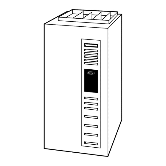
Variable-speed 2-stage
electronic condensing furnace
Hide thumbs
Also See for 58MVP:
- Installation, start-up, and operating instructions manual (53 pages) ,
- Troubleshooting manual (49 pages) ,
- Product data (21 pages)
Advertisement
Quick Links
INDEX
Instructions .....................................................................................1
Example ..........................................................................................1
Sequence of Operation................................................................2-4
Self-Test Mode..........................................................................2
Heating Mode............................................................................2
Heating Mode-Two Stage.........................................................2
Emergency Heat Mode..........................................................2-3
Cooling Mode ...........................................................................3
Heat Pump Mode ......................................................................3
Continuous Fan Mode ...........................................................3-4
Component Test ........................................................................4
Bypass Humidifier Mode..........................................................4
Dehumidification Mode ............................................................4
Zone Mode ................................................................................4
Start Here........................................................................................5
Service Label/Fault Code Instructions .......................................6-7
Improper Operation With No Flashing Fault Code ......................8
Not Enough Cooling Airflow ........................................................9
High-Fire Temperature Rise Too Low (Cold Blow) ..................10
LEDs 1, 2, 3, or 4 On Solid...................................................10-11
RED LED2 Flashing ....................................................................11
Fault Code 11—No Fault in Recent History Display ................12
Fault Code 12—Blower Calibration Lockout........................12-14
Fault Code 13—Limit Switch Lockout..................................14-15
Fault Code 14—Ignition Lockout................................................16
Fault Code 21—Invalid Model Selection....................................17
Fault Code 22—Set Up Error......................................................17
Fault Code 23—Invalid Blower Airflow Selection...............18-19
Fault Code 24—Secondary Voltage Fuse Is Open................19-20
Fault Code 31—High-Pressure Switch Fault.........................20-22
Fault Code 32—Low-Pressure Switch Fault .........................22-24
Fault Code 33—Limit Switch Fault.......................................24-25
Fault Code 34—Ignition Proving Fault .................................25-26
Fault Code 41—Blower Outside Valid Speed Range ...........26-27
Fault Code 42—Inducer Outside Valid Speed Range...........27-29
Fault Code 43—Pressure Switch Calibration Fault...............29-30
Fault Code 44—Blower Calibration Fault.............................30-31
Cleanup and Start-Up Instructions ..............................................31
STEP
1.
Step 1 tells us to record status of LEDs 1-4 and go to Step 2.
Step 2 asks the question, "Are any LEDs flashing?". If low-pressure switch was
2.
defective, a low-pressure switch fault code would be flashing, so the answer is
"YES." We go to Step 5.
Step 5 asks the question, "Is RED LED2 flashing?". If low-pressure switch was
5.
defective, a low-pressure switch fault code would be flashing, so the answer is
"NO". We go to Step 7.
7.
Step 7 tells us to go to low-pressure switch fault subsection.
Manufacturer reserves the right to discontinue, or change at any time, specifications or designs without notice and without incurring obligations.
Book 1 4
PC 101
Catalog No. 535-894
Tab 6a 8a
Troubleshooting Guide
PAGE
EXAMPLE
Start Here Section
Printed in U.S.A.
Variable-Speed 2-Stage
Electronic Condensing Furnace
APPENDIX A—Board Layout & Wiring Schematic ...........32-33
APPENDIX B—Isolation Circuits ..............................................34
APPENDIX C—Pressure Check Diagram ..................................34
APPENDIX D—Quick Motor Test Procedure ......................35-37
APPENDIX E—Variable-Speed Condensing Furnace Duct
Static and Blower Operation.............................................38-42
APPENDIX F—Quick Reference Information ...........................43
APPENDIX G—Thermostat Staging Algorithm ...................44-45
INSTRUCTIONS
This guide uses your expertise and observations to lead you to the
trouble spot as efficiently as possible. This is only intended as a
guide and should not be used blindly. Your experience and
expertise are of high value when troubleshooting this unit. Do not
disregard all of your instincts.
The microprocessor furnace control was designed with diagnostic
capabilities built in. LEDs are used to flash a fault code which will
lead you to 1 of the subsections as listed in the Index.
You should ALWAYS begin in the START HERE subsection
(see Index for page number) which will guide you to the
appropriate subsection where a minimal number of steps will be
used to correct the problem. If you are very experienced at how
this furnace operates and you suspect the problem is either the
blower motor, inducer motor, or furnace control board, you can use
the quick motor test procedure at the end of the troubleshooting
guide to isolate the problem or direct you to appropriate section in
main troubleshooting guide.
Once in a subsection, read the statement or question. A statement
will have a number in the "GO TO" column. Do whatever the
statement says, then proceed to step indicated in the "GO TO"
column.
If the step is a question (a question will have a number in the
"YES" or "NO" column), answer it "YES" or "NO." If the answer
is "YES," go to step indicated in "YES" column. If the answer is
"NO," go to step indicated in "NO" column.
Let's try our guide out using the EXAMPLE section below, and
see how it works. Suppose that the problem is a defective
low-pressure switch (for example will not make). This is an
internal problem and cannot simply be seen. We go to the START
HERE section to Step 1.
YES
—
—
Form 58MVP-1SM
58MVP
NO
GO TO
—
2
5
3
—
6
7
—
—
INDEX
Pg 1
4-95
Replaces: New
Advertisement

Related Manuals for Carrier 58MVP


Summary of Contents for Carrier 58MVP
-
Page 1: Troubleshooting Guide
Manufacturer reserves the right to discontinue, or change at any time, specifications or designs without notice and without incurring obligations. Book 1 4 PC 101 Catalog No. 535-894 Printed in U.S.A. Form 58MVP-1SM Pg 1 4-95 Replaces: New Tab 6a 8a... -
Page 2: Sequence Of Operation
SEQUENCE OF OPERATION The reduction in speed in low heat is to optimize combustion for maximum efficiency. 7. Blower on delay—The blower starts 60 sec after flame sense Furnace control must be grounded for proper operation, or if cycle started in low heat or 35 sec after flame sense if cycle control will lock out. - Page 3 2. Blower on—The blower motor is turned on IMMEDIATELY operates at cooling speed. When heat pump defrost is required, and slowly increases to maximum speed as soon as a call for R-W/W1 circuits close starting gas heat cycle, and blower adjusts heat is received.
- Page 4 NOTE: The blower starts at approximately 400-500 RPM. After When items 1-5 have been completed, the following will occur: 20 sec, the motor is turned off for 1/10 of a sec where a coast down 1. The control center goes through a brief self test. This self test calibration is done to evaluate resistance of the conditioned air takes approximately 2 sec to complete.
-
Page 5: Cooling Airflow
START HERE—If a problem exists, the service technician should always begin troubleshooting here. STEP GO TO Remove main furnace door first. DO NOT REMOVE BLOWER ACCESS PANEL! Record status of LEDs 1-4. See Service Label/Fault Code Instructions — — (Fig. 1). Are any LEDs flashing? —... - Page 7 FUSE 1 2 3 4 5 6 7 8 SETUP SW,(SW1-8)
- Page 8 IMPROPER OPERATION WITH NO FLASHING FAULT CODE—Generally, this indicates there is no power to furnace control board. STEP GO TO Make sure power is on. — — Remove blower access panel and depress door switch. Use a piece of tape to —...
- Page 9 NOT ENOUGH COOLING AIRFLOW—Generally, this indicates the Y/Y2 thermostat lead is not properly connected. STEP GO TO Remove blower access panel and depress door switch. Use a piece of tape to — — hold switch closed. Wait a few sec for self test before proceeding to next step. Make sure thermostat is calling for cooling.
- Page 10 HIGH-FIRE TEMPERATURE TOO LOW—Generally, this indicates the HIGH/LOW solenoid in gas valve GV has failed or furnace is extremely underfired. STEP GO TO Turn power off and remove blower access panel. Make sure thermostat is NOT — — calling for heat. Depress door switch.
- Page 11 STEP GO TO Turn power off and reconnect thermostat leads to furnace control board. — — Turn power on. — — Does RED LED2 turn back ON? — Disconnect all thermostat leads from thermostat control board. — — Put setup switch SW-1 in ON position and jumper R, W/W1, and Y/Y2 thermo- —...
-
Page 12: Fault Code
Fault Code 11 NO FAULT IN RECENT HISTORY DISPLAY—This indicates 1 of the following: • No faults have occurred in the last 5 previous cycles and setup switch SW-1 is in ON position. • The fault history can be cleared by jumpering R, W/W1, and Y/Y2 thermostat leads simultaneously while setup switch SW-1 is in ON position. - Page 13 STEP GO TO Connect a DC voltmeter across ORANGE (+) and VIOLET (-) wires at connec- tor PL13, then repeat the COMPONENT TEST by turning setup switch SW-6 — OFF and then back ON. Do you see approximately the same DC voltages across ORANGE and VIOLET wires that you saw in Step 15? Replace blower motor.
- Page 14 STEP GO TO Disconnect all thermostat leads from furnace control board. If blower motor is — — running, wait until it stops. Jumper R and G thermostat terminals. Observe operation of furnace for next 30 — — sec. Approximately 20 sec after energizing G thermostat terminal, does blower motor pause briefly (less than 1/2 sec)? —...
- Page 15 STEP GO TO The bypass is oversized. Adjust damper or replace with properly sized bypass. — — Disconnect jumper wire across R and W/W1 thermostat terminals and wait until — — blower stops. Does the installation have modulating zone dampers? —...
- Page 16 Fault Code 14 IGNITION LOCKOUT—This fault indicates the system failed to ignite gas and prove flame in 4 attempts. Control will auto-reset in 3 hr. This fault could also indicate the gas valve relay GVR on furnace control board is stuck closed or there is a miswire/short to gas valve wiring.
- Page 17 Fault Code 21 INVALID MODEL SELECTION—Personality connector PL5 is either not connected or jumpered wrong. STEP GO TO Turn power off and remove blower access panel. — — Is personality connector PL5 properly wired per furnace model size chart on —...
- Page 18 Fault Code 23 INVALID BLOWER AIRFLOW SELECTION—This fault indicates improper A/C or CF switch setting. The -14 units can deliver sufficient airflow for 1-1/2 to 3-1/2 tons A/C and 600 to 1400 CFM for continuous fan. The -20 unit can deliver sufficient airflow for 2 to 5 tons A/C and 800 to 2000 CFM for continuous fan. If fault code is flashing, unit still operates, but it defaults to closest allowable airflow.
- Page 19 Table 4—Two-Speed AC/HP Airflow Requirements (CFM) OUTDOOR UNIT CAPACITY A/C Setting 3 Tons—1200 4 Tons—1600 5 Tons—2000 CF Setting 1000 1000 Fault Code 24 SECONDARY VOLTAGE FUSE IS OPEN—Indicates fuse is open and there is a short in low-voltage wiring. STEP GO TO Turn power off and remove blower access panel.
- Page 20 STEP GO TO Jumper R, G, and Y/Y2 thermostat terminals on furnace control board. — — Does Fault Code 24 occur when G and Y/Y2 are energized? — Reconnect all thermostat leads (except HUM terminal if used) to furnace control —...
- Page 21 STEP GO TO Go to page number indicated in Index for CLEANUP AND START-UP — — INDEX INSTRUCTIONS. Does fault occur within 5 sec after W/W1 is energized? — Do you have 24v between the N.O. (Normally Open) contact on high-pressure —...
- Page 22 STEP GO TO Turn power off and disconnect jumper wire across R, W/W1, and W2 thermo- — — stat terminals. Connect 1 side of a slope manometer with a tee to collector box pressure tap. Connect other side with a tee to gas valve air pressure fitting. Refer to pressure —...
- Page 23 STEP GO TO At start of cycle as inducer is ramping up, does low-pressure switch LPS make — then break? Does fault occur 45 sec after call for heat? — Do you have 24v between C (Common) on low-pressure switch LPS and Com —...
- Page 24 STEP GO TO Check Inducer PW line. To do this, disconnect PL7 from inducer motor and connect a DC voltmeter across terminals PL7-2 BROWN (+) and PL7-10 YEL- LOW (-) then run COMPONENT TEST by turning setup switch SW-6 ON. Does voltage across PL7-2 and PL7-10 change between states as shown below? —...
-
Page 25: Ignition Lockout
STEP GO TO Does fault occur after blower stops? — Increase blower off delay time to 225 sec by putting both setup switches SW-7 — — and SW-8 in ON position. Does furnace have proper limit switch, limit shield, blower baffle (if used), rear air baffle (if used), and auxiliary limit switch? If so, are limit switch, limit shield, —... - Page 26 STEP GO TO Fix problem. — — Put setup switch SW-6 for COMPONENT TEST in OFF position. — — Jumper R and W/W1 thermostat terminals on furnace control board. — — Connect an AC voltmeter across BLUE and GREEN wires to gas valve GV. —...
- Page 27 STEP GO TO Go to page number indicated in Index for CLEANUP AND STARTUP — — INDEX INSTRUCTIONS. Does blower motor suddenly stop 10 sec before fault is signaled? — Turn power off and disconnect jumper wire across R and W/W1 thermostat ter- —...
- Page 28 STEP GO TO Replace furnace control board. — — Disconnect jumper wire across R and W/W1 thermostat terminals and put setup — — switch SW-4 for EMER. HEAT in OFF position. Turn power on and wait a few sec for self test before proceeding to next step. —...
- Page 29 STEP GO TO Turn power on and wait several sec, then jumper R, W/W1, and W2 thermostat — — terminals on furnace control board. Does fault occur a few sec after high-pressure switch HPS makes? NOTE: Check for 24v between the N.O. (Normally Open) contact on high- —...
- Page 30 STEP GO TO The ORANGE wire from low-pressure switch LPS to furnace control board is — — not making good connection. Repair wire or replace harness. Turn power off and disconnect jumper wire across R, W/W1, and W2 thermo- stat terminals. Disconnect BROWN wire from N.O. (Normally Open) contact on —...
- Page 31 STEP GO TO Turn power off, wait 30 sec, then restore power. Reset thermostat. Observe op- eration of furnace through 1 cooling cycle. — — NOTE: Blower access panel must be in place. Does Fault Code 44 occur? — You have excessive restriction in air delivery system. Check filter(s) and duct- work.
-
Page 32: Board Layout And Schematic
Appendix A Board Layout and Schematic P/N HK42FZ003 P/N HK42FZ012 SURFACE IGNITOR CONNECTOR EAC-ELECTRONIC AIR CLEANER TERMINALS (115-VAC 1 AMP MAX) 115-V CONNECTORS (SEE DETAILS ABOVE) PRESSURE SWITCH CONNECTOR PL2 MAIN HARNESS HUM-HUMIDIFIER CONNECTOR TERMINAL (24-VAC 0.5 AMP MAX) MAIN BLOWER CONTROL WIRE 24-V THERMOSTAT CONNECTOR... - Page 34 Appendix B Isolation Circuits FURNACE CONTROL THERMOSTAT –FIELD-SUPPLIED FIELD-SUPPLIED BOARD 24-VAC SPST RELAY 24-VAC (40VA) TRANSFORMER 120VAC OUTDOOR UNIT THERMOSTAT FURNACE OUTDOOR FIELD-SUPPLIED UNIT CONTROL 24-VAC SPST RELAYS BOARD A95098 A95097 Fig. 3—Isolation of Outdoor Unit with a Separate Fig. 2—Isolation of W/W1 and Y/Y2 24-v Supply Thermostat Circuits Appendix C...
- Page 35 Appendix D Quick Motor Test Procedure In an effort to provide a method of troubleshooting inducer and blower motor by themselves, the following procedure may save you some time in the event any of the following fault codes are the reason for service call (12, 32, 41, 42, or 44). If you get any other fault code, you should use main troubleshooting guide to isolate problem.
- Page 36 STEP GO TO Connect a DC voltmeter across terminals PL1-6 BROWN (+) and PL1-5 OR- ANGE (-) on furnace control board. Repeat COMPONENT TEST by turning setup switch SW-6 OFF and then back ON. Does voltage across BROWN and ORANGE wires change between states as shown below? —...
- Page 37 STEP GO TO Check RPM feedback line. To do this, connect a DC voltmeter across terminals PL3-2 ORANGE (+) and PL3-3 VIOLET (-). Repeat COMPONENT TEST by turning setup switch SW-6 OFF and then back ON. Does voltage across OR- ANGE and VIOLET wires change between states as shown below? —...
- Page 38 Appendix E Variable-Speed Condensing Furnace Duct Static and Blower Operation This variable-speed furnace has an Integrated Control and Motor called an ICM. This ICM is controlled as stated in Sequence of Operation section. This furnace does a good job compensating for an improperly sized duct system, but this ICM is not a fix for all bad ductwork. This troubleshooting guide has shown that the blower does a calibration 20 sec at start of any operation of ICM.
- Page 39 Air Delivery Curves AIR DELIVERY CURVE — 040-14 AIR DELIVERY CURVE — 060-14 Constant System Constant System HIGH Curves Curves HEAT HIGH HEAT HEAT HEAT ⁄ ⁄ ⁄ 2 Ton ⁄ 3 Ton ⁄ 2 Ton ⁄ 3 Ton 1000 1100 1200 1300...
- Page 40 Static Pressure Reading Location Diagrams COMBUSTION AIR PIPE VENT PIPE OUTDOOR UNIT A/C COIL SUPPLY STATIC HUMIDIFIER INCLINE MANOMETER RETURN STATIC GAS-FIRED WATER HEATER ELECTRONIC AIR CLEANER INCLINE MANOMETER AIRFLOW Basement — Upflow Application A95090 Upflow Total Static Pressure Reading Locations ELECTRONIC AIR CLEANER RETURN STATIC...
- Page 41 RETURN STATIC COMBUSTION–AIR PIPE VENT PIPE INCLINE MANOMETER ELECTRONIC AIR CLEANER SUPPLY STATIC FURNACE CONDENSATE DRAIN AIR CONDITIONING COIL REFRIGERATION INCLINE MANOMETER PIPING AIRFLOW Attic — Horizontal Application A95092 Horizontal Right and Left Airflow Total Static Pressure Reading Locations Tools Needed: Pitot Tube Incline Manometer/Magnahelic Example 1...
- Page 42 Duct Static Check Sheet Furnace: Indoor Coil: Model Number Model Number Serial Number Serial Number Position? U/F D/F H/R H/L Outdoor Unit: Model Number Thermostat Serial Number Electronic Air Cleaner What type of media filter is being used? What is static pressure drop across filter? At what CFM? Does fault code go away when you remove filter? What Zone System is applied?
-
Page 43: Quick Reference Information
Appendix F Quick Reference Information PRESSURE SWITCH MAKE/BREAK POINTS HIGH-PRESSURE SWITCH LOW-PRESSURE SWITCH UNIT SIZE (BTUH) Make Point Break Point Make Point Break Point 1.63 in. wc ± 0.05 0.60 in. wc ± 0.05 40,000 1.81 in. wc max 0.75 in. wc max 60,000 1.63 in. - Page 44 Appendix G Thermostat Staging Algorithm • Unit Default: Algorithm is initiated with Low Heat for 16 minutes. If call for heat still exists, unit transfers into High Heat until thermostat is satisfied. • Low Heat run time is calculated based on previous heating cycle. •...
-
Page 46: Service Training
[ ] Classroom Service Training A94328 Copyright 1995 CARRIER Corp. • 7310 W. Morris St. • Indianapolis, IN 46231 58mvp1sm Manufacturer reserves the right to discontinue, or change at any time, specifications or designs without notice and without incurring obligations.
Need help?
Do you have a question about the 58MVP and is the answer not in the manual?
Questions and answers