
Related Manuals for Nokia RM-627


Summary of Contents for Nokia RM-627
- Page 1 Nokia Customer Care Service Manual RM-627 (Nokia X5-01; L3&4) Mobile Terminal Part No: (Issue 1) COMPANY CONFIDENTIAL Copyright © 2010 Nokia. All rights reserved.
- Page 2 RM-627 Amendment Record Sheet Amendment Record Sheet Amendment No Date Inserted By Comments Issue 1 6/2010 Page ii COMPANY CONFIDENTIAL Issue 1 Copyright © 2010 Nokia. All rights reserved.
- Page 3 Nokia operates a policy of continuous development. Nokia reserves the right to make changes and improvements to any of the products described in this document without prior notice. Under no circumstances shall Nokia be responsible for any loss of data or income or any special, incidental, consequential or indirect damages howsoever caused.
- Page 4 WCDMA networks and cause problems to 3G cellular phone communication in a wide area. • During testing never activate the GSM or WCDMA transmitter without a proper antenna load, otherwise GSM or WCDMA PA may be damaged. Page iv COMPANY CONFIDENTIAL Issue 1 Copyright © 2010 Nokia. All rights reserved.
- Page 5 Use only approved accessories and batteries. Do not connect incompatible products. CONNECTING TO OTHER DEVICES When connecting to any other device, read its user’s guide for detailed safety instructions. Do not connect incompatible products. Issue 1 COMPANY CONFIDENTIAL Page v Copyright © 2010 Nokia. All rights reserved.
- Page 6 All of the above suggestions apply equally to the product, battery, charger or any accessory. Page vi COMPANY CONFIDENTIAL Issue 1 Copyright © 2010 Nokia. All rights reserved.
- Page 7 RM-627 ESD protection ESD protection Nokia requires that service points have sufficient ESD protection (against static electricity) when servicing the phone. Any product of which the covers are removed must be handled with ESD protection. The SIM card can be replaced without ESD protection if the product is otherwise ready for use.
-
Page 8: Battery Information
Batteries' performance is particularly limited in temperatures well below freezing. Do not dispose of batteries in a fire! Dispose of batteries according to local regulations (e.g. recycling). Do not dispose as household waste. Page viii COMPANY CONFIDENTIAL Issue 1 Copyright © 2010 Nokia. All rights reserved. - Page 9 Our policy is of continuous development; details of all technical modifications will be included with service bulletins. While every endeavour has been made to ensure the accuracy of this document, some errors may exist. If any errors are found by the reader, NOKIA MOBILE PHONES Business Group should be notified in writing/e- mail. Please state: •...
- Page 10 RM-627 Company policy (This page left intentionally blank.) Page x COMPANY CONFIDENTIAL Issue 1 Copyright © 2010 Nokia. All rights reserved.
- Page 11 Nokia X5-01; L3&4 Service Manual Structure 1 General information 2 Service Devices and Service Concepts 3 BB Troubleshooting and Manual Tuning Guide 4 RF troubleshooting 5 System Module Glossary Issue 1 COMPANY CONFIDENTIAL Page xi Copyright © 2010 Nokia. All rights reserved.
- Page 12 RM-627 Nokia X5-01; L3&4 Service Manual Structure (This page left intentionally blank.) Page xii COMPANY CONFIDENTIAL Issue 1 Copyright © 2010 Nokia. All rights reserved.
- Page 13 Nokia Customer Care 1 — General information Issue 1 COMPANY CONFIDENTIAL Page 1 – 1 Copyright © 2010 Nokia. All rights reserved.
- Page 14 RM-627 General information (This page left intentionally blank.) Page 1 – 2 COMPANY CONFIDENTIAL Issue 1 Copyright © 2010 Nokia. All rights reserved.
-
Page 15: Table Of Contents
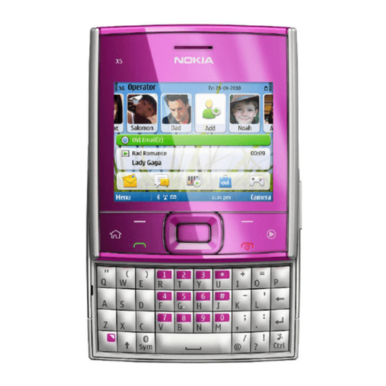
Table 2 Car accessories ............................1–7 Table 3 Headsets ..............................1–7 Table 4 Cables ................................ 1–7 List of Figures Figure 1 RM-627 (Nokia X5–01) product picture ....................1–5 Issue 1 COMPANY CONFIDENTIAL Page 1 – 3 Copyright © 2010 Nokia. All rights reserved. - Page 16 RM-627 General information (This page left intentionally blank.) Page 1 – 4 COMPANY CONFIDENTIAL Issue 1 Copyright © 2010 Nokia. All rights reserved.
-
Page 17: Product Selection
RM-627 General information Product selection RM-627 (Nokia X5–01) is a GSM/WCDMA dual mode phone, supporting EGSM850/900/1800/1900 and WCDMA bands I, II and VIII. Figure 1 RM-627 (Nokia X5–01) product picture Phone features Display and keypad features • 2.36” QVGA 18 bit color display in landscape orientation •... -
Page 18: Software And User Interface Features
• Nokia X5–01 phone • Nokia Battery BL-5F • Travel Charger AC-6 • Nokia Wired Headset WH-102 • Nokia Micro USB Cable CA-101D • Nokia MU-37, 2 GB micro SD • User Guide • Symbian Leaflet • Phone Leaflet Page 1 – 6... -
Page 19: Technical Specifications
Main RF characteristics for GSM850/900/1800/1900 and WCDMA band I, II and VIII phones Parameter Unit Cellular system GSM850, EGSM900, GSM1800/1900, WCDMA I (2100), WCDMA II (1900) and WCDMA VIII (900) Issue 1 COMPANY CONFIDENTIAL Page 1 – 7 Copyright © 2010 Nokia. All rights reserved. - Page 20 Number of RF channels GSM850: 124 GSM900: 174 GSM1800: 374 GSM1900: 299 WCDMA I (2100): 277 WCDMA II (1900): 289 WCDMA VIII (900): 152 Channel spacing 200 kHz Page 1 – 8 COMPANY CONFIDENTIAL Issue 1 Copyright © 2010 Nokia. All rights reserved.
-
Page 21: Battery Endurance
Condensed or dripping water may cause intermittent malfunctions. Protection against dripping water has to be implemented in (enclosure) mechanics. Continuous dampness will cause permanent damage to the module. Issue 1 COMPANY CONFIDENTIAL Page 1 – 9 Copyright © 2010 Nokia. All rights reserved. - Page 22 RM-627 General information (This page left intentionally blank.) Page 1 – 10 COMPANY CONFIDENTIAL Issue 1 Copyright © 2010 Nokia. All rights reserved.
- Page 23 Nokia Customer Care 2 — Service Devices and Service Concepts Issue 1 COMPANY CONFIDENTIAL Page 2 – 1 Copyright © 2010 Nokia. All rights reserved.
- Page 24 RM-627 Service Devices and Service Concepts (This page left intentionally blank.) Page 2 – 2 COMPANY CONFIDENTIAL Issue 1 Copyright © 2010 Nokia. All rights reserved.
-
Page 25: Table Of Contents
Figure 6 Service concept for RF testing and RF/BB tuning ................2–16 Figure 7 Service concept for RF testing and RF/BB tuning ................2–17 Figure 8 WLAN functionality testing concept with SB-7................. 2–18 Issue 1 COMPANY CONFIDENTIAL Page 2 – 3 Copyright © 2010 Nokia. All rights reserved. - Page 26 RM-627 Service Devices and Service Concepts (This page left intentionally blank.) Page 2 – 4 COMPANY CONFIDENTIAL Issue 1 Copyright © 2010 Nokia. All rights reserved.
-
Page 27: Service Devices
The table below gives a short overview of service devices that can be used for testing, error analysis, and repair of product RM-627. For the correct use of the service devices, and the best effort of workbench setup, please refer to various concepts. - Page 28 4 Connect an FBUS cable (if necessary). 5 Start Phoenix service software. Note: Phoenix enables CU-4 regulators via USB when it is started. Reconnecting the power supply requires a Phoenix restart. Page 2 – 6 COMPANY CONFIDENTIAL Issue 1 Copyright © 2010 Nokia. All rights reserved.
-
Page 29: Fps-21
In order to access the SD memory card slots inside FPS-21, the prommer needs to be opened by removing the front panel, rear panel and heatsink from the prommer body. Issue 1 COMPANY CONFIDENTIAL Page 2 – 7 Copyright © 2010 Nokia. All rights reserved. - Page 30 Bluetooth. An ACP-8x charger is needed for BER testing and an AXS-4 cable in case of cordless interface usage testing . Sales package includes: • SB-6 test box • Installation and warranty information Page 2 – 8 COMPANY CONFIDENTIAL Issue 1 Copyright © 2010 Nokia. All rights reserved.
- Page 31 WLAN test requires defined position for the device. SRT-6 Opening tool SRT-6 is used to open phone covers. Note: The SRT-6 is included in the Nokia Standard Toolkit. SS-46 Interface adapter SS-46 acts as an interface adapter between the flash adapter and FPS-20/FPS-21.
-
Page 32: Cables
The table below gives a short overview of service devices that can be used for testing, error analysis, and repair of product RM-627. For the correct use of the service devices, and the best effort of workbench setup, please refer to various concepts. -
Page 33: Ca-89Ds
Power cable The PCS-1 power cable (DC) is used with a docking station, a module jig or a control unit to supply a controlled voltage. Issue 1 COMPANY CONFIDENTIAL Page 2 – 11 Copyright © 2010 Nokia. All rights reserved. -
Page 34: Service Concepts
POS (Point of Sale) flash concept Figure 2 POS flash concept Type Description Product specific tools BL-5F Battery Other tools FLS-5 POS flash dongle PC with Phoenix service software Page 2 – 12 COMPANY CONFIDENTIAL Issue 1 Copyright © 2010 Nokia. All rights reserved. -
Page 35: Flash Concept With Fps-21
Other devices FPS-21 Flash prommer box AC-35 Power supply PK-1 SW security device SS-46 Interface adapter PC with Phoenix service software Cables CA-89DS Service cable Issue 1 COMPANY CONFIDENTIAL Page 2 – 13 Copyright © 2010 Nokia. All rights reserved. -
Page 36: Flash Concept With Fps-21
Power supply PK-1 SW security device SS-62 Flash adapter base SX-4 Smart card (for DCT-4 generation mobile device programming) PC with Phoenix service software Cables Page 2 – 14 COMPANY CONFIDENTIAL Issue 1 Copyright © 2010 Nokia. All rights reserved. -
Page 37: Module Jig Service Concept
Other devices CU-4 Control unit FPS-21 Flash prommer box PK-1/PKD-1 SW security device SX-4 Smart card PC with VPOS and Phoenix service software Measurement equipment Issue 1 COMPANY CONFIDENTIAL Page 2 – 15 Copyright © 2010 Nokia. All rights reserved. -
Page 38: Service Concept For Rf Testing And Rf/Bb Tuning
Figure 6 Service concept for RF testing and RF/BB tuning Type Description Product specific devices MJ-264 Module jig Other devices CU-4 Control unit PK-1 SW security device SX-4 Smart card Measurement equipment Page 2 – 16 COMPANY CONFIDENTIAL Issue 1 Copyright © 2010 Nokia. All rights reserved. -
Page 39: Bluetooth Testing Concept With
Figure 7 Service concept for RF testing and RF/BB tuning Type Description Product specific devices FS-145 Flash adapter Other devices CU-4 Control unit SS-62 Flash adapter base PK-1 SW security device SX-4 Smart card Issue 1 COMPANY CONFIDENTIAL Page 2 – 17 Copyright © 2010 Nokia. All rights reserved. -
Page 40: Wlan Functionality Testing Concept With
Other tools CU-4 Control unit PCS-1 DC power cable PK-1 SW Security device Note: PK-1 can be used instead of PKD-1. SS-62 Generic base adapter Cables Page 2 – 18 COMPANY CONFIDENTIAL Issue 1 Copyright © 2010 Nokia. All rights reserved. - Page 41 RM-627 Service Devices and Service Concepts Type Description PCS-1 Power cable DAU-9S Cable Standard USB cable Issue 1 COMPANY CONFIDENTIAL Page 2 – 19 Copyright © 2010 Nokia. All rights reserved.
- Page 42 RM-627 Service Devices and Service Concepts (This page left intentionally blank.) Page 2 – 20 COMPANY CONFIDENTIAL Issue 1 Copyright © 2010 Nokia. All rights reserved.
- Page 43 Nokia Customer Care 3 — BB Troubleshooting and Manual Tuning Guide Issue 1 COMPANY CONFIDENTIAL Page 3 – 1 Copyright © 2010 Nokia. All rights reserved.
- Page 44 RM-627 BB Troubleshooting and Manual Tuning Guide (This page left intentionally blank.) Page 3 – 2 COMPANY CONFIDENTIAL Issue 1 Copyright © 2010 Nokia. All rights reserved.
-
Page 45: Sb-7
Earpiece troubleshooting ........................3–45 IHF troubleshooting ..........................3–46 Microphone troubleshooting ........................3–47 Vibra troubleshooting........................... 3–48 Bluetooth and FM radio troubleshooting ......................3–49 Bluetooth troubleshooting .......................... 3–49 Issue 1 COMPANY CONFIDENTIAL Page 3 – 3 Copyright © 2010 Nokia. All rights reserved. - Page 46 Figure 14 Single-ended output waveform of the HP_in_Ext_out loop when microphone is connected. 3–41 Figure 15 WLAN circuitry ........................... 3–51 Figure 16 WLAN auto tune settings........................3–57 Figure 17 WLAN autotuning results ......................... 3–58 Page 3 – 4 COMPANY CONFIDENTIAL Issue 1 Copyright © 2010 Nokia. All rights reserved.
-
Page 47: Baseband Self Tests In Phoenix
Always start the troubleshooting procedure by running the Phoenix self tests. If a test fails, please follow the diagram below. If the phone is dead and you cannot perform the self tests, go to Dead or jammed device troubleshooting (page 3–7 ) Issue 1 COMPANY CONFIDENTIAL Page 3 – 5 Copyright © 2010 Nokia. All rights reserved. - Page 48 RM-627 BB Troubleshooting and Manual Tuning Guide Troubleshooting flow Page 3 – 6 COMPANY CONFIDENTIAL Issue 1 Copyright © 2010 Nokia. All rights reserved.
-
Page 49: Power And Charging Troubleshooting
RM-627 BB Troubleshooting and Manual Tuning Guide Power and charging troubleshooting Dead or jammed device troubleshooting Troubleshooting flow Issue 1 COMPANY CONFIDENTIAL Page 3 – 7 Copyright © 2010 Nokia. All rights reserved. -
Page 50: Power Key Troubleshooting
RM-627 BB Troubleshooting and Manual Tuning Guide Power key troubleshooting Troubleshooting flow Page 3 – 8 COMPANY CONFIDENTIAL Issue 1 Copyright © 2010 Nokia. All rights reserved. -
Page 51: General Voltage Checking Troubleshooting
RM-627 BB Troubleshooting and Manual Tuning Guide General voltage checking troubleshooting Troubleshooting flow Issue 1 COMPANY CONFIDENTIAL Page 3 – 9 Copyright © 2010 Nokia. All rights reserved. -
Page 52: General Power Checking
VMEM Pearl/Gazoo microSD Disabled in sleep USB charging troubleshooting Context For instructions regarding USB charging troubleshooting, see section USB charging troubleshooting (page 3–20 ) Page 3 – 10 COMPANY CONFIDENTIAL Issue 1 Copyright © 2010 Nokia. All rights reserved. -
Page 53: Clocking Troubleshooting
RM-627 BB Troubleshooting and Manual Tuning Guide Clocking troubleshooting Troubleshooting flow Issue 1 COMPANY CONFIDENTIAL Page 3 – 11 Copyright © 2010 Nokia. All rights reserved. -
Page 54: Interface Troubleshooting
RM-627 BB Troubleshooting and Manual Tuning Guide Interface troubleshooting Flash programming fault troubleshooting Troubleshooting flow - Page 1 of 2 Page 3 – 12 COMPANY CONFIDENTIAL Issue 1 Copyright © 2010 Nokia. All rights reserved. - Page 55 BB Troubleshooting and Manual Tuning Guide Troubleshooting flow - Page 2 of 2 Figure 9 Flashing pic 1. Take single trig measurement for the rise of the BSI signal Issue 1 COMPANY CONFIDENTIAL Page 3 – 13 Copyright © 2010 Nokia. All rights reserved.
- Page 56 RM-627 BB Troubleshooting and Manual Tuning Guide Figure 10 Flashing pic 2. Take single trig measurement for the rise of the BSI signal Page 3 – 14 COMPANY CONFIDENTIAL Issue 1 Copyright © 2010 Nokia. All rights reserved.
-
Page 57: Sim Card Troubleshooting
RM-627 BB Troubleshooting and Manual Tuning Guide SIM card troubleshooting Troubleshooting flow Issue 1 COMPANY CONFIDENTIAL Page 3 – 15 Copyright © 2010 Nokia. All rights reserved. - Page 58 RM-627 BB Troubleshooting and Manual Tuning Guide Page 3 – 16 COMPANY CONFIDENTIAL Issue 1 Copyright © 2010 Nokia. All rights reserved.
-
Page 59: Microsd Card Troubleshooting
RM-627 BB Troubleshooting and Manual Tuning Guide MicroSD card troubleshooting Troubleshooting flow Issue 1 COMPANY CONFIDENTIAL Page 3 – 17 Copyright © 2010 Nokia. All rights reserved. -
Page 60: Usb Troubleshooting
RM-627 BB Troubleshooting and Manual Tuning Guide USB troubleshooting USB data interface troubleshooting Troubleshooting flow - Page 1 of 2 Page 3 – 18 COMPANY CONFIDENTIAL Issue 1 Copyright © 2010 Nokia. All rights reserved. - Page 61 RM-627 BB Troubleshooting and Manual Tuning Guide Troubleshooting flow - Page 2 of 2 Issue 1 COMPANY CONFIDENTIAL Page 3 – 19 Copyright © 2010 Nokia. All rights reserved.
-
Page 62: Usb Charging Troubleshooting
RM-627 BB Troubleshooting and Manual Tuning Guide USB charging troubleshooting Troubleshooting flow Page 3 – 20 COMPANY CONFIDENTIAL Issue 1 Copyright © 2010 Nokia. All rights reserved. -
Page 63: User Interface Troubleshooting
• Malfunction of several keys at the same time. This happens when one or more rows or columns in the key matrix are failing (shortcut or open connection). If the failure mode is not clear, start with the Keyboard test in Phoenix. Troubleshooting flow Issue 1 COMPANY CONFIDENTIAL Page 3 – 21 Copyright © 2010 Nokia. All rights reserved. -
Page 64: Keypad Leds Troubleshooting
RM-627 BB Troubleshooting and Manual Tuning Guide Keypad LEDs troubleshooting Troubleshooting flow Page 3 – 22 COMPANY CONFIDENTIAL Issue 1 Copyright © 2010 Nokia. All rights reserved. -
Page 65: Mr Sensor Troubleshooting
RM-627 BB Troubleshooting and Manual Tuning Guide MR sensor troubleshooting Troubleshooting flow Issue 1 COMPANY CONFIDENTIAL Page 3 – 23 Copyright © 2010 Nokia. All rights reserved. -
Page 66: Accelerometer Self Test Troubleshooting
Make sure before starting the troubleshooting that there are no vibrations or movements which could have an impact on the analysis. The three different axes for the accelerometer are illustrated in the picture below. Figure 11 Accelerometer axes Page 3 – 24 COMPANY CONFIDENTIAL Issue 1 Copyright © 2010 Nokia. All rights reserved. - Page 67 RM-627 BB Troubleshooting and Manual Tuning Guide Troubleshooting flow Issue 1 COMPANY CONFIDENTIAL Page 3 – 25 Copyright © 2010 Nokia. All rights reserved.
-
Page 68: Display Module Troubleshooting
This means that in case the display is working (image OK), the backlight is faulty. Page 3 – 26 COMPANY CONFIDENTIAL Issue 1 Copyright © 2010 Nokia. All rights reserved. - Page 69 APE ID). 3. Proceed to the display fault troubleshooting flowchart. Phoenix to find the detailed fault mode. Use the Display Test tool in Issue 1 COMPANY CONFIDENTIAL Page 3 – 27 Copyright © 2010 Nokia. All rights reserved.
-
Page 70: Display Fault Troubleshooting
RM-627 BB Troubleshooting and Manual Tuning Guide Display fault troubleshooting Troubleshooting flow Page 3 – 28 COMPANY CONFIDENTIAL Issue 1 Copyright © 2010 Nokia. All rights reserved. -
Page 71: Display Backlight Troubleshooting
RM-627 BB Troubleshooting and Manual Tuning Guide Display backlight troubleshooting Troubleshooting flow Issue 1 COMPANY CONFIDENTIAL Page 3 – 29 Copyright © 2010 Nokia. All rights reserved. -
Page 72: Ambient Light Sensor (Als)
RM-627 BB Troubleshooting and Manual Tuning Guide Ambient light sensor (ALS) ALS troubleshooting Troubleshooting flow Page 3 – 30 COMPANY CONFIDENTIAL Issue 1 Copyright © 2010 Nokia. All rights reserved. -
Page 73: Als Functionality Check
Phoenix and set the phone (e.g. on the table) so that the amount of ambient Connect reference phone to light seen by ALS is as stabile as possible. Phoenix . Start Choose File→Scan Product. Issue 1 COMPANY CONFIDENTIAL Page 3 – 31 Copyright © 2010 Nokia. All rights reserved. - Page 74 If illuminance values differs a lot (difference max. +- 10%), repeat whole ALS re-tuning procedure. 10. To end the calibration, click Close. Page 3 – 32 COMPANY CONFIDENTIAL Issue 1 Copyright © 2010 Nokia. All rights reserved.
-
Page 75: Camera Module Troubleshooting
• Analyse the picture from your PC monitor, full colour setting is recommended • If possible, compare with a picture of the same motive taken with a similar Nokia device • If camera has auto focus: Remember that the white focussing frame which appears when the camera button is pressed halfway down, must turn green for auto focus lock. -
Page 76: Camera Troubleshooting
RM-627 BB Troubleshooting and Manual Tuning Guide Camera troubleshooting Troubleshooting flow Page 3 – 34 COMPANY CONFIDENTIAL Issue 1 Copyright © 2010 Nokia. All rights reserved. -
Page 77: Camera Baseband Troubleshooting
RM-627 BB Troubleshooting and Manual Tuning Guide Camera baseband troubleshooting Troubleshooting flow Issue 1 COMPANY CONFIDENTIAL Page 3 – 35 Copyright © 2010 Nokia. All rights reserved. -
Page 78: Camera No Recognizable Viewfinder Image Troubleshooting
RM-627 BB Troubleshooting and Manual Tuning Guide Camera no recognizable viewfinder image troubleshooting Troubleshooting flow Page 3 – 36 COMPANY CONFIDENTIAL Issue 1 Copyright © 2010 Nokia. All rights reserved. -
Page 79: Camera Bad Image Quality Troubleshooting
RM-627 BB Troubleshooting and Manual Tuning Guide Camera bad image quality troubleshooting Troubleshooting flow Issue 1 COMPANY CONFIDENTIAL Page 3 – 37 Copyright © 2010 Nokia. All rights reserved. -
Page 80: Camera Flash Troubleshooting
Differential external earpiece and internal earpiece outputs can be measured either with a single-ended or a differential probe. When measuring with a single-ended probe each output is measured against the ground. Page 3 – 38 COMPANY CONFIDENTIAL Issue 1 Copyright © 2010 Nokia. All rights reserved. - Page 81 External Mic to XMICP and HSEAR R 16.7 External Earpiece and GND HSEAR L and GND XMICN and HSEAR R and GND HSEAR L and GND Issue 1 COMPANY CONFIDENTIAL Page 3 – 39 Copyright © 2010 Nokia. All rights reserved.
- Page 82 28.1 2540 112mA Internal (calc.) handsfree XMICN and B2102 pads Measurement data Figure 12 Single-ended output waveform of the Ext_in_HP_out measurement when earpiece is connected. Page 3 – 40 COMPANY CONFIDENTIAL Issue 1 Copyright © 2010 Nokia. All rights reserved.
- Page 83 Figure 13 Differential output waveform of the Ext_in_IHF_out out loop measurement when speaker is connected. Figure 14 Single-ended output waveform of the HP_in_Ext_out loop when microphone is connected. Issue 1 COMPANY CONFIDENTIAL Page 3 – 41 Copyright © 2010 Nokia. All rights reserved.
-
Page 84: Internal Earpiece Troubleshooting
RM-627 BB Troubleshooting and Manual Tuning Guide Internal earpiece troubleshooting Troubleshooting flow Page 3 – 42 COMPANY CONFIDENTIAL Issue 1 Copyright © 2010 Nokia. All rights reserved. -
Page 85: Internal Handsfree (Ihf) Troubleshooting
RM-627 BB Troubleshooting and Manual Tuning Guide Internal handsfree (IHF) troubleshooting Troubleshooting flow Issue 1 COMPANY CONFIDENTIAL Page 3 – 43 Copyright © 2010 Nokia. All rights reserved. -
Page 86: Internal Microphone Troubleshooting
The phone should be dry and clean, and no objects must be located in such a way that they close any of the holes. Page 3 – 44 COMPANY CONFIDENTIAL Issue 1 Copyright © 2010 Nokia. All rights reserved. -
Page 87: Earpiece Troubleshooting
RM-627 BB Troubleshooting and Manual Tuning Guide Earpiece troubleshooting Troubleshooting flow Issue 1 COMPANY CONFIDENTIAL Page 3 – 45 Copyright © 2010 Nokia. All rights reserved. -
Page 88: Ihf Troubleshooting
RM-627 BB Troubleshooting and Manual Tuning Guide IHF troubleshooting Troubleshooting flow Page 3 – 46 COMPANY CONFIDENTIAL Issue 1 Copyright © 2010 Nokia. All rights reserved. -
Page 89: Microphone Troubleshooting
RM-627 BB Troubleshooting and Manual Tuning Guide Microphone troubleshooting Troubleshooting flow Issue 1 COMPANY CONFIDENTIAL Page 3 – 47 Copyright © 2010 Nokia. All rights reserved. -
Page 90: Vibra Troubleshooting
RM-627 BB Troubleshooting and Manual Tuning Guide Vibra troubleshooting Troubleshooting flow Page 3 – 48 COMPANY CONFIDENTIAL Issue 1 Copyright © 2010 Nokia. All rights reserved. -
Page 91: Bluetooth And Fm Radio Troubleshooting
RM-627 BB Troubleshooting and Manual Tuning Guide Bluetooth and FM radio troubleshooting Bluetooth troubleshooting Troubleshooting flow Issue 1 COMPANY CONFIDENTIAL Page 3 – 49 Copyright © 2010 Nokia. All rights reserved. -
Page 92: Fm Radio Troubleshooting
RM-627 BB Troubleshooting and Manual Tuning Guide FM radio troubleshooting Troubleshooting flow Page 3 – 50 COMPANY CONFIDENTIAL Issue 1 Copyright © 2010 Nokia. All rights reserved. -
Page 93: Wlan Troubleshooting
WLAN acknowledges the data blocks and so the self test is a good way to confirm that the WLAN module is communicating with the Host. The result column changes to Passed after a few seconds if it is operating properly. Issue 1 COMPANY CONFIDENTIAL Page 3 – 51 Copyright © 2010 Nokia. All rights reserved. - Page 94 This test verifies that the WLAN to BTH co-existence interface signals are properly connected and there are no open circuist or shorts on the four interface signals. The co-existence interface comprises BTH Txconfig, BTH RF Active, BTH Priority, and BTH Frequency. Page 3 – 52 COMPANY CONFIDENTIAL Issue 1 Copyright © 2010 Nokia. All rights reserved.
-
Page 95: Wlan Functional Tests
The difference between the currents in (1) and (2) should be between 190 to 220 mA. When WLAN is ON, the firmware has been downloaded and the WLAN module is in the receive state. When WLAN in OFF, WLAN is powered down. Issue 1 COMPANY CONFIDENTIAL Page 3 – 53 Copyright © 2010 Nokia. All rights reserved. - Page 96 2 To finish the test, Press the Finish button. The difference between the two readings should be approximately 150 mA and measures the transmit current in 11 Mbps, 802.11b mode of operation. Page 3 – 54 COMPANY CONFIDENTIAL Issue 1 Copyright © 2010 Nokia. All rights reserved.
- Page 97 WLAN network. Simply starting an Rx test shows the number of packets detected by the WLAN module as it monitors the network. However, it requires a properly configured WLAN network. Issue 1 COMPANY CONFIDENTIAL Page 3 – 55 Copyright © 2010 Nokia. All rights reserved.
-
Page 98: Wlan Auto Tuning
RF cable. Start Phoenix WLAN autotune window. Check the settings and verify your PC communicates with CMU200 via GPIB. Auto tuning procedure 1 Start tuning by pressing Tune. Page 3 – 56 COMPANY CONFIDENTIAL Issue 1 Copyright © 2010 Nokia. All rights reserved. - Page 99 RM-627 BB Troubleshooting and Manual Tuning Guide Figure 16 WLAN auto tune settings Issue 1 COMPANY CONFIDENTIAL Page 3 – 57 Copyright © 2010 Nokia. All rights reserved.
-
Page 100: Baseband Manual Tuning Guide
• Latest product specific data package, supporting for the variants you want to change the phones to. Certificate restoring without flashing does not require data packages to be installed Page 3 – 58 COMPANY CONFIDENTIAL Issue 1 Copyright © 2010 Nokia. All rights reserved. - Page 101 • When certificate restoring for BB 5 products or IMEI rebuild for DCT-4 products is performed, existing data from Nokia System is programmed in the phone. The phone will be in the same condition as it was when it left the factory for the first time.
- Page 102 SW downgrade which causes the phone to die. 7. Information from phone and Smart Card are read and connection to Tucson server is established. Page 3 – 60 COMPANY CONFIDENTIAL Issue 1 Copyright © 2010 Nokia. All rights reserved.
- Page 103 RM-627 BB Troubleshooting and Manual Tuning Guide 8. Information from Nokia system is retreived and programmed in the phone. 9. After programming, confirmation about successful event is sent to Nokia system. Issue 1 COMPANY CONFIDENTIAL Page 3 – 61 Copyright © 2010 Nokia. All rights reserved.
-
Page 104: Product Code Change
Nokia System, and programmed in the phone. • After successful change, phone specific information in Nokia systems will match the new variant, and it can be used for e.g. certificate restoring. If you perform several product code changes, Nokia system will always be up to date with the latest successful event. - Page 105 RM-627 BB Troubleshooting and Manual Tuning Guide Select “OK” and “SWAP”. Information from phone is read and connection to Tucson server is established. Issue 1 COMPANY CONFIDENTIAL Page 3 – 63 Copyright © 2010 Nokia. All rights reserved.
- Page 106 RM-627 BB Troubleshooting and Manual Tuning Guide If “Flash Product” – option was selected, phone SW is programmed. New data retrieved from Nokia system is programmed in the phone. Page 3 – 64 COMPANY CONFIDENTIAL Issue 1 Copyright © 2010 Nokia. All rights reserved.
- Page 107 RM-627 BB Troubleshooting and Manual Tuning Guide Confirmation about successful event is sent to Nokia system. 10. Phone has now been changed to another variant. If there is need to restore the data, this information will be sent back to phone. Warranty information in NOL will show the current information in about 24 hours.
-
Page 108: Energy Management Calibration
(please refer to the following "Calibration value limits" table), click Write to store the new calibration values to the phone permanent memory. Table 9 Calibration value limits Parameter Min. Max. ADC Offset Page 3 – 66 COMPANY CONFIDENTIAL Issue 1 Copyright © 2010 Nokia. All rights reserved. - Page 109 Write and/or repeat the procedure again. Energy Management Calibration window. 10. To end the procedure, close the Issue 1 COMPANY CONFIDENTIAL Page 3 – 67 Copyright © 2010 Nokia. All rights reserved.
- Page 110 RM-627 BB Troubleshooting and Manual Tuning Guide (This page left intentionally blank.) Page 3 – 68 COMPANY CONFIDENTIAL Issue 1 Copyright © 2010 Nokia. All rights reserved.
- Page 111 Nokia Customer Care 4 — RF troubleshooting Issue 1 COMPANY CONFIDENTIAL Page 4 – 1 Copyright © 2010 Nokia. All rights reserved.
- Page 112 RM-627 RF troubleshooting (This page left intentionally blank.) Page 4 – 2 COMPANY CONFIDENTIAL Issue 1 Copyright © 2010 Nokia. All rights reserved.
- Page 113 Figure 27 Phoenix WCDMA Tx Control window settings................. 4–24 Figure 28 Test points for voltage checking ..................... 4–25 Figure 29 Component reference block diagram....................4–28 Issue 1 COMPANY CONFIDENTIAL Page 4 – 3 Copyright © 2010 Nokia. All rights reserved.
- Page 114 RM-627 RF troubleshooting (This page left intentionally blank.) Page 4 – 4 COMPANY CONFIDENTIAL Issue 1 Copyright © 2010 Nokia. All rights reserved.
-
Page 115: General Rf Troubleshooting
Instructions for finding the faulty component are provided in some cases, but the whole RF block still needs to be replaced even when a single component is faulty. Issue 1 COMPANY CONFIDENTIAL Page 4 – 5 Copyright © 2010 Nokia. All rights reserved. -
Page 116: Rf Key Components
• Cables: RF cable XRS-6, USB cable, GBIP cable and MBUS cable DAU-9S • Signal analyser (TX), signal generator (RX) and RF-splitter or one device including all. Page 4 – 6 COMPANY CONFIDENTIAL Issue 1 Copyright © 2010 Nokia. All rights reserved. -
Page 117: Auto Tuning Procedure
Self tests are recommended to be made when phone is in jig and a 50Ω load connected to the RF connector. Otherwise power tests may fail depending on antenna load Issue 1 COMPANY CONFIDENTIAL Page 4 – 7 Copyright © 2010 Nokia. All rights reserved. - Page 118 RM-627 RF troubleshooting Troubleshooting flow Page 4 – 8 COMPANY CONFIDENTIAL Issue 1 Copyright © 2010 Nokia. All rights reserved.
-
Page 119: Receiver Troubleshooting
The reading should reflect the level of the signal generator (minus losses) ±5dB. When varying the level in the range -30 to -102dBm the reading should then follow within ±5dB. Issue 1 COMPANY CONFIDENTIAL Page 4 – 9 Copyright © 2010 Nokia. All rights reserved. -
Page 120: Gsm Receiver Troubleshooting Flowchart
RM-627 RF troubleshooting GSM receiver troubleshooting flowchart Troubleshooting flow Page 4 – 10 COMPANY CONFIDENTIAL Issue 1 Copyright © 2010 Nokia. All rights reserved. -
Page 121: Wcdma Rx Chain Activation For Manual Measurement
4. Click Start to activate the settings. If the settings are changed later on (for example, change of channel) you have to click Stop and Start again. Issue 1 COMPANY CONFIDENTIAL Page 4 – 11 Copyright © 2010 Nokia. All rights reserved. -
Page 122: Wcdma Rssi Measurement
2. In the RX Power measurement window, select: • Mode: RSSI • Continuous mode 3. Click Start to perform the measurement. Note: WCDMA RSSI measurement is accurate only with WCDMA modulated signal. Page 4 – 12 COMPANY CONFIDENTIAL Issue 1 Copyright © 2010 Nokia. All rights reserved. -
Page 123: Wcdma Receiver Troubleshooting Flowchart
RM-627 RF troubleshooting WCDMA receiver troubleshooting flowchart Troubleshooting flow Issue 1 COMPANY CONFIDENTIAL Page 4 – 13 Copyright © 2010 Nokia. All rights reserved. -
Page 124: Transmitter Troubleshooting
2. In Phoenix, select Testing → GSM → Rf Controls . The RF Controls window opens. Figure 23 Phoenix RF Controls window 3. Make the following settings: Page 4 – 14 COMPANY CONFIDENTIAL Issue 1 Copyright © 2010 Nokia. All rights reserved. - Page 125 Tx Power Level 4. Check the basic TX parameters, using a communication analyser (e.g. CMU200). • Power • Phase error • Modulation • Switching spectrum Issue 1 COMPANY CONFIDENTIAL Page 4 – 15 Copyright © 2010 Nokia. All rights reserved.
- Page 126 RM-627 RF troubleshooting Figure 24 Typical readings 5. Change the power level in RF controls window and make sure the power reading follows accordingly. Page 4 – 16 COMPANY CONFIDENTIAL Issue 1 Copyright © 2010 Nokia. All rights reserved.
- Page 127 You can troubleshoot the GSM transmitter for each GSM band separately, one band at a time. If you want to troubleshoot GSM850, GSM1800 or GSM1900, change the band in the RF controls window and set the communication analyser accordingly. Issue 1 COMPANY CONFIDENTIAL Page 4 – 17 Copyright © 2010 Nokia. All rights reserved.
-
Page 128: Gsm Transmitter Troubleshooting Flowchart
RM-627 RF troubleshooting GSM transmitter troubleshooting flowchart Troubleshooting flow Page 4 – 18 COMPANY CONFIDENTIAL Issue 1 Copyright © 2010 Nokia. All rights reserved. -
Page 129: Wcdma Transmitter Troubleshooting
WCDMA VIII 2788 4. Make the following general settings (the same values for all bands). Note that Max power limit is not checked by default. Issue 1 COMPANY CONFIDENTIAL Page 4 – 19 Copyright © 2010 Nokia. All rights reserved. - Page 130 If settings are changed (eg. new channel selected), you have to click RF Stop and Send again. 6. Check the basic TX parameters using a communication analyser (e.g. CMU200). Page 4 – 20 COMPANY CONFIDENTIAL Issue 1 Copyright © 2010 Nokia. All rights reserved.
- Page 131 RM-627 RF troubleshooting Figure 26 Typical readings Issue 1 COMPANY CONFIDENTIAL Page 4 – 21 Copyright © 2010 Nokia. All rights reserved.
-
Page 132: Wcdma Transmitter Troubleshooting Flowchart
RM-627 RF troubleshooting WCDMA transmitter troubleshooting flowchart Troubleshooting flow Page 4 – 22 COMPANY CONFIDENTIAL Issue 1 Copyright © 2010 Nokia. All rights reserved. -
Page 133: Troubleshooting With Rf-Shield Removed
Supply input to DC/DC conv C7527 3.7V (Vbattery) Note: When using settings as shown in the following Tx Control window, the result at TP4 should be 3.1V. Issue 1 COMPANY CONFIDENTIAL Page 4 – 23 Copyright © 2010 Nokia. All rights reserved. - Page 134 RM-627 RF troubleshooting Figure 27 Phoenix WCDMA Tx Control window settings Page 4 – 24 COMPANY CONFIDENTIAL Issue 1 Copyright © 2010 Nokia. All rights reserved.
- Page 135 RM-627 RF troubleshooting Figure 28 Test points for voltage checking Issue 1 COMPANY CONFIDENTIAL Page 4 – 25 Copyright © 2010 Nokia. All rights reserved.
-
Page 136: Vctcxo Troubleshooting
This table shows the components used for the different bands. It can be used as a reference when troubleshooting which components may or may not be faulty. Page 4 – 26 COMPANY CONFIDENTIAL Issue 1 Copyright © 2010 Nokia. All rights reserved. - Page 137 X means that the component is used for the band in the current column. For further reference, see Component reference schematics on the following page. Issue 1 COMPANY CONFIDENTIAL Page 4 – 27 Copyright © 2010 Nokia. All rights reserved.
- Page 138 RM-627 RF troubleshooting RF block diagram Figure 29 Component reference block diagram Page 4 – 28 COMPANY CONFIDENTIAL Issue 1 Copyright © 2010 Nokia. All rights reserved.
-
Page 139: Antenna
(X7401 and X7402). The non-cellular antenna has two contact springs (X6397 and X6399). Check the shape of the springs and replace if damaged. Issue 1 COMPANY CONFIDENTIAL Page 4 – 29 Copyright © 2010 Nokia. All rights reserved. - Page 140 RM-627 RF troubleshooting (This page left intentionally blank.) Page 4 – 30 COMPANY CONFIDENTIAL Issue 1 Copyright © 2010 Nokia. All rights reserved.
- Page 141 Nokia Customer Care 5 — System Module Issue 1 COMPANY CONFIDENTIAL Page 5 – 1 Copyright © 2010 Nokia. All rights reserved.
- Page 142 RM-627 System Module (This page left intentionally blank.) Page 5 – 2 COMPANY CONFIDENTIAL Issue 1 Copyright © 2010 Nokia. All rights reserved.
- Page 143 5–14 Figure 40 Audio interface ..........................5–15 Figure 41 AV connector............................5–15 Figure 42 Bluetooth interface ........................... 5–16 Figure 43 FM radio interface ..........................5–17 Issue 1 COMPANY CONFIDENTIAL Page 5 – 3 Copyright © 2010 Nokia. All rights reserved.
- Page 144 RM-627 System Module (This page left intentionally blank.) Page 5 – 4 COMPANY CONFIDENTIAL Issue 1 Copyright © 2010 Nokia. All rights reserved.
-
Page 145: Introduction
D3300 WLAN WLAN Size4.0b N6300 Battery BL-5F Battery connector Tabby blade interface X2070 MicroSD connector X3200 RF connector X7400 SIM connector X2700 Charging connector X2000 Issue 1 COMPANY CONFIDENTIAL Page 5 – 5 Copyright © 2010 Nokia. All rights reserved. - Page 146 RM-627 System Module Key component placement Page 5 – 6 COMPANY CONFIDENTIAL Issue 1 Copyright © 2010 Nokia. All rights reserved.
-
Page 147: Energy Management
EM ASIC (N2200). This resistor is located on the main PWB, at a place where the phone temperature is closest to the battery temperature. Battery connector The battery connector is a blade connector. It has three blades; • BSI (Battery size indicator) Issue 1 COMPANY CONFIDENTIAL Page 5 – 7 Copyright © 2010 Nokia. All rights reserved. -
Page 148: Normal And Extreme Voltages
Charging a dead battery Charging of a dead battery has to be carried out via an approved NOKIA charger. Charging of a dead battery via a PC is not allowed, since this procedure does not including a current regulator (the battery can be charged with a too high current level). -
Page 149: Power Key And System Power-Up
CLK600. The clock source is an internal RC oscillator in EM ASIC N2200 (during the power-up sequence) or RAPU SMPS Clk. Bluetooth has a separate 38.4MHz TCXO clock oscillator. Issue 1 COMPANY CONFIDENTIAL Page 5 – 9 Copyright © 2010 Nokia. All rights reserved. -
Page 150: Power Distibution
RM-627 System Module Power distibution Figure 32 Power distribution diagram Page 5 – 10 COMPANY CONFIDENTIAL Issue 1 Copyright © 2010 Nokia. All rights reserved. -
Page 151: Sim Interface
EM ASIC and the microSD card. The microSD card connector is mounted on a separate PWB, the Micro PWB. Figure 34 MicroSD card interface Issue 1 COMPANY CONFIDENTIAL Page 5 – 11 Copyright © 2010 Nokia. All rights reserved. -
Page 152: Usb
Hot swap is supported, which means that USB devices may be plugged in and out at any time. MicroUSB connector This phone is provided with a specific connector for microUSB. Page 5 – 12 COMPANY CONFIDENTIAL Issue 1 Copyright © 2010 Nokia. All rights reserved. -
Page 153: User Interface
Space & <1> Vol - <2> <3> <4> CTRL Left Select Right Down S60-L <5> Return Soft- Soft- S60-R Send Left Right <6> <7> <8> Issue 1 COMPANY CONFIDENTIAL Page 5 – 13 Copyright © 2010 Nokia. All rights reserved. -
Page 154: Ambient Light Sensor (Als) Interface
Figure 39 Ambient light sensor (ALS) interface Audio interface The following block diagram illustrates the audio interface of the phone: Page 5 – 14 COMPANY CONFIDENTIAL Issue 1 Copyright © 2010 Nokia. All rights reserved. -
Page 155: Av Connector
BTHFM module. Bluetooth is physically integrated with FM radio in the BTHFM module ASIC, but from a functional point of view they have nothing in common Issue 1 COMPANY CONFIDENTIAL Page 5 – 15 Copyright © 2010 Nokia. All rights reserved. -
Page 156: Fm Radio Interface
FM radio is physically integrated with Bluetooth in the BTHFM module ASIC, but from a functional point of view FM radio and Bluetooth have nothing in common. Page 5 – 16 COMPANY CONFIDENTIAL Issue 1 Copyright © 2010 Nokia. All rights reserved. -
Page 157: Rf Description
The receiver functions are implemented in the RF ASIC. Signals with different frequencies take different paths, therefore being handled by different components. The principle of GSM and WCDMA is the same. Issue 1 COMPANY CONFIDENTIAL Page 5 – 17 Copyright © 2010 Nokia. All rights reserved. -
Page 158: Transmitter (Tx)
The transmitter functions are implemented in the RF ASIC. Even though the GSM and WCDMA signals are sent via different components, the principle of the transmission is the same. Page 5 – 18 COMPANY CONFIDENTIAL Issue 1 Copyright © 2010 Nokia. All rights reserved. - Page 159 Nokia Customer Care Glossary Issue 1 COMPANY CONFIDENTIAL Page Glossary– 1 Copyright © 2010 Nokia. All rights reserved.
- Page 160 RM-627 Glossary (This page left intentionally blank.) Page Glossary– 2 COMPANY CONFIDENTIAL Issue 1 Copyright © 2010 Nokia. All rights reserved.
- Page 161 Clock Timing Sleep and interrupt block of Tiku Continuous wave D/A-converter Digital-to-analogue converter Digital-to-analogue converter Digital Battery Interface DBus DSP controlled serial bus connected between UPP_WD2 and Helgo Issue 1 COMPANY CONFIDENTIAL Page Glossary– 3 Copyright © 2010 Nokia. All rights reserved.
- Page 162 High speed circuit switched data (data transmission connection faster than GSM) Hardware Input/Output IBAT Battery current Integrated circuit ICHAR Charger current Interface Integrated hands free IMEI International Mobile Equipment Identity Page Glossary– 4 COMPANY CONFIDENTIAL Issue 1 Copyright © 2010 Nokia. All rights reserved.
- Page 163 Software tool of DCT4.x and BB5 Personal Information Management Phase locked loop (Phone) Permanent memory General Purpose IO (PIO), USARTS and Pulse Width Modulators PURX Power-up reset Printed Wiring Board Issue 1 COMPANY CONFIDENTIAL Page Glossary– 5 Copyright © 2010 Nokia. All rights reserved.
- Page 164 Universal Energy Management chip (Enhanced version) UEMEK See UEME User Interface UPnP Universal Plug and Play Universal Phone Processor UPP_WD2 Communicator version of DCT4 system ASIC Page Glossary– 6 COMPANY CONFIDENTIAL Issue 1 Copyright © 2010 Nokia. All rights reserved.
- Page 165 Wideband code division multiple access Watchdog WLAN Wireless local area network XHTML Extensible hypertext markup language Zocus Current sensor (used to monitor the current flow to and from the battery) Issue 1 COMPANY CONFIDENTIAL Page Glossary– 7 Copyright © 2010 Nokia. All rights reserved.
- Page 166 RM-627 Glossary (This page left intentionally blank.) Page Glossary– 8 COMPANY CONFIDENTIAL Issue 1 Copyright © 2010 Nokia. All rights reserved.
Need help?
Do you have a question about the RM-627 and is the answer not in the manual?
Questions and answers