Table of Contents
Advertisement
Quick Links
Download this manual
See also:
User Manual
1
SERVICE MANUAL
Level 1&2
RM-627, RM-648
Transceiver characteristics
Band:
RM-627:
GSM 850/900/1800/1900
WCDMA 900/1900/2100
RM-648:
GSM: 850/900/1800/1900
WCDMA: 850/1900/2100
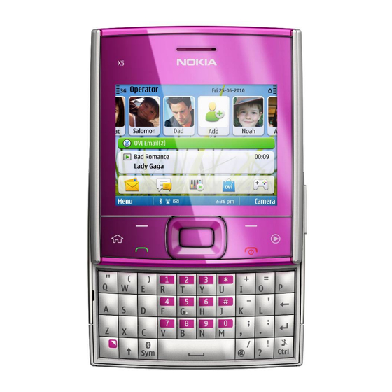
Display:
QVGA (320 x 240 pixels) 2.36" TFT screen, up to 262k
colors
Camera:
5 Mpix EDOF camera with LED flash, 4x Digital
zoom
Operating System:
S60 release 3.2.3
Connections:
Micro USB (USB 2.0)
3.5 mm Nokia AV connector
Micro SD card support up to 32 GB
WLAN 802.11 b/g
Transceiver with BL-5F battery pack
Talk time
GSM 850: 4 h
Other GSM-bands: 5 h
WCDMA: 3.5 h
Note: Talk times are dependent on network
parameters and phone settings
Confidential | Copyright © 2010 Nokia | All rights reserved
Nokia X5-01
RM-627, RM-648
Service Manual Level 1&2
Standby
GSM: Up to 400 hours
WCDMA: Up to 400 hours
Version 4.0
Advertisement
Table of Contents

Related Manuals for Nokia X5-01


Summary of Contents for Nokia X5-01
- Page 1 GSM: Up to 400 hours Other GSM-bands: 5 h WCDMA: Up to 400 hours WCDMA: 3.5 h Note: Talk times are dependent on network parameters and phone settings Confidential | Copyright © 2010 Nokia | All rights reserved Version 4.0...
-
Page 2: Table Of Contents
Battery information......................................8 Exploded view ........................................9 Service devices ......................................10 Software update ......................................11 Disassembly instructions ................................... 12 10. Assembly instructions ....................................19 11. Solder components ...................................... 20 Confidential | Copyright © 2010 Nokia | All rights reserved Version 4.0... - Page 3 24.9.2010 Added RM-648 information The purpose of this document is to help NOKIA service levels 1 and 2 workshop technicians to carry out service to NOKIA products. This Service Manual is to be used only by authorized NOKIA service suppliers, and the content of it is confidential. Please note that NOKIA provides also other guidance documents (e.g.
-
Page 4: Copyright
Nokia operates a policy of continuous development. Nokia reserves the right to make changes and improvements to any of the products described in this document without prior notice. Under no circumstances shall Nokia be responsible for any loss of data or income or any special, incidental, consequential or indirect damages howsoever caused. -
Page 5: Warnings And Cautions
3. Use only approved components as specified in the parts list. 4. Ensure all components, modules screws and insulators are correctly re–fitted after servicing and alignment. 5. Ensure all cables and wires are repositioned correctly Confidential | Copyright © 2010 Nokia | All rights reserved Version 4.0... -
Page 6: Esd Protection
RM-627, RM-648 Service Manual Level 1&2 3. ESD PROTECTION Nokia requires that service points have sufficient ESD protection (against static electricity) when servicing the phone. Any product of which the covers are removed must be handled with ESD protection. The SIM card can be replaced without ESD protection if the product is otherwise ready for use. -
Page 7: Care And Maintenance
All of the above suggestions apply equally to the product, battery, charger or any accessory. Confidential | Copyright © 2010 Nokia | All rights reserved Version 4.0... -
Page 8: Battery Information
Batteries’ performance is particularly limited in temperatures well below freezing. Do not dispose batteries in a fire! Dispose of batteries according to local regulations (e.g. recycling). Do not dispose as household waste. Confidential | Copyright © 2010 Nokia | All rights reserved Version 4.0... -
Page 9: Exploded View
I0212 TYPE LABEL I0206 SCREW TORX+ 4 M1.4X4.5 MM I0214 BATTERY COVER ASSY I0215 Only available as These parts can not be Ver. 2.0 assembly reused after removal Confidential | Copyright © 2010 Nokia | All rights reserved Version 4.0... -
Page 10: Service Devices
AC-6 Travel Charger FLS-5 Flash Device CA-101 Service Cable Nokia Standard Toolkit (v2) For more information, refer to the Service Bulletin (SB-011) on Nokia Online. Supplier or manufacturer contacts for tool re-order can be found in “Recommended service equipment” document on Nokia Online. -
Page 11: Software Update
To use the FLS-5 Flash Dongle, follow the user guide inside the sales package. Please check always for the latest version of flash software, which is available on Nokia Online. Confidential | Copyright © 2010 Nokia | All rights reserved... -
Page 12: Disassembly Instructions
RM-627, RM-648 Service Manual Level 1&2 9. DISASSEMBLY INSTRUCTIONS 1) Nokia X5-01 disassembly. 2) For disassembling you need the Nokia Standard Toolkit version 2, camera removal tool SS-88 and AV plug. 3) Protect the A-COVER with protective film. 4) Release the BATTERY COVER by pressing the release notch. - Page 13 Nokia X5-01 RM-627, RM-648 Service Manual Level 1&2 7) Unscrew the two TORX+ size 4 screws in the 8) Detach the four clips holding the UI-KEYMAT by order shown. Do not use them again. Discard them. sliding the SRT-6. 9) Remove the UI-KEYMAT.
- Page 14 Nokia X5-01 RM-627, RM-648 Service Manual Level 1&2 13) Remove the A-COVER. 14) Protect the LCD with protective film. 15) Protect the backside of the A-COVER with 16) Use the SS-93 to open the LCD connector. When protective film. opening the connector, be careful not to damage the connector or any nearby components.
- Page 15 Nokia X5-01 RM-627, RM-648 Service Manual Level 1&2 19) Unscrew the two TORX+ size 4 screws in the 20) Release the two clips holding the MAIN KEYMAT order shown. Note that these screws can be reused. by sliding the SRT-6 to the direction shown.
- Page 16 Nokia X5-01 RM-627, RM-648 Service Manual Level 1&2 25) Unscrew the two TORX+ size 4 screws in the 26) Lift up the SLIDE MODULE ASSEMBLY and open order shown. Note that these screws can be reused. the flex connector with the SS-93. Be careful not to...
- Page 17 Nokia X5-01 RM-627, RM-648 Service Manual Level 1&2 31) To detach the engine board, release the two 32) Remove the engine board. clips on both sides with the SS-93. 33) Use the tweezers to remove the GPS/WLAN 34) Use the AV plug to lift up the AV jack and ANTENNA.
- Page 18 RM-627, RM-648 Service Manual Level 1&2 37) Remove the USB DOOR with the sharp end of the 38) Nokia X5-01 disassembly is now complete. SS-93. -END OF DISASSEMBLY- Confidential | Copyright © 2010 Nokia | All rights reserved Version 4.0...
-
Page 19: Assembly Instructions
Nokia X5-01 RM-627, RM-648 Service Manual Level 1&2 10. ASSEMBLY HINTS 1) Tighten the two TORX+ size 4 screws to the 2) Tighten the two TORX+ size 4 screws to the torque of 12 Ncm in the order shown. torque of 12 Ncm in the order shown. -
Page 20: Solder Components
X2400 X2408 X2402 V2411 X1500 V2414 V2413 V2412 V2410 X2401 X2411 BOTTOM X2403 X2404 G2200 X2409 F3300 X7401 X2410 X7402 X2406 X2405 X6399 X6397 S2486 S2483 Ver. 1.0 Confidential | Copyright © 2010 Nokia | All rights reserved Version 4.0...
Need help?
Do you have a question about the X5-01 and is the answer not in the manual?
Questions and answers