Table of Contents
Advertisement
Quick Links
INSTRUCTION MANUAL
INTRODUCTION ................................................................................................................................................................. 3
CONNECTIONS AND INSTALLATION ............................................................................................................................... 4
MECHANICAL INSTALLATION ..................................................................................................................................... 4
ATTACHING AND DETACHING THE FRONT COVER .......................................................................................... 8
ATTACHING AND DETACHING THE HMI .............................................................................................................. 9
ELECTRICAL CONNECTIONS ..................................................................................................................................... 9
SAFETY SUMMARY ..................................................................................................................................................... 9
RECOMMENDATIONS FOR INSTALLATION ....................................................................................................... 10
POWER SUPPLY .................................................................................................................................................. 11
DIGITAL I/O ........................................................................................................................................................... 11
RELAYS ................................................................................................................................................................. 11
RS485 .................................................................................................................................................................... 11
AUXILIARY POWER SUPPLY FOR POWERING TRANSMITTERS .................................................................... 12
ANALOG INPUTS .................................................................................................................................................. 13
CONNECTIVITY RESOURCES .................................................................................................................................. 14
FLAGS (LEDS) .................................................................................................................................................................. 15
INSTALLING THE USB DRIVER ...................................................................................................................................... 16
WINDOWS 7 ............................................................................................................................................................... 16
DEFINITION AND SELECTION OF SERIAL PORT (COM) - WINDOWS ......................................................................... 20
CONFIGURATION AND DATA DOWNLOAD SOFTWARE .............................................................................................. 21
CONFIGURATION ...................................................................................................................................................... 22
GENERAL CONFIGURATIONS ............................................................................................................................ 24
RS485 INTERFACE CONFIGURATION ................................................................................................................ 25
ETHERNET INTERFACE CONFIGURATION ....................................................................................................... 26
ETHERNET INTERFACE CONFIGURATION - TCP/IP ................................................................................... 27
ETHERNET INTERFACE CONFIGURATION - FTP ....................................................................................... 28
ETHERNET INTERFACE CONFIGURATION - SMTP ..................................................................................... 30
ETHERNET INTERFACE CONFIGURATION - E-MAIL RECEIVERS ............................................................. 30
ETHERNET INTERFACE CONFIGURATION - SNMP .................................................................................... 31
ETHERNET INTERFACE CONFIGURATION - HTTP .................................................................................... 32
ETHERNET INTERFACE CONFIGURATION - MODBUS TCP ...................................................................... 33
ETHERNET INTERFACE CONFIGURATION - CLOUD .................................................................................. 34
ANALOG CHANNELS CONFIGURATION............................................................................................................. 35
ANALOG CHANNELS CONFIGURATION - CUSTOM CALIBRATION ........................................................... 37
DIGITAL CHANNELS CONFIGURATION.............................................................................................................. 38
REMOTE CHANNELS CONFIGURATION ............................................................................................................ 40
VIRTUAL CHANNELS CONFIGURATION ............................................................................................................ 43
ALARMS CONFIGURATION ................................................................................................................................. 44
LOGS CONFIGURATION ...................................................................................................................................... 48
DIAGNOSTICS ............................................................................................................................................................ 50
DOWNLOAD ............................................................................................................................................................... 53
DOWNLOAD DATA ............................................................................................................................................... 54
DOWNLOAD MANAGER ....................................................................................................................................... 56
USING STEP-BY-STEP (WIZARD) .................................................................................................................. 57
NON STEP-BY-STEP ...................................................................................................................................... 65
PREFERENCES .......................................................................................................................................................... 69
PASSWORD PROTECTION .................................................................................................................................. 69
COMMAND-LINE OPERATION .................................................................................................................................. 70
BATCH FILE .......................................................................................................................................................... 70
ACTION TYPE ................................................................................................................................................. 70
CONNECTION MODE ..................................................................................................................................... 70
NOVUS AUTOMATION
V1.6x C
www.fieldlogger.net
1/104
Advertisement
Table of Contents

Subscribe to Our Youtube Channel
Related Manuals for Novus fieldlogger


Summary of Contents for Novus fieldlogger
-
Page 1: Table Of Contents
DOWNLOAD MANAGER ............................56 USING STEP-BY-STEP (WIZARD) ........................57 NON STEP-BY-STEP ............................65 PREFERENCES ................................69 PASSWORD PROTECTION ..........................69 COMMAND-LINE OPERATION ..........................70 BATCH FILE ................................70 ACTION TYPE ..............................70 CONNECTION MODE ............................. 70 NOVUS AUTOMATION www.fieldlogger.net 1/104... - Page 2 ACTION PARAMETERS ..........................71 EXPORT PARAMETERS ..........................71 FIELDLOGGER OPERATION ............................72 ANALOG INPUTS ............................... 72 DIGITAL INPUTS/OUTPUTS ............................73 COUNTINGS ................................. 74 OUTPUT RELAYS ............................... 74 RS485 INTERFACE ..............................74 AUXILIARY RS485 ..............................74 REMOTE CHANNELS ..............................75 VIRTUAL CHANNELS ..............................75 USB INTERFACE ................................
-
Page 3: Introduction
• HMI (human-machine interface – optional) There are four input channel types in the FieldLogger: analog, digital, remote and virtual. Analog and digital channels are those acquired directly by FieldLogger through their respective inputs. The remote channels are those acquired through Modbus RTU protocol, operating as master on its RS485 interface. -
Page 4: Connections And Installation
CONNECTIONS AND INSTALLATION MECHANICAL INSTALLATION FieldLogger chassis can be installed on a 35 mm DIN rail. For the installation on the rail, you must pull out the two clamps located right below the connections of the channels, taking care not to remove them, as per Fig. 01. - Page 5 And finally, push the two clamps until you hear a double click for the complete installation, as per Fig. 03. Fig. 03 - DIN rail installation NOVUS AUTOMATION www.fieldlogger.net 5/104...
- Page 6 Dimensions: • Without HMI module: Fig. 04 – Dimensions of the FieldLogger without HMI module Fig. 05 – Dimensions of FieldLogger side without HMI module NOVUS AUTOMATION www.fieldlogger.net 6/104...
- Page 7 • With HMI module (Optional): Fig. 06 – Dimensions of the FieldLogger with HMI module Fig. 07 – Dimensions of FieldLogger side with HMI module NOVUS AUTOMATION www.fieldlogger.net 7/104...
-
Page 8: Attaching And Detaching The Front Cover
ATTACHING AND DETACHING THE FRONT COVER When detaching the front cover, pull the lever at the right side of the FieldLogger up to the end. When attaching it, insert the cover (left side first) and press its right side gently. After that, press the lever back into the chassis. -
Page 9: Attaching And Detaching The Hmi
ATTACHING AND DETACHING THE HMI When detaching the HMI, pull up the lever at the right side of the FieldLogger up to the end. When attaching it, insert the HMI (left side first) and press its right side until DB9 connectors are firmly connected. After that, press the lever down into the chassis. -
Page 10: Recommendations For Installation
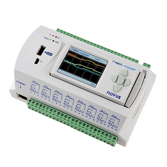
Fig. 12 - FieldLogger front panel FieldLogger has two rows of terminals for diverse connections; among them are the following items: Ethernet, input connections, power supply, output relays, auxiliary power supply output, digital inputs and serial communication. This information is identified in the box of FieldLogger according to Fig. 13 and Fig. 14: Fig. -
Page 11: Power Supply
RELAYS FieldLogger has 2 relays that can be used in the activation of electrical loads (please check the Specifications section). For each relay, we have the common terminal, NC (normally closed) terminal and the NO (normally open) terminal. When deactivated, the relay common is in contact with the NC terminal. When activated, the common is in contact with the NO terminal. -
Page 12: Auxiliary Power Supply For Powering Transmitters
AUXILIARY POWER SUPPLY FOR POWERING TRANSMITTERS For non 24 V models, there is a 24 Vdc power supply available in the FieldLogger for powering transmitters in the field. This auxiliary power supply is electrically isolated from the other FieldLogger terminals. -
Page 13: Analog Inputs
The connection for the channels is made to the terminals in accordance with the figure at the left. The 3-wire connection from the Pt100 sensing element to the FieldLogger input guarantees the cancellation of the error caused by the resistance of the wires. All three wires must have the same gauge and length. -
Page 14: Connectivity Resources
Interface used for Ethernet 10/100 communication. It is recommended to use a category 5 (or better) cable in a RJ45 connector. The Ethernet connector of the FieldLogger has two LEDS for luminous indication: the green LED (on the left side) lights indicating the connection to the Ethernet network; the yellow LED (on the right side) flashes indicating that there is data traffic in the interface. -
Page 15: Flags (Leds)
In error cases, this LED will be flashing 3 times at 8 second intervals. In the error cases, please check if the clock of the FieldLogger has the correct date and time. If they are wrong, probably the battery of the clock has run low and needs to be replaced. -
Page 16: Installing The Usb Driver
WINDOWS 7 1. Connect FieldLogger in a USB port on your computer. Windows will try to install a driver automatically and will not succeed, because the necessary driver is not in its standard library. - Page 17 3. Locate the FieldLogger (probably with an icon with an exclamation mark next to it) and double-click on it. 4. Click on the button "Update Driver...". NOVUS AUTOMATION www.fieldlogger.net 17/104...
- Page 18 5. Ask to "Browse my computer for driver software". 6. Enter the path of the folder where the drivers are located (the product CD or folder where you saved them when downloaded from the site.) 7. Wait for the installation to take start. NOVUS AUTOMATION www.fieldlogger.net 18/104...
- Page 19 8. Windows will indicate that it cannot verify the editor of this driver. Confirm to install anyway! 9. A message indicating successful installation will display. 10. Returning to the Device Manager screen, you can check which virtual serial port is allocated to the FieldLogger. NOVUS AUTOMATION www.fieldlogger.net...
-
Page 20: Definition And Selection Of Serial Port (Com) - Windows
In some cases, the serial ports can be checked as in use even when the associated device is no longer installed on your computer. In this case it is safe to associate this port to FieldLogger. The following figure presents the view of the device manager containing a FieldLogger, and the screens showing the property screens where you can reset the associated COM port. -
Page 21: Configuration And Data Download Software
• Diagnostics: Allows you to read the values of the enabled channels, the status of configured alarms and general information and device status. • Download: Allows you to perform data download of FieldLogger logging memory, view and export them in various formats. -
Page 22: Configuration
If the chosen option was to create a new configuration, you must specify a file where this configuration will be saved. Besides that, from software version 1.40 on, you must select which FieldLogger model you are about to configure (power –... - Page 23 Load Screen Initial Configuration: Undo the changes introduced by the user, returning to the initial configuration of the current screen. • Cancel: Closes the current configuration. • Next: Performs the settings check of the current configuration screen and, if everything is OK, goes to the next screen. Icon toolbar NOVUS AUTOMATION www.fieldlogger.net 23/104...
-
Page 24: General Configurations
The first screen shows some general parameters of configuration for the FieldLogger: • Tag (name) to be given to the equipment (maximum of 16 characters). • When using a HMI with the FieldLogger, please indicate the level of access that the operator will get through the HMI: No HMI access: Prevents the use of the HMI, because no parameter can be viewed by it in this FieldLogger. -
Page 25: Rs485 Interface Configuration
When it is used as a master, it is not necessary to configure the Modbus address (only valid for the slaves). Moreover, in this case, the configuration of Modbus network, where it says which registers are read from what slaves, will be carried through later on, on the Remote Channels screen. Interface RS485 NOVUS AUTOMATION www.fieldlogger.net 25/104... -
Page 26: Ethernet Interface Configuration
The configuration of the Ethernet interface should be carried through on the next screen. If it is desired not to use this interface, it is recommended to disable it, as shown in the following figure. Disabled Ethernet Interface NOVUS AUTOMATION www.fieldlogger.net 26/104... -
Page 27: Ethernet Interface Configuration - Tcp/Ip
Moreover, we must choose whether or not to use DNS, which can be used to connect to the e-mail server or FTP server (when FieldLogger is the FTP client for the daily download of data through this service). If so, you must configure the DNS server's IP number or, if the DHCP option has been selected, you can choose to search for the DNS server’s IP... -
Page 28: Ethernet Interface Configuration - Ftp
FieldLogger: client and server. As a server, FieldLogger allows for an external client to connect to it in order to download logged data, both from the SD card as well as from the internal memory. For this, you must configure the connection and access data, like user name (maximum of 10 characters), password (maximum of 10 characters) and port for the connection. - Page 29 Ethernet Interface - FTP Configuration – Example 2 NOVUS AUTOMATION www.fieldlogger.net 29/104...
-
Page 30: Ethernet Interface Configuration - Smtp
ETHERNET INTERFACE CONFIGURATION - SMTP The SMTP button opens the parameters related to sending e-mails. The FieldLogger allows, in situations of alarm or event, e-mails to be sent to multiple receivers. On this screen, the parameters related to the access to the e-mail server must be configured, such as its IP address or server name (in case you enabled the DNS –... -
Page 31: Ethernet Interface Configuration - Snmp
ETHERNET INTERFACE CONFIGURATION - SNMP The SNMP protocol can be enabled and configured by clicking on the SNMP button. SNMP in the FieldLogger is read- only. Thus, you should set up the community for access (maximum of 16 characters) and connection port. -
Page 32: Ethernet Interface Configuration - Http
ETHERNET INTERFACE CONFIGURATION – HTTP The HTTP button enables FieldLogger to serve a web page with some data from the equipment. This page has an auto- refresh parameter, indicating to the navigator software (browser) that the page should be reloaded with updated data from time to time. -
Page 33: Ethernet Interface Configuration - Modbus Tcp
Ethernet interface has been selected. FieldLogger should be accessed by the “255” identification (ID). Any other ID used in a FieldLogger Modbus-TCP access will be understood as being targeted to a RS485 slave in the RS485 network, reached through the gateway function. -
Page 34: Ethernet Interface Configuration - Cloud
(check digital channels configuration). The writing to this parameters from the Cloud should be enabled in its configuration, as well as the time period that FieldLogger should check if there is any new value to be written. From firmware version 1.64 on, it is possible to schedule a daily reset for the FieldLogger. This is a common practice in routers assuring that, when everything else goes wrong and communication cannot send data anymore, a fresh new start will make things right again. -
Page 35: Analog Channels Configuration
"FieldLogger – Modbus”. • Reading the value of the channel via HMI. • Reading the value of the channel through the HTML page generated by FieldLogger itself (HTTP service on the Ethernet interface). • Reading the value of the channel through the OID reading of SNMP protocol (SNMP service of Ethernet interface). - Page 36 Analog Channels – Configuration of a linear channel NOVUS AUTOMATION www.fieldlogger.net 36/104...
-
Page 37: Analog Channels Configuration - Custom Calibration
The existence of previous points will interfere in the measurements and the new calibration might have errors due to this fact. For the same reason, customized calibration points should be configured in the FiledLogger all at the same time. NOVUS AUTOMATION www.fieldlogger.net 37/104... -
Page 38: Digital Channels Configuration
The counting values can be accessed by Modbus registers (check the document “FieldLogger – Modbus”) and can also be copied to a virtual channel, where it can be logged or used by the alarms, for example. When applying a new configuration in the digital channels, the all previously collected counting values are reset to zero. - Page 39 Digital channels – Configuring an output The two FieldLogger relays are also configured on this screen and their configuration is similar to that of other digital outputs. You should just indicate whether they are triggered by internal alarms or external Modbus commands.
-
Page 40: Remote Channels Configuration
Modbus master. In the case of the RS485 interface having been configured as a slave or disabled, the remote channels screen shall display a message indicating the inability of its configuration. Remote Channels Disabled NOVUS AUTOMATION www.fieldlogger.net 40/104... - Page 41 Places” field (available from firmware version 1.40 on). Configuring one decimal place, for example, will make a value read of “2705” to be considered as “270.5” by the FieldLogger. It must be also informed whether the value being read is signed or unsigned, which depends basically on how the slave puts its information available.
- Page 42 At the bottom of the screen there are the general parameters of the Modbus Master configuration. The reading interval, given in tenths of seconds (maximum 18,000, equivalent to 30 minutes) is the time that you want FieldLogger to make a new scan of all configured remote channels.
-
Page 43: Virtual Channels Configuration
For more details, please see the section "Virtual Channels" under the chapter "FieldLogger Operation”. Clicking on any virtual channel in the list, its parameters are loaded at the top fields. To delete a channel, you must select it from the list and click on "Remove". -
Page 44: Alarms Configuration
"Remove". To modify some parameter of an alarm, you must select it from the list, change whatever you want and click on "Modify". The button "Delete all" deletes all alarms in the list. Alarms Configuration - Relays selection NOVUS AUTOMATION www.fieldlogger.net 44/104... - Page 45 Alarms Configuration - Digital outputs selection Alarms Configuration - Logs control configuration NOVUS AUTOMATION www.fieldlogger.net 45/104...
- Page 46 Alarms Configuration - E-mail receivers selection Alarms Configuration - Enabling SNMP traps NOVUS AUTOMATION www.fieldlogger.net 46/104...
- Page 47 Alarms Configuration – Selection the internal variables Alarms Configuration - Alarm added to the list NOVUS AUTOMATION www.fieldlogger.net 47/104...
-
Page 48: Logs Configuration
In such a case, the logs would have repeated data. • The more logs we have in memory, the slower the download process will be and more data will be processed in preview and export. Logs Configuration – Logging configuration NOVUS AUTOMATION www.fieldlogger.net 48/104... - Page 49 If, instead of sending the configuration to the equipment, you just want to save it to a file, you must choose the file name and click on the “Save” button. NOVUS AUTOMATION www.fieldlogger.net 49/104...
-
Page 50: Diagnostics
Modbus commands is enabled, there are buttons in order to perform the respective actions of starting and stopping the logs. Diagnostics - General Status NOVUS AUTOMATION www.fieldlogger.net 50/104... - Page 51 "Start" button and the channel values will be read every 2 seconds (approximately) and will be plotted on the chart. If any channel is in error, the channel selection will be shown in red. Diagnostics - Monitoring channels NOVUS AUTOMATION www.fieldlogger.net 51/104...
- Page 52 In the list below, the settings for each alarm are shown. If the alarm is active, its configuration is shown in red. Diagnostics - Monitoring Alarms NOVUS AUTOMATION www.fieldlogger.net 52/104...
-
Page 53: Download
The idea is that users shall create a folder on their computer (or their network) where a logging database will be created. This database may have data from one or more FieldLogger’s and will be the destination of all data downloaded from the equipment. -
Page 54: Download Data
This option should be used to process data previously downloaded via FTP. When selecting to download data directly from FieldLogger, a window will pop up asking for the connection mode to the equipment. One of these interfaces can be selected to download data: Ethernet (Modbus TCP) interface, USB (device) interface or RS485 (Modbus RTU) interface. - Page 55 Ethernet/Modbus TCP or RS485/Modbus RTU and there are many FieldLogger’s in the network). Then the FieldLogger memory where logged data is (internal flash or SD card) must be chosen.
-
Page 56: Download Manager
Next step is transferring data from FieldLogger to data base folder. By clicking on the green arrow button in order to proceed, the download of logged data will start and a progress bar will be displayed in order to indicate the download progress. -
Page 57: Using Step-By-Step (Wizard)
First of all, user must choose the way data will be processed. The available ways include viewing in table format, viewing in chart format, export data to a well-known file type and creation of a report with the desired data. In the next screen, the database folder, where all FieldLogger’s have their logging data saved, must be confirmed. NOVUS AUTOMATION www.fieldlogger.net... - Page 58 In the next screen, user must select which FieldLogger data would like to be viewed. Selection is done by their serial number. After that, the desired time period must be selected. NOVUS AUTOMATION www.fieldlogger.net 58/104...
- Page 59 In order to view data in this format, no more than 16 channels can be viewed. NOVUS AUTOMATION www.fieldlogger.net...
- Page 60 In order to view data in this format, no more than 16 channels can be viewed. Viewing logged data in chart format There is a button on the upper left corner that allows users to print the chart. NOVUS AUTOMATION www.fieldlogger.net 60/104...
- Page 61 To export the selected data, you must click on the “Export” button. After a prior processing, a window will appear where you must select the destination folder, the file name and the file extension to be exported. NOVUS AUTOMATION www.fieldlogger.net...
- Page 62 For exporting in “SuperView” or “FieldChart” format, there is a top limit of 16 channels. For exporting in “PDF” or “RTF” format, there is a top limit of 8 channels. Upon completion of the export process, a window is displayed showing its success. NOVUS AUTOMATION www.fieldlogger.net 62/104...
- Page 63 When clicking on the “OK” button, data is processed (a progress bar is showed at the bottom part of the screen) and, when ready, the chart with data from the desired period is viewed. On this moment, some comment lines can be added to be part of the final report. NOVUS AUTOMATION www.fieldlogger.net 63/104...
- Page 64 At the end, clicking on the “OK” button will generate and show the report. This report can be printed or saved to a file for later access. NOVUS AUTOMATION www.fieldlogger.net 64/104...
-
Page 65: Non Step-By-Step
You must choose, through the respective serial number, the equipment that has data of interest at this time. After that, you must define the timCe period of interest and click on "Show available channels". NOVUS AUTOMATION www.fieldlogger.net 65/104... - Page 66 Then, select which channels, among those available, are of interest. Finally, the chosen channels can be viewed in several ways. Viewing logged data in table format NOVUS AUTOMATION www.fieldlogger.net 66/104...
- Page 67 To export the selected data, you must click on the “Export” button. After a prior processing, a window will appear where you must select the destination folder, the file name and the file extension to be exported. NOVUS AUTOMATION www.fieldlogger.net...
- Page 68 Whenever choosing the “Other formats” options, a second window pops up, allowing the choice of the type of the file and many other options. Upon completion of the export process, a window is displayed showing its success. NOVUS AUTOMATION www.fieldlogger.net 68/104...
-
Page 69: Preferences
In order to remove the need of a password to access the equipment, simply leave the new passwords fields blank. This property is available since firmware version 1.40. FieldLogger leaves factory with no passwords set. NOVUS AUTOMATION www.fieldlogger.net... -
Page 70: Command-Line Operation
“4” to get data from a folder. This option should be used when data was already downloaded from the FieldLogger through a USB flash drive, FTP or when reading directly from the device SD card (plugged in your computer). This option requires the folder path as an additional parameter (the folder with the device serial number must be included). -
Page 71: Action Parameters
Number of decimal places to be used for channels values. Valid values: 0 to 6. • Example: “test_report;2;1;” When the chosen Action is “3” (download only, no export), the parameter “NULL” must be used to indicate that no export is needed. Example: “NULL;” NOVUS AUTOMATION www.fieldlogger.net 71/104... -
Page 72: Fieldlogger Operation
The following table outlines what to expect in the indication of FieldLogger depending on the signal applied at the input, for each type of configured input. -
Page 73: Digital Inputs/Outputs
It is important to point out that the insertion of custom calibration points is optional, available only to those who want to adjust the indication with a local standard, because FieldLogger already comes fully calibrated from the factory. -
Page 74: Countings
FieldLogger auxiliary RS485 interface is in the DB9 connector which is located under FieldLogger cover. Its main function is to provide data to FieldLogger HMI, but from firmware version 1.20 on, it can be used as a generic interface, acting as a Modbus-RTU slave. Some futher details can be seen in “HMI (Human-Machine Interface)” section. -
Page 75: Remote Channels
Tx led turns ON. When the slave responds to the command, the Rx led turns ON. This way, during a normal FieldLogger scan of some slaves, Tx and Rx LEDs should flash alternately as many times as the number of the configured remote channels. - Page 76 ByteInv Int32ToFloat when the register read from a slave has a byte order (endianness) which is opposite to the one expected by FieldLogger. (1) Note 1: Available from firmware version 1.10 on. (2) Note 2: Available from firmware version 1.20 on.
-
Page 77: Usb Interface
• Use a USB flash drive with enough space for all data that must be downloaded (preferably an empty USB flash drive). • Depending on the volume of data and the busy rate of the FieldLogger processor, the download may require a long period of time. To optimize data download via USB flash drive, try to download data more frequently and set the Download Period option for a few days, which will reduce the data volume in each download. -
Page 78: Modbus-Tcp
In case of any problems during the start-up of the equipment when sending emails, you can use a Telnet client to view messages that may help you to identify the problem. All you need do is point the Telnet client to the FieldLogger IP address (port 23) and observe the messages posted. -
Page 79: Web Pages - Http
WEB PAGES - HTTP FieldLogger has the capacity to serve web pages. It has three unchangeable and always available pages with basic information about channels, configuration, status and alarms. Besides that, from firmware version 1.30 on, is is capable of serving custom web pages, which are hosted in the SD card. - Page 80 The configuration and status information page has the current status of some parameters, as well as serial number, firmware version and other information from the equipment. Fig. 23 - Configuration and status information HTML page NOVUS AUTOMATION www.fieldlogger.net 80/104...
-
Page 81: Custom Pages
1.10 on. FieldLogger can serve web pages that are hosted in its SD card, since they are located in the “webserv” folder. These pages can use many information directly from FieldLogger, like channels values and units, clock time and serial number. - Page 82 Markers A lot of information from FieldLogger is available to be inserted in the custom web pages. It is done by the use of alphanumeric markers that, when found in the file, are replaced by their related value. Again, this will only happen in the files whose names start with a “_”...
- Page 83 %ALARM__032.CND% Alarm 32 configured condition: “>”, “>=”, “<”, “<=”, “==” or “!=” %ALARM__032.UNI% Alarm 32 configured unit %ALARM__032.HYS% Alarm 32 configured hysteresis %INFO.IN.FLTAG_% FieldLogger tag %INFO.IN.SERIAL% Serial Number %INFO.IN.FWVER_% Firmware version %INFO.IN.MBMODE% Main RS485 interface Modbus mode: "Disabled", "Master" ou "Slave"...
-
Page 84: File Transfer - Ftp
“new line” characters, or “0Dh” and “0Ah” in hexadecimal). Server To use FTP server on FieldLogger, simply enable this feature in the Configurator application and set up a username and password. In this way, the user will have access to the data files for read-only purposes. -
Page 85: Cloud
The time between records must be greater or equal to 1 second, which is the shortest time interval recognized by NOVUS Cloud. It does not matter if the record is in circular memory or full memory; however, we assume that the record should be slower than the system's ability to send data (FieldLogger + network). In laboratory tests, we successfully sent 100 channels, recording and publishing data every 3 seconds. -
Page 86: Operation
In case of any problems during the start-up of the equipment in the cloud, you can use a Telnet client to view messages that may help identify the problem. All you have to do is point the Telnet client to the FieldLogger IP address (port 23) and observe the messages posted. - Page 87 • Immediate start and stop by date/time: As soon as the new configuration is applied, loggings are started. The FieldLogger goes on logging until the arriving of the date and time set. In the case of a power failure, logging is interrupted, returning as soon as power returns.
- Page 88 (bigger than 30 s) intervals. Data download consists of copying the data from the internal memory of FieldLogger or from the card to a computer. This process, when using the configuration software, is guided and assisted. When done via USB flash drive, it is also simple and automatic.
-
Page 89: Alarms
ALARMS 32 alarms are available in each FieldLogger. Each alarm requires you to choose a channel, a condition, a set point and hysteresis. When the alarm condition is met (example: Channel_1 > 45.0 º C), an event is generated for which different actions can be associated. -
Page 90: Data Communication
All the configuration of the equipment, as well as the reading of the data of the inputs, are done via Modbus protocol. In the document "FieldLogger - Modbus.pdf" (in the product CD) is found all the information needed to read data from the input channels without using the Configuration software. -
Page 91: Hmi (Human-Machine Interface)
FieldLogger operation parameters. Fig. 25 – FieldLogger with HMI The HMI is attached to the FieldLogger through a DB9 connector located under its cover. The Fig. 10 and 11 demonstrate how the IHM is connected to FieldLogger. - Page 92 HMI screen is divided into three sections: top bar, main area and bottom bar. Top bar (A) shows the FieldLogger logo and the name of the current screen. Main area (B) shows the information regarded to that screen. Bottom bar (C) shows alarms;...
-
Page 93: Favorites" Screen
Whenever an alarm is active, its number will be displayed in red on this screen. In the left side of the bottom bar an alarm flag will be on as long as any of the FieldLogger enabled alarms are active. -
Page 94: Status" Screen
Parameters that are more on the right “belong” to the previous parameter (more on the left). For example, information about the Ethernet interface is placed in the “Ethernet” level, and that, by its turn, is placed in the “FieldLogger” level. - Page 95 The available parameters of this screen are: FieldLogger: ..................FieldLogger configuration Date ................... Date configuration Time ................... Time configuration Ethernet ..................Ethernet interface configuration DHCP Enable ................. DHCP enabling IP Address ................IP address configuration Subnet Mask ................. Subnet mask configuration Gateway .................
-
Page 96: Equipment Software (Firmware) Update
1. Turn off and unplug all FieldLogger connectors attached to it. 2. Copy the flogger.flb file, which is the binary firmware file of the FieldLogger, into USB flash drive root folder. 3. Insert the USB flash drive into the USB host of the FieldLogger (that must remain off). - Page 97 6. If during the copy (writing) of the firmware of FieldLogger there is some kind of error, this will be indicated by the status led that is to stop flashing periodically and repeatedly showing a pattern of blinking as per the occurred error.
- Page 98 7. Remove the USB flash drive from the USB host of the FieldLogger. FieldLogger should reset itself automatically and may be used normally, now with the new updated firmware. We recommend deleting from the USB flash drive the firmware file (flogger.flb) so that no undesired updates in the future occur.
-
Page 99: Clock Battery Replacement
CLOCK BATTERY REPLACEMENT FieldLogger clock is kept by an internal battery as long as the equipment is not powered by the AC mains power. In case of discharge of this battery, logged dates and times may not represent real values. FieldLogger, whenever detecting such a situation, informs it by continuously flashing the Status led three times in a row (check the Flags (LEDs) section). - Page 100 • Unscrew the four screws located under the enclosure. Remove the back cover, taking care not to remove the circuit board. • After removing the back cover, remove the battery. Avoid touching the circuit board! • Insert the new battery and put back the back cover and its four screws. NOVUS AUTOMATION www.fieldlogger.net 100/104...
-
Page 101: Specifications
Weight: 400 g Housing: ABS+PC Protection: IP20 Analog Inputs: The types of input signals accepted by FieldLogger and their maximum ranges of measurement are selected in the Configuration software and are listed in the following table. INPUT TYPE MEASURING RANGE... - Page 102 • Write Single Register (06h) • Write Multiple Registers (0Fh) Number of simultaneous TCP connections: 10 Number of simultaneous UDP connections: 10 FTP (FieldLogger as a server): Supported mode: passive. Standard: UNIX. Number of simultaneous connections: 1. NOVUS AUTOMATION www.fieldlogger.net...
- Page 103 SMTP (e-mail): Supported authentication mode: AUTH LOGIN. Certifications: CE and UL. NOVUS AUTOMATION www.fieldlogger.net 103/104...
-
Page 104: Safety Information
NOVUS liability under this warranty shall not in any case exceed the cost of correcting defects in the product or of supplying replacement product as herein provided and upon the expiration of the warranty period all such liability shall terminate.
Need help?
Do you have a question about the fieldlogger and is the answer not in the manual?
Questions and answers