
Related Manuals for Alpine mra-d550


Summary of Contents for Alpine mra-d550
-
Page 1: Service Manual
SERVICE MANUAL DIGITAL THEATER AMPLIFIER TO ALPINE Home Page 12 / 04-A 68E37809S01 MRA-D550... - Page 2 <Cautions for Safe Repair Work> The following cautions will prevent accidents in the workplace and will ensure safe products. *The symbols indicate caution is needed to prevent injuries and damage to property. The symbols and their meanings follow. If you ignore this symbol and handle the product incorrectly or unsafely, Warning serious injury or death may result.
-
Page 3: Table Of Contents
MRA-D550 Contents Packing Assembly Parts List Packing Method View Specifications Extension Cable Block Diagram Parts Layout on P.W.Boards and Wiring Diagram 8 to 10 Schematic Diagram 11 to 18 Terminal Voltage of IC/TR 19 to 30 Description of IC Terminal... -
Page 4: Packing Assembly Parts List
MRA-D550 Packing Assembly Parts List Symbol Description Symbol Description Part No. Part No. 15-00938Z01 COVER,TERMINAL %1 103-3 09-02927Z01 ASSY,ATFD-0600-01A 102-1 03-01282Z01 SCR,6TP 4X20 ZB A #1 104 68-00323Z42 O/M AOAM 102-2 03-01280Z01 SCR,CUS 3X12 NN $1 104 68-00323Z43 O/M AOEU... -
Page 5: Specifications
MRA-D550 Specifications Power Output (20Hz/1kHz/10kHz input, 1% T.H.D.) Digital In Mode at H/U input ..................Front ch : 60W Analog In Mode at H/U input ..............Front/Rear/Center ch : 60W Analog In Mode at Changer input ................Front ch : 60W Power Output (20Hz/31.5Hz input, H/U Volume Max(Step 35)) -
Page 6: Extension Cable
MRA-D550 Extension Cable *Always connect the Extension Cable when making checks of voltage and repair. LED P.W.Board CB3001 CB1705 CB1704 CB1402 MAIN P.W.Board (1) 01E37771S01 CB2102 CB2101 (2) 01E37772S01 DSP P.W.Board (3) 01E37773S01 TO CONTENTS - 6 -... -
Page 7: Block Diagram
MRA-D550 Block Diagram Digital AMP TORX193 OPT (H/U) TORX193 OPT (CHG) TC9446 TP2150 LC Filter AD Convertor YSS932 AI-NET (H/U) NJM4580 Speaker TP2150 LC Filter TCD6000 Connector AI-NET (CHG) NJM4580 NJM4052 NJM2100 PCM1802 TC9446 TP2150 LC Filter NAVI Input NJM4580... - Page 8 Parts Layout on P.W.Boards and Wiring Diagram(1/3) MRA-D550 TO CONTENTS Orange Color Pattern:Component Side Pattern NOTE : #1 : For North American Model Only, Blue Color Pattern:Foil Side Pattern $1 : For European Model Only, %1 : For General Foreign Model Only, Others:Common.
- Page 9 Parts Layout on P.W.Boards and Wiring Diagram(2/3) MRA-D550 TO CONTENTS NOTE : #1 : For North American Model Only, $1 : For European Model Only, %1 : For General Foreign Model Only, MAIN P.W.Board (Foil Side View) Others:Common. TP11702 C1104...
- Page 10 Parts Layout on P.W.Boards and Wiring Diagram(3/3) MRA-D550 TO CONTENTS LED P.W.Board (Component Side View) DSP P.W.Board From MAIN P.W.Board (CB1704) (Component Side View) To CB2102 CB3001 CB2102 E2130 E2126 C2145 Q3002 C2234 C2121 R2155 IC2105 IC2102 LD3001 C2238 R2160 R2159...
- Page 11 SD1101 SB05–05CP R1101 560–0.25 Z1101 R1102 BK1608HM102 Z1102 560–0.25 BK1608HM102 Z1103 D1101 BK1608HM102 1PS226 TP10208 R1103 TP10209 TP10210 470–0.25 TP10211 TP10212 DIN1101 DIN,JT–DSA5007–011DB D1102 R1302 1PS226 R1303 C1104 R1304 R1105 R1305 0.1–50V R1306 470–0.25 TP1310 R1333 D1103 C1112 DAP202K #1,$1:N.U. %1:0.1 C1319 Q1101...
- Page 12 IC1404 BA00AST–V5 Q1415 2SB1243 TP1402 TP1405 Z1406 CNF20R102S Q1405 DTC114YKA TP1403 TP1404 IC1408 TP10810 BA00AST-V5 TP10104 Z1403 CNF20R102S Q1412 Q1422 IC1430 DTA114EKA 2SB1238 TDA3664 R1408 100–0.25 D1401 R1409 DAP202K Q1420 100–0.25 D1403 Q1411 DTC144EKA Q1421 11ES2N–TB5 2SC2412K DTC114YKA R1406 ZD1401 TP1410 HZS6B1L IC1409...
- Page 13 R1503 1.8k–F–0.25 R1505 1.8k–F–0.25 R1501 R1507 R1506 TML1501 SPEAKER TERMINAL 10P 10k–F 10k–F C1591 220p–CH R1509 47k–F C1590 220p–CH R1508 47k–F C1565 0.33–100V C1592 C1593 C1594 C1595 R1504 C1527 1000p–CH 1000p–CH 1000p–CH 1000p–CH IC1501 R1560 TCD6000 SD1507 0.33–100V C1504 MURA110T3-X 0.33–100V R1557 E1501...
- Page 14 R1633 E1603 C1680 C1681 C1682 C1683 1000p–CH 1000p–CH 1000p–CH 1000p–CH 47/50 C1644 SD1611 MURA110T3 Q1605 R1690 IRF530N 22–0.25 T1604 L1607 CHOKE E1609 10–100V–105 R1688 Q1601 IRF530N 22–0.25 R1657 6.2–0.25 TP1602 C1619 IC1604 TP2150B-X TP1601 C1641 C1613 C1638 C1625 C1684 C1685 C1686 C1687 1000p–CH...
- Page 15 C1707 C1712 0.022 R1727 4.7k IC1704 MB88385CPF R1721 4.7k R1706 R1720 4.7k 160–0.25 R1731 4.7k R1719 R1728 4.7k 160–0.25 R1703 R1811 160–0.25 XL1702 R1711 4.00MHz 160–0.25 IC1701 TC74VHCT541AFT R1722 4.7k R1757 Q1702 C1716 DTC124EKA C1715 IC1703 TC74LCX541FT C1722 IC1709 TC7SH00FU C1751 R1813 R1818...
- Page 16 C2111 C2109 E2114 E2115 Z2112 R2135 R2146 R2137 C2142 C2105 22k–F 22k–F 4.7/35–BP 330–F 10/16–BP BK1608HM102 E2110 C2107 Z2111 1/50–BP E2116 R2151 R2142 BK1608HM102 R2147 IC2101 22k–F E2112 PCM1802 4.7/35–BP 27k–F 2.7k–F 1/50–BP E2123 Z2110 E2105 4.7/35 4.7/35 BK1608HM102 C2120 F2101 R2141 E2117...
- Page 17 C2210 R2224 0.47 C2224 0.01 IC2203 C2202 R2218 TC9446F R2213 C2219 R2223 TP2129 R2202 R2206 C2235 C2205 R2239 C2243 XL2201 C2236 24.57MHz N.U. C2209 0.01 R2241 C2245 N.U. CB2102 52437–3091 C2223 R2225 0.47 C2222 0.01 R2201 C2203 IC2202 TC9446F-027 R2211 R2205 C2208 R2210...
- Page 18 TP30008 TP30007 TP30006 TP30005 TP30004 TP30003 TP30002 CB3001 TP30001 FH12–10S–0.5SH Q3001 Q3002 Q3003 DTC143XKA DTC143XKA DTC143XKA Q3004 Q3006 Q3008 Q3007 Q3005 DTC143XKA DTC143XKA DTC143XKA DTC143XKA DTC143XKA TO PARTS LIST TO CONTENTS TO P. W. BOARD - 18 -...
-
Page 19: Ref.no. Pin No
MRA-D550 Terminal Voltage of IC/TR Ref.No. Pin No. Voltage Note Ref.No. Pin No. Voltage Note 4.82 pulse pulse IC1201 4.82 3.27 3.26 pulse 4.83 3.26 pulse IC1202 4.83 3.26 3.23 3.25 2.49 3.23 pulse 3.23 pulse 2.66 3.23 pulse 3.25 3.29... - Page 20 MRA-D550 Ref.No. Pin No. Voltage Note Ref.No. Pin No. Voltage Note 5.01 IC1409 3.29 3.26 5.01 IC1410 3.29 3.26 5.01 IC1411 3.26 2.49 2.49 IC1412 pulse pulse IC1301-3 3.23 pulse 13.2 13.2 12.87 IC1420 3.29 3.28 12.87 3.24 IC1421 3.25 3.24...
- Page 21 MRA-D550 Ref.No. Pin No. Voltage Note Ref.No. Pin No. Voltage Note pulse pulse pulse IC1501-3 pulse pulse pulse pulse pulse pulse pulse pulse IC1502 IC1501-2 pulse pulse IC1503-1 pulse pulse pulse pulse pulse pulse pulse +/-1 pulse -21/44 pulse TO SCHEMATIC...
- Page 22 MRA-D550 Ref.No. Pin No. Voltage Note Ref.No. Pin No. Voltage Note IC1602 -32/41 pulse +/-33 pulse +/-1 pulse -30/-17 pulse -30/-17 pulse IC1503-2 +/-1 pulse +/-33 pulse -32/41 pulse +/-1 pulse +/-1 pulse +/-1 pulse -21/44 pulse IC1603-1 +/-1 pulse...
- Page 23 MRA-D550 Ref.No. Pin No. Voltage Note Ref.No. Pin No. Voltage Note +/-1 +/-33 -32/41 -32/41 +/-1 +/-33 +/-1 -30/-17 IC1603-2 +/-1 +/-1 -30/-17 -21/44 +/-1 +/-1 -17.8/16.8 +/-33 -11/0 -32/41 IC1604-2 +/-1 +/-1 +/-1 -21/44 +/-1 IC1604-1 IC1701 +/-1 -21/44...
- Page 24 MRA-D550 Ref.No. Pin No. Voltage Note Ref.No. Pin No. Voltage Note IC1702 IC1705-2 IC1706 IC1703 pulse pulse IC1707-1 IC1704 sine wave sine wave IC1705-1 TO SCHEMATIC TO CONTENTS - 24 -...
-
Page 25: Voltage Note Ref.no. Pin No
MRA-D550 Ref.No. Pin No. Voltage Note Ref.No. Pin No. Voltage Note IC1707-3 IC1708 IC1709 IC1710 IC1707-2 IC1712 IC1713 IC1714 IC1715 pulse IC1717 pulse TO CONTENTS TO SCHEMATIC - 25 -... - Page 26 MRA-D550 Ref.No. Pin No. Voltage Note Ref.No. Pin No. Voltage Note pulse IC1718 pulse IC2104 pulse IC1719 pulse IC2105 pulse IC2101 IC2106 pulse pulse pulse pulse IC2107 pulse IC2102 IC2108 pulse IC2103 TO CONTENTS TO SCHEMATIC - 26 -...
-
Page 27: Gnd Gnd Gnd Gnd
MRA-D550 Ref.No. Pin No. Voltage Note Ref.No. Pin No. Voltage Note pulse pulse pulse IC2109 pulse pulse pulse IC2201 pulse IC2202-2 pulse pulse IC2202-1 pulse pulse TO SCHEMATIC TO CONTENTS - 27 -... -
Page 28: 98 3.6 Pulse G
MRA-D550 Ref.No. Pin No. Voltage Note Ref.No. Pin No. Voltage Note IC2202-3 pulse pulse pulse IC2203-2 pulse pulse IC2203-1 pulse pulse TO CONTENTS TO SCHEMATIC - 28 -... -
Page 29: 9 Sgnd
MRA-D550 Ref.No. Pin No. Voltage Note Ref.No. Pin No. Voltage Note 3.23 Q1101 3.23 IC2203-3 Q1402 pulse pulse Q1403 pulse pulse pulse IC2204 Q1404 pulse IC2205 Q1405 13.2 pulse Q1408 pulse pulse IC2206 Q1409 pulse Q1411 13.2 IC2207 Q1412 13.2 13.2... - Page 30 MRA-D550 Ref.No. Pin No. Voltage Note Ref.No. Pin No. Voltage Note 4.39 Q1501 Q2101 1.74 4.96 4.39 Q1502 Q2102 4.29 4.96 -30/40 pulse Q1504 Q3001 +/-32 pulse -32/-16 pulse Q1505 Q3002 +/-32 pulse -32/-16 pulse Q1506 Q3003 +/-32 pulse -30/40...
-
Page 31: Description Of Ic Terminal
MRA-D550 Description of IC Terminal 70F3033BYGC : IC1707 Symbol Terminal Description RL_ON(NC) No connect terminal. SCL_2 Digital AMP control terminal. 932_SO DSP Decoder control terminal. 932_SI 932_SCK EVDD_33 3.3V connect terminal. EVSS GND connect terminal. 932_CS DSP Decoder control terminal. - Page 32 MRA-D550 Symbol Terminal Description BUS_R/W Ai-NET R/W control terminal. BUS_RS Ai-NET RS control terminal. BUS_SOUT Ai-NET SOUT control terminal. BUS_SIN Ai-NET SIN control terminal. BVDD33 +3.3V connect terminal. BVSS GND connect terminal. BUS_SCLK Ai-NET SCLK control terminal. No connect terminal.
-
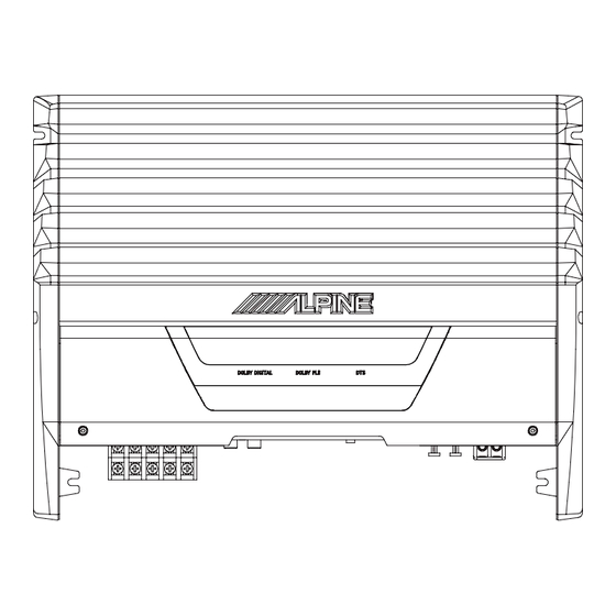
Page 33: Exploded View (Cabinet)
MRA-D550 Exploded View (Cabinet) JK2101 DIN2102 DIN2101 TML1501 IC1202 DIN1101 IC1201 HL1402 CB1102 F1402 F1401 HL1401 TML1401 TO CONTENTS TO PARTS LIST - 33 -...
Need help?
Do you have a question about the mra-d550 and is the answer not in the manual?
Questions and answers