Table of Contents
Advertisement
Quick Links
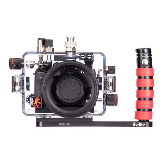
Underwater Housing for Canon EOS M3
Product Number 6973.03
I n s t r u c t i o n M a n u a l
Thank you for your purchase of Ikelite equipment. Please read this
instruction manual completely before attempting to operate or dive
with this product. Please refer to the back page of this manual to
register your Ikelite product.
Advertisement
Table of Contents
Troubleshooting

Related Manuals for Ikelite 6973.03


Summary of Contents for Ikelite 6973.03
- Page 1 Product Number 6973.03 I n s t r u c t i o n M a n u a l Thank you for your purchase of Ikelite equipment. Please read this instruction manual completely before attempting to operate or dive with this product.
-
Page 2: Table Of Contents
STROBE USE and COMPATIBILITY ......P. 15 Strobe Compatibility ............P. 15 Ikelite Housing Conversion Circuitry ......P. 15 Attach Ikelite Sync Cord to the Housing and Strobe ..P. 15 - 16 Attach Ikelite Strobe Arm to the Housing Handle....P. 17 SPARE PARTS ..............P. 18 RECOMMENDED ACCESSORIES ........P. -
Page 3: Preparation
Table of Contents - continued PHOTO TIPS ..............P. 25 TROUBLESHOOTING ............P. 26 - 28 CUSTOMER SUPPORT..........P. 29 LIMITED WARRANTY ............P. 30 RETURNING PRODUCTS FOR SERVICE ....P. 31 PRODUCT REGISTRATION ..........Back Page PREPARATION This product has been water pressure tested at the factory and is depth rated to 200 ft (60 m). -
Page 4: Specifications - No Camera Installed
Controls ........All camera buttons and dials are accessible Buoyancy ......Slightly negative in freshwater Depth Rating......200 ft (60 m) Strobe Connection ....Ikelite Digital TTL ICS-5 5-pin Electrical ..........Bulkhead plus TTL circuitry compatible with ..........current model Ikelite DS-series strobes Use Built-in Flash....Yes, with Fiber Optic Ports only Tray and Handle Weight ..8.7 oz (247 g) -
Page 5: Parts Of The Housing - Front View
Parts of the Housing - Front View M-Fn Button External Strobe Connector & Cap Exp. Comp. Dial Fiber Optic Ports Shutter Front Dial Button Flash Pop-up Switch Lens Port Base Lid Snap Lens Release External Tray Mounts Button... -
Page 6: Parts Of The Housing - Back View
Parts of the Housing - Back View MOVIE MENU INFO 1. Mode Dial MF/LEFT Button 2. Power Button 9. Quick Setting Menu/SET Button 3. Movie Button Flash/RIGHT Button Playback Button Erase/DOWN Button 12. INFO Information Button AE Lock Button 13. MENU Button AF Frame Adjustment ISO/UP Button 14. -
Page 7: Housing And Camera Setup Steps
HOUSING and CAMERA SETUP STEPS STEP 1 - Attach/Remove Tray and Handle Skip STEP 1 if Tray and Spacer are factory installed. One side of the Spacer has an adhesive backing. Remove the Protective Film to adhere the Spacer to the Tray. Using a 9/16”... -
Page 8: Step 2 - Initial Camera Settings
STEP 2 - Initial Camera Settings before placing camera in housing Setup your camera for underwater use and then adjust your settings once underwater. Insert a fully charged camera battery and a SD card. Set Mode Dial to “M” Manual Mode. Set Aperture to f/8 and shutter speed to 1/125th second. -
Page 9: Step 3 - Opening The Housing
STEP 2 - Initial Camera Settings - continued when using a strobe/flash. When recording video or shooting stills without a strobe, AWB can still be used, but for more accurate and consistent colors we recommend setting Custom white balance All other camera functions not mentioned should be set to the user’s preference. - Page 10 STEP 4 - Install Camera/Hotshoe in Housing - continued Diagram A Pull to Remove Mounting Plate Mounting Tray 4. Using a coin or flathead screwdriver (preferred), secure the camera Mounting Tray to the camera tripod mount, Diagram B. Tighten camera firmly to avoid movement on tray.
- Page 11 STEP 4 - Install Camera/Hotshoe in Housing - continued 6. Slide the Hotshoe into the top camera mount until it stops. Hotshoe must be all the way forward in the camera mount to assure a good electrical connection with a strobe, Diagram C, below. Make sure hotshoe cord does not interfere with controls or the housing back when closing the housing.
-
Page 12: Step 5 - Closing The Housing
CAUTION: This housing does not come with a lens port. An optional Mirrorless Lens Port must be properly attached to the housing before submersion in water; see ikelite.com for compatible lens/port combinations. After purchasing an optional port for your lens, reference your port instruction manual for proper installation procedure. -
Page 13: Step 7 - Final Check
STEP 7 - Final Check The clear housing permits instant visual inspection of the camera and sealing surfaces as well as complete monitoring of controls and camera LCD screens. This housing has been factory water pressure tested to 200 ft (60 m). Once the housing is closed, recheck the o-ring seal. -
Page 14: Removing The Camera From The Housing
Removing the Camera from the Housing 1. Thoroughly dry housing. 2. Remove the housing back, see Step 3, Opening the Housing, Page 9. 3. Remove the Hotshoe from the camera mount. 4. Grab the thumbscrew with your thumb and index finger. Slowly and gently pull the camera backward to separate from housing, Diagram D. -
Page 15: Strobe Use And Compatibility
This small compact housing has Ikelite designed and patented Conversion Circuitry built right in. The Conversion Circuitry provides real TTL flash exposure when used with Ikelite DS series strobes. The Circuitry is automatically activated once a DS series strobe is attached to the housing and turned on. - Page 16 Attach Ikelite Sync Cord to the Housing and Strobe - cont. 3. Line up the Sync Cord Pins with the corresponding Bulkhead Receptacles. Gently insert Sync Cord ends into each Bulkhead. Either Cord End may be attached to a component. DO NOT force this installation.
-
Page 17: Attach Ikelite Strobe Arm To The Housing Handle
To attach an Ikelite Arm to your Housing Handle, depress the spring-loaded Handle Push Button until it stops. Gently slide the pronged end of the Ikelite Arm into the hole in the top of the Handle as shown below, Diagram F. -
Page 18: Spare Parts
9104.5 Waterproof bulkhead cap RECOMMENDED ACCESSORIES Mirrorless Interchangeable Lens Ports Visit ikelite.com to select the correct Mirrorless Ports for your lenses. Tray + Dual Handles 9523.64 Attaching an optional Tray + Dual Handles will add stability and gripping point(s) for comfortable use of the housing. -
Page 19: Maintenance
Lubricant Ikelite provides silicone lubricant with the housing. We recommend you use only Ikelite lubricant on Ikelite products. Other brands may cause o-rings to swell and not seal properly. Use only enough lubricant to lightly cover the Port Base O-ring, or lubricate a sticky control. -
Page 20: Maintenance
Housing Maintenance Your Ikelite Digital Housing should be given the same care and attention as your other photographic and video equipment. In addition to normal maintenance, we recommend that the housing be returned to Ikelite periodically to be checked and pressure tested. -
Page 21: Control Maintenance
After a few minutes, operate the push button. If this does not correct the problem, return the housing to Ikelite for maintenance. If you are on a trip and unable to return the housing immediately, a push button may be lubricated by pressing and holding the push button all the way in. - Page 22 To lubricate the control, gently pull on the knob until the stainless steel shaft is exposed. Lightly lubricate the shaft, then move the shaft in and out several times. This will lubricate the x-ring in the Ikelite control gland. This should be done before using the housing after a prolonged storage...
- Page 23 In the unlikely event one of these controls sticks or becomes difficult to operate you can remove the control from the housing and lubricate it, or return the housing to Ikelite for maintenance. To remove the control, Diagram J, page 24, loosen the set screw in the knob (allen wrench required);...
- Page 24 Diagram H Lubricate end of shaft Set screw (allen before reinserting into wrench required) gland Housing Control Shaft Knob O-rings Control Tighten set screw down against this Gland flat area when replacing the knob. Diagram I Lubricate shaft Housing Pull out knob to expose shaft Diagram J Control...
-
Page 25: Photo Tips
PHOTO TIPS The number one rule in underwater photography is to eliminate as much water between the camera and subject as possible. Get as close as you can to the subject, then use the zoom. If you are using flash for still photos, subjects beyond 6 feet (1.8 m) will not have much color regardless of strobe power. -
Page 26: Troubleshooting
If still sticky, see the Control Maintenance section, Page 22 and Diagram H, Page 24. - Return housing to Ikelite for routine maintenance. - Check that the strobe is firing when taking a Image is picture. - Page 27 Place one or two new packs in your housing before each day of diving. - If moisture or water droplets are present around the controls or sealing areas, return the housing to Ikelite for evaluation. - Clean the main housing o-ring and sealing surface of the housing.
- Page 28 - Look for hair, dirt, or foreign debris crossing the o-ring seal. - Reassemble the housing without a camera installed and pressure test or take diving. - Return housing to Ikelite for evaluation. Pictures are too - Use custom (manual) white balance when NOT blue or too green using an external strobe.
-
Page 29: Customer Support
CUSTOMER SUPPORT Please read the troubleshooting section of this instruction manual before contacting Ikelite Customer Support. Ikelite Underwater Systems Service Department 50 West 33rd St. Indianapolis, IN 46208 USA Email: ikelite@ikelite.com Phone: 317-923-4523... -
Page 30: Limited Warranty
This Ikelite product is warranted against any manufacturing defects for a period of one (1) year from the original date of purchase. Defective products should be returned to Ikelite postage paid. Ikelite will, at its sole discretion, repair or replace such products, and will return to customer postage paid. -
Page 31: Returning Products For Service
RETURNING PRODUCTS for SERVICE Ikelite is most interested in performing any service to ensure that all products perform as intended. Evidence of purchase date must be provided to obtain warranty service. No prior authorization is required. You may return directly to Ikelite or through an Ikelite dealer. Please include a brief description of the problem, any relevant email correspondence, and/or instructions on what services are required. -
Page 32: Product Registration
PRODUCT REGISTRATION Please go to ikelite.com to register your Ikelite housing within 15 days of purchase. Ikelite Underwater Systems 50 West 33rd Street Indianapolis, IN 46208 USA ikelite.com © 2015 Ikelite Underwater Systems CANON_EOS_M3_01-1115...
Need help?
Do you have a question about the 6973.03 and is the answer not in the manual?
Questions and answers