Table of Contents
Advertisement
Installation Instructions
PACKAGED GAS / ELECTRIC UNITS
. . . . . . . . . . . . . . . . . . . . . . . . . . . . .
. . . . . . . . . . . . . . . . . . . . . . . . . . . . .
. . . . . . . . . . . . . . . . . . . . . . . . . .
. . . . . . . . . . . . . . . . . . . . . . .
. . . . . . . . . . . . . . . . . . . . . . . . . . . . . . .
. . . . . . . . . . . . . . . . . . . . . . . . . . .
. . . . . . . . . . . . . . . . . . . . . . . . . . . .
. . . . . . . . . . . . . . . . . . . . . . . . . . . . . .
. . . . . . . . . . . . . . . . . . . . . . . . . . . . .
. . . . . . . . . . . . . . . . . . . . . .
. . . . . . . . . . . . . . . . . . . . . . . . . . . .
. . . . . . . . . . . . . . . . . . . . . . . . . . . . . . . . . .
Printed in U.S.A.
PGN3 Series
Single Phase
TABLE OF CONTENTS
Page
. . . . . . . .
2
3
. . . . . . . . . . . . . . .
3
3
3
3
4 -- 5
6
6
. . . . . . . . . . . . . . . . . . . . .
8
8
8
10
. . . . . . . . . . . . . . . . . .
11
12
13
International Comfort Products, LLC
Lewisburg, TN. 37091
. . . . . . . . . . . . . . . . . . . . . . . . . . . . .
. . . . . . . . . . . . . . . . . . . . . . . . . . . . . . . . . . . .
. . . . . . . . . . . . . . . . . . . . . .
. . . . . . . . . . . . . . . . . . . . . . .
. . . . . . . . . . . . . . . . . . . . . . . . . . . . . . . . .
. . . . . . . . . . . . . . . . . . . . . . . . . . . . . . .
. . . . . . . . . . . . . . . . . . . . . . . . . . . . . . . .
. . . . . . . . . . . . . . . . . . . . . . . . . . . . . . . . .
. . . . . . . . . . . . . . . . . . . . . . . . . . . . . . . .
. . . . . . . . . . . . . . . . . . . .
. . . . . . . . . . . . . . . . . . . . . .
462 01 1901 01
. . . . . . . . . . . . . . . . . . .
13
. . . . . . . . . .
13
. . . . . . . . . .
17
19
20
20
20
. . . . . . . . . .
20
20
21
21
.
21
22
. . . . . . . . . . . . . . . . . .
22
22
. . . . . . . . . . . . . . . .
22
26--28
29
01- -28- -08
Advertisement
Table of Contents

Related Manuals for ICP PGN324


Summary of Contents for ICP PGN324
-
Page 1: Table Of Contents
Installation Instructions PGN3 Series Single Phase PACKAGED GAS / ELECTRIC UNITS TABLE OF CONTENTS Page Check for Refrigerant Leaks ....Start--Up Heating & Make Adjustments . -
Page 2: Safe Installation Requirements
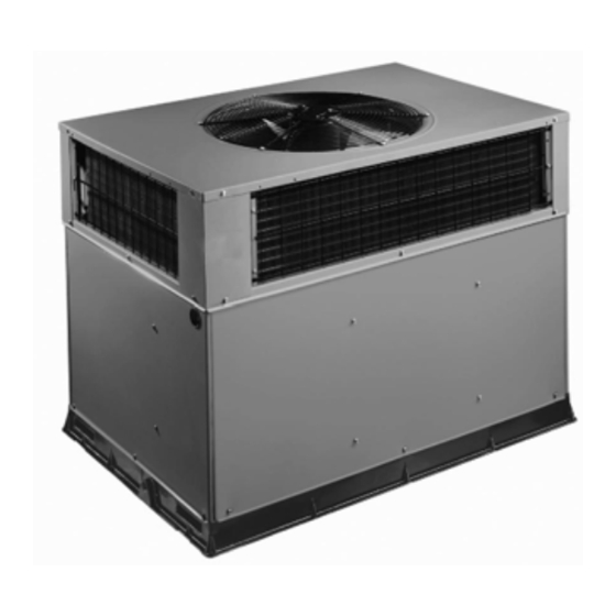
SAFE INSTALLATION REQUIREMENTS FIRE, EXPLOSION, ELECTRICAL SHOCK, CARBON MONOXIDE POISON HAZARD PGN3 GAS / ELECTRIC UNIT FIGURE 1 Failure to follow this warning could result in personal injury, death and/or property damage. Before performing service or maintenance operations on unit, turn off gas supply to unit. Then turn off unit main power switch and install lockout tag. -
Page 3: Introduction
• All connecting ductwork to the unit (supply and return) Curb should be level to within 1/4 in. (6mm) This is must be sealed to the unit casing as specified in section 7. necessary for unit drain to function properly. Refer to •... - Page 4 FIGURE 3 PGN324- -36 DIMENSIONS REQUIRED CLEARANCE TO COMBUSTIBLE MATL. REQUIRED CLEARANCE FOR OPERATION AND SERVICING INCHES [mm] (R efer to M aximum O perating C learances ) EVAP. COIL ACCESS SIDE............36.00 [914.0] INCHES [mm] POWER ENTRY SIDE..............42.00 [1066.8] TOP OF UNIT...................14.00 [355.6] DUCT SIDE OF UNIT.................2.00 [50.8]...
-
Page 5: Dimensions
FIGURE 4 PGN342- -60 DIMENSIONS REQUIRED CLEARANCE TO COMBUSTIBLE MATL. REQUIRED CLEARANCE FOR OPERATION AND SERVICING INCHES [mm] INCHES [mm] EVAP. COIL ACCESS SIDE............36.00 [914.0] TOP OF UNIT...................14.00 [355.6] DUCT SIDE OF UNIT.................2.00 [50.8] POWER ENTRY SIDE..............42.00 [1066.8] SIDE OPPOSITE DUCTS ..............14.00 [355.6] (EXCEPT FOR NEC REQUIREMENTS) UNIT TOP ..................48.00 [1219.2] BOTTOM OF UNIT ................0.50 [12.7]... -
Page 6: Provide Clearances
Table 1—Filter Data- - PGN324- -60 UNIT SIZE 024040 024060 030040 030060 036060 036090 042060 042090 RETURN- -AIR FILTERS (in.)† Throwaway 20x24x1 20x24x1 20x24x1 20x24x1 20x24x1 20x24x1 24x36x1 24x36x1 UNIT SIZE 048090 048115 048130 060090 060115 060130 RETURN- -AIR FILTERS (in.)†... - Page 7 FIGURE 5 Unit Corner Weight (lbs) and Rigging Rigging Brackets are factory installed on 3---phase units only. Single---phase units require accessory kit NPLIFTBK003A10 CORNER WEIGHTS (SMALL CABINET) CORNER WEIGHTS (LARGE CABINET) PGN324 PGN330 PGN336 PGN342 PGN348 PGN360 Unit Unit...
-
Page 8: Connect Condensate Drain
Step 6—Connect Condensate Drain 1. This installation must conform with local building codes and with the National Fuel Gas Code (NFGC), ANSI NOTE: When installing condensate drain connection be Z223.1 (in Canada, CAN/CGA B149.1, and B149.2) or sure to comply with local codes and restrictions. NFPA (National Fire Protection Association) latest revision. - Page 9 Use only pipe dope that is resistant to action of liquefied Sediment Trap FIGURE 7 petroleum gases as specified by local and/or national codes. Never use Teflon tape. 4. Install sediment trap in riser leading to heating section (See Fig. 7). This drip leg functions as a trap for dirt and condensate.
-
Page 10: Install Duct Connections
Step 9—Install Duct Connections Supply and Return Duct Opening FIGURE 8 The unit has duct flanges on the supply-- and return--air openings on the side and bottom of the unit. For downshot applications, the ductwork connects to the roof curb (See Fig. -
Page 11: Install Electrical Connections
Conditioning Contractors National Association The field--supplied disconnect switch box may be mounted (SMACNA) and Air Conditioning Contractors of on the unit over the high--voltage inlet hole when the America (ACCA) minimum installation standards for standard power and low--voltage entry points are used (See heating and air conditioning systems. -
Page 12: Pre--Start--Up
Run the low--voltage leads from the thermostat, through the PRE- -START- -UP inlet hole, and into unit low--voltage splice box. WARNING Locate five 18--gage wires leaving control box. These low--voltage connection leads can be identified by the colors red, green, yellow, brown, and white (See Fig. 10). FIRE, EXPLOSION, ELECTRICAL SHOCK HAZARD Ensure the leads are long enough to be routed into the Failure to follow this warning could result in personal... -
Page 13: Start--Up
5. Charge unit with R--22 refrigerant, using a volumetric WARNING charging cylinder or accurate scale. Refer to unit rating plate for required charge. Be sure to add extra refrigerant to compensate for internal volume of filter FIRE, EXPLOSION HAZARD drier. Failure to follow this warning could result in personal injury, death or property damage. - Page 14 CHECK HEATING CONTROL ADJUST GAS INPUT Start and check the unit for proper heating control operation The gas input to the unit is determined by measuring the gas as follows (see furnace lighting instructions located inside flow at the meter or by measuring the manifold pressure. burner or blower access panel): Measuring the gas flow at the meter is recommended for natural gas units.
- Page 15 1. 32 sec. to complete one revolution. 5. Adjust regulator adjustment screw to the correct manifold pressure, as specified in Table 3. Turn 2. 3600 P 32 = 112.5. adjusting screw clockwise to increase manifold 3. 112.5 x 1 =112.5 ft of gas flow/hr.
- Page 16 FIGURE 14 PGN324- -60 Wiring Diagram...
-
Page 17: Start--Up Cooling & Make Adjustments
LED MONITOR WARNING An LED (light--emitting diode) indicator is provided on the control board to monitor operation. The control board is EXPLOSION AND ENVIRONMENTAL HAZARD located by removing the burner access panel. During Failure to follow this warning could result in personal normal operation, the LED is continuously on (See Table 4 injury, death or property damage. - Page 18 3. Start unit in Cooling Mode and let unit run until system CAUTION pressures stabilize. 4. Measure and record the following: UNIT DAMAGE AND ENVIRONMENTAL HAZARD Outdoor ambient--air temperature (°F(°C)db). Failure to follow this caution may result in unit damage. Suction line temperature (°F(°C)).
-
Page 19: Maintenance
INDOOR AIRFLOW AND AIRFLOW ADJUSTMENTS 3. The set of normally open contacts of energized relay BM close and complete the circuit through evaporator CAUTION blower (indoor) fan motor (IFM). NOTE: Once the compressor has started and then stopped, it should not be started again until 5 minutes have elapsed. UNIT OPERATION HAZARD The cooling cycle remains on until the room temperature Failure to follow this caution may result in unit damage. -
Page 20: Air Filter
minimum maintenance requirements this Loosen setscrew(s) that secures wheel to motor equipment are as follows: shaft, remove screws that secure motor mount brackets to housing, and slide motor and motor 1. Inspect air filter(s) each month. Clean or replace when mount out of housing. -
Page 21: Burner Ignition
BURNER IGNITION Blower Housing and Flue Collector Box FIGURE 15 Unit is equipped with a direct spark ignition 100 percent INDUCED DRAFT MOTOR MOUNT lockout system. Ignition module is located in the control box IGNITION MODULE (See Fig. 15).Module contains a self--diagnostic LED. During servicing, refer to label diagram for LED interpretation. -
Page 22: Outdoor Fan
6. Ensure that setscrew engages the flat area on the Burner Rack Removed FIGURE 18 motor shaft when tightening. 7. Replace grille. ELECTRICAL CONTROLS AND WIRING Inspect and check the electrical controls and wiring annually. Be sure to turn off the electrical power to the unit. Remove access panel to locate all the electrical controls and wiring. - Page 23 Table 7—Dry Coil Air Delivery* - - Horizontal and Downflow Discharge - - Unit PGN324- -060 (Deduct 10% for 208 Volts) Heating External Static Pressure (in. wc) Rise Motor Unit Range Speed (_C) Watts ---------- ---------- Heating Rise ( _ C)
- Page 24 Table 8 Con’t—Dry Coil Air Delivery* - - Horizontal and Downflow Discharge - - Unit PGN324- -060 (Deduct 10% for 208 Volts) Heating External Static Pressure (in. wc) Rise Motor Unit Range Speed (_C) Watts 1242 1170 1089 Heating Rise...
- Page 25 Table 8 Con’t—Dry Coil Air Delivery* - - Horizontal and Downflow Discharge - - Unit PGN324- -060 (Deduct 10% for 208 Volts) Heating External Static Pressure (in. wc) Rise Motor Unit Range Speed (_C) Watts 2027 1960 1901 1821 1759...
- Page 26 Table 9—Troubleshooting Chart SYMPTOM CAUSE REMEDY Power failure Call power company Fuse blown or circuit breaker tripped Replace fuse or reset circuit breaker Defective contactor, transformer, or high--pres- Compressor and condenser fan will not Replace component sure, loss--of--charge or low--pressure switch start.
- Page 27 Table 10—Troubleshooting Guide–Heating SYMPTOM CAUSE REMEDY Water in gas line Drain. Install drip leg. Check power supply fuses, wiring or circuit No power to furnace breaker. Check transformer. NOTE: Some transformers have internal No 20--v power supply to control circuit over--current protection that requires a cool-- down period to reset.
- Page 28 SYMPTOM CAUSE REMEDY Rollout switch will automatically reset, but IGC* will continue to lockout unit. Check gas valve operation. Rollout switch fault Ensure that induced--draft blower wheel is properly Rollout switch has opened. (LED 7 flashes) secured to motor shaft. Inspect heat exchanger. Re- set unit at unit disconnect.
-
Page 29: Start-Up Checklist
START-UP CHECKLIST (Remove and Store in Job File) I. Preliminary Information MODEL NO.:_________________________________ SERIAL NO.:__________________________________ DATE:_______________________________________ TECHNICIAN:_________________________________ II. PRE-START-UP (Insert checkmark in box as each item is completed) ( ) VERIFY THAT ALL PACKING MATERIALS HAVE BEEN REMOVED FROM UNIT ( ) REMOVE ALL SHIPPING HOLD DOWN BOLTS AND BRACKETS PER INSTALLATION INSTRUCTIONS ( ) CHECK ALL ELECTRICAL CONNECTIONS AND TERMINALS FOR TIGHTNESS ( ) CHECK GAS PIPING FOR LEAKS (WHERE APPLICABLE)
Need help?
Do you have a question about the PGN324 and is the answer not in the manual?
Questions and answers