Table of Contents
Advertisement
Advertisement
Table of Contents

Related Manuals for Schenker XMG P504


Summary of Contents for Schenker XMG P504
-
Page 2: Instructions For Care And Operation
Preface Instructions for Care and Operation The notebook computer is quite rugged, but it can be damaged. To prevent this, follow these suggestions: Don’t drop it, or expose it to shock. If the computer falls, the case and the components could be damaged. Do not expose the computer Do not place it on an unstable Do not place anything heavy... -
Page 3: Power Safety
Preface Avoid interference. Keep the computer away from high capacity transformers, electric motors, and other strong mag- netic fields. These can hinder proper performance and damage your data. Take care when using peripheral devices. Removal Warning Use only approved brands of Unplug the power cord before When removing any peripherals. -
Page 4: Battery Precautions
Preface Battery Precautions • Only use batteries designed for this computer. The wrong battery type may explode, leak or damage the computer. • Do not continue to use a battery that has been dropped, or that appears damaged (e.g. bent or twisted) in any way. Even if the computer continues to work with a damaged battery in place, it may cause circuit damage, which may possibly result in fire. -
Page 5: Related Documents
Preface Related Documents You may also need to consult the following manual for additional information: User’s Manual on Disc This describes the notebook PC’s features and the procedures for operating the computer and its ROM-based setup pro- gram. It also describes the installation and operation of the utility programs provided with the notebook PC. System Startup 1. -
Page 6: Specifications
Introduction Specifications Storage Processor Options (Factory Option) One 12.7mm(h) Optical Device Type Intel® Core™ i7 Processor Drive (Super Multi Drive/Blu-Ray Combo Drive/Blu-Ray i7-4930MX (3.00GHz) Writer Drive) 8MB L3 Cache, 22nm, DDR3L-1600MHz, TDP 57W Two Changeable 2.5" (h) SATA (Serial) Hard Disk Drives Intel®... - Page 7 Introduction Audio Communication High Definition Audio Compliant Interface Built-In Gigabit Ethernet LAN S/PDIF Digital Output 2,0M FHD PC Camera Module Two Speakers WLAN/ Bluetooth Half Mini-Card Modules: One Sub Woofer (Factory Option) Intel® Centrino® Ultimate-N 6300 Wire- Built-In Microphone less LAN (802.11a/g/n) Sound Blaster Audio (Factory Option) Intel®...
-
Page 8: External Locator - Top View With Lcd Panel Open
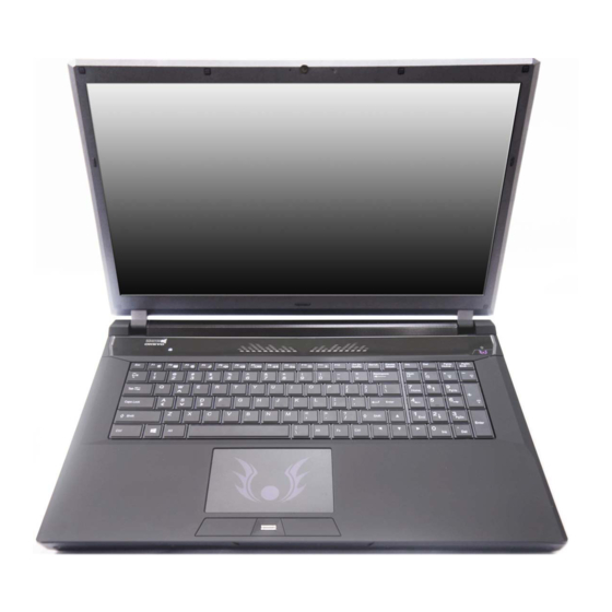
Introduction External Locator - Top View with LCD Panel Open Figure 1 Top View 1. Built-In PC Camera 2. PC Camera LED 3. Built-In Microphone 4. LCD 5. Speakers Note that Illuminated Touchpad has a defined valid 6. LED Indicators operational area of sensitivity 7. -
Page 9: External Locator - Front & Right Side Views
Introduction External Locator - Front & Right side Views Figure 2 Front Views 1. LED Power Indicators Figure 3 Right Side Views 1. Optical Device Drive Bay 2. Emergency Eject Hole 3. Headphone Jack 4. Microphone Jack 5. S/PDIF-Out Jack 6. -
Page 10: External Locator - Left Side & Rear View
Introduction External Locator - Left Side & Rear View Figure 4 Left Side View 1. Mini-IEEE 1394a Port 2. RJ-45 LAN Jack 3. USB 3.0 Port / USB Charge 4. USB 3.0 Port 5. Combined eSATA/ Powered USB 3.0 Port 6. -
Page 11: External Locator - Bottom View
Introduction External Locator - Bottom View Figure 6 Bottom View 1. Sub Woofer 2. Fan Outlet/Intake 3. Component Bay Cover 4. Primary HDD Bay 5. Secondary HDD 6. Battery Overheating To prevent your com- puter from overheating make sure nothing blocks the vent/fan in- takes while the com-... -
Page 12: Maintenance Tools
Disassembly NOTE: All disassembly procedures assume that the system is turned OFF, and disconnected from any power supply (the battery is removed too). Maintenance Tools The following tools are recommended when working on the notebook PC: • M3 Philips-head screwdriver •... -
Page 13: Maintenance Precautions
Disassembly Maintenance Precautions The following precautions are a reminder. To avoid personal injury or damage to the computer while performing a re- moval and/or replacement job, take the following precautions: Power Safety Warning 1. Don't drop it. Perform your repairs and/or upgrades on a stable surface. If the computer falls, the case and other Before you undertake components could be damaged. -
Page 14: Removing The Battery
Disassembly Removing the Battery 1. Turn the computer off, and turn it over. 2. Slide the latch in the direction of the arrow (Figure 1a Figure 1 3. Slide the latch in the direction of the arrow, and hold it in place (Figure 1a Battery Removal 4. -
Page 15: Removing The Hard Disk Drive
Disassembly Removing the Hard Disk Drive Figure 2 HDD Assembly The hard disk drive can be taken out to accommodate other 2.5" serial (SATA) hard disk drives with a height of 9.5mm Removal (h). Follow your operating system’s installation instructions, and install all necessary drivers and utilities (as outlined in Chapter 4 of the User’s Manual) when setting up a new hard disk. - Page 16 Disassembly 4. Slide the HDD assembly in the direction of the arrow (Figure 3c Figure 3 5. Remove the hard disk assembly (Figure 3d HDD Assembly 6. Remove screws & and the insulation plate (Figure 3e Removal (cont’d.) 7. Reverse the process to install a new hard disk (do not forget to replace all the screws and covers). c.
-
Page 17: Hard Disk Size Note (Foam Rubber Insert)
Disassembly Hard Disk Size Note (Foam Rubber Insert) Note that the hard disks pictured on the following pages are all 9.5mm(H) hard disk drives. In some cases 7mm(H) hard disk drives will be installed. Figure 4 Foam Rubber Insert for 7mm(H) HDDs •... -
Page 18: Removing The Ssd
Disassembly Removing the SSD Figure 5 SSD Removal 1. Turn off the computer, and remove the battery (page 2 - 5) and hard disk (page 2 - 2. Remove the screws from the shielding plate (Figure 5a a. Remove the screws. 3. -
Page 19: Removing The Optical (Cd/Dvd) Device
Disassembly Removing the Optical (CD/DVD) Device Figure 6 Optical Device 1. Turn off the computer, and remove the battery (page 2 - Removal 2. Locate the secondary hard disk bay cover and remove screws & (Figure 6a 3. Remove the hard disk bay cover and screw at point (Figure 6b a. - Page 20 Disassembly 6. Carefully pry the bezel off the optical device at point (Figure 7d Figure 7 7. Separate the bezel and the optical device. Optical Device 8. Reverse the process to attach the front bezel with the new optical device at point (Figure 7f).
-
Page 21: Removing The Hard Disk From The Secondary Hdd Bay
Disassembly Removing the Hard Disk from the Secondary HDD Bay Figure 8 Note that the secondary hard disk (if installed) is located under the optical device bay (CD/DVD). Secondary HDD Assembly Removal 1. Turn off the computer, and turn it over, remove the battery (page 2 - 5) and optical device (page 2 -... - Page 22 Disassembly 5. Remove screws and the insulation plate from the hard disk (Figure 9d). Figure 9 Secondary HDD Assembly Removal d. Remove the screws and the insulation plate. 6. Reverse the process to install a new disk (make sure you install the insulation plate). 7.
-
Page 23: Removing The Primary System Memory (Ram)
Disassembly Removing the Primary System Memory (RAM) Figure 10 RAM Module The computer has four memory sockets for 204 pin Small Outline Dual In-line (SO-DIMM) DDR 3L type memory modules Removal (see “Memory” on page 1 - 2 ). The total memory size is automatically detected by the POST routine once you turn on your a. - Page 24 Disassembly 5. Lift the component bay cover off the computer case. The modules will be visible at point (Figure 11d Figure 11 6. Gently pull the two release latches ( ) on the sides of the memory socket(s) in the direction indicated below &...
-
Page 25: Removing The Secondary System Memory (Ram)
Disassembly Removing the Secondary System Memory (RAM) Figure 12 RAM Module Memory Upgrade Process Removal 1. Turn off the computer, and turn it over, remove the battery (page 2 - 5), and component bay cover (page 2 - 14). a. Remove 2. - Page 26 Disassembly 5. Disconnect the keyboard ribbon cable and LED ribbon cable from the locking collar socket & by using Figure 13 a small flat-head screwdriver to pry the locking collar pins away from the base. (Figure 13e). RAM Module 6. Remove the keyboard and the memory sockets &...
-
Page 27: Removing The Wireless Lan Module
Disassembly Removing the Wireless LAN Module Figure 14 Wireless LAN 1. Turn off the computer, remove the battery (page 2 - 5) and the keyboard (page 2 - Module Removal 2. The Wireless LAN module will be visible at point under the keyboard (Figure 14a). -
Page 28: Wireless Lan, Combo, 3G & Lte Module Cables
Disassembly Wireless LAN, Combo, 3G & LTE Module Cables Note that the cables for connecting to the antennae on WLAN, WLAN & Bluetooth Combo, 3G and LTE modules are not labelled. The cables/covers (each cable will have either a black or transparent cable cover) are color coded for iden- tification as outlined in the table below. -
Page 29: Removing The Msata Module
Disassembly Removing the MSATA Module Figure 15 MSATA Module 1. Turn off the computer, remove the battery (page 2 - 5), and component bay cover (page 2 - 14). Removal 2. Locate the module, it is visible at point Figure 15a 3.
Need help?
Do you have a question about the XMG P504 and is the answer not in the manual?
Questions and answers