Table of Contents
Advertisement
Quick Links
Advertisement
Table of Contents

Subscribe to Our Youtube Channel
Related Manuals for Schenker XMG P724


Summary of Contents for Schenker XMG P724
-
Page 2: Instructions For Care And Operation
Preface Instructions for Care and Operation The notebook computer is quite rugged, but it can be damaged. To prevent this, follow these suggestions: Don’t drop it, or expose it to shock. If the computer falls, the case and the components could be damaged. Do not expose the computer Do not place it on an unstable Do not place anything heavy... -
Page 3: Power Safety
Preface Avoid interference. Keep the computer away from high capacity transformers, electric motors, and other strong mag- netic fields. These can hinder proper performance and damage your data. Take care when using peripheral devices. Use only approved brands of Unplug the power cord before peripherals. -
Page 4: Battery Precautions
Preface Battery Precautions • Only use batteries designed for this computer. The wrong battery type may explode, leak or damage the computer. • Do not continue to use a battery that has been dropped, or that appears damaged (e.g. bent or twisted) in any way. Even if the computer continues to work with a damaged battery in place, it may cause circuit damage, which may possibly result in fire. -
Page 5: System Startup
Preface Related Documents You may also need to consult the following manual for additional information: User’s Manual on CD This describes the notebook PC’s features and the procedures for operating the computer and its ROM-based setup pro- gram. It also describes the installation and operation of the utility programs provided with the notebook PC. System Startup 1. -
Page 6: System Specifications
Introduction System Specifications Storage Interface Processor Options Up to Two (Factory Option) Changeable 2.5" Four USB 3.0 Ports (Including one AC/DC Pow- Intel® Core™ i7 Processor (6cm) 9.5mm (h) SATA (Serial) Hard Disk ered USB port) i7-4930MX (3.00GHz) Drives/Solid State Drives (SSD) supporting RAID One eSATA Port (USB 2.0 Port Combined) 8MB L3 Cache, 22nm, DDR3L-1600MHz, TDP level 0/1... - Page 7 Introduction Communication Built-In Giga Base-TX Ethernet LAN 2.0M FHD PC Camera Module WLAN/ Bluetooth Half Mini-Card Modules: (Factory Option) Intel® Centrino® Ultimate-N 6300 Wireless LAN (802.11a/g/n) (Factory Option) Intel® Centrino® Advanced-N 6235 Wireless LAN (802.11a/g/n) + Bluetooth (Factory Option) Intel® Centrino® Wireless-N 2230 Wireless LAN (802.11b/g/n) + Bluetooth (Factory Option) Third-Party Wireless LAN (802.11b/g/n) + Bluetooth 4.0...
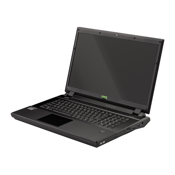
- Page 8 Introduction External Locator - Top View with LCD Panel Open Figure 1 Top View 1. Built-In PC Camera 2. PC Camera LED 3. Built-In Microphone 4. LCD 5. Speakers 6. LED Status Indicators 7. Power Button 8. Keyboard 9. ClickPad and Buttons 10.
- Page 9 Introduction External Locator - Front & Right side Views Figure 2 Front Views 1. LED Power Indicators Figure 3 Right Side Views 1. Optical Device Drive Bay 2. Emergency Eject Hole 3. Combined eSATA/ USB 2.0 Port 4. Powered USB 3.0 Port 5.
- Page 10 Introduction External Locator - Left Side & Rear View Figure 4 Left Side View 1. Security Lock Slot 2. RJ-45 LAN Jack 3. Multi-In-1 Card Reader 4. Line-In Jack 5. S/PDIF-Out Jack 6. Microphone-In Jack 7. Headphone-Out Jack Figure 5 Rear View 1.
- Page 11 Introduction External Locator - Bottom View Figure 6 Bottom View 1. Fan Outlet/Intake 2. Component Bay Cover 3. Sub Woofer 4. Battery 5. HDD Bay Overheating To prevent your com- puter from overheating make sure nothing blocks the vent/fan in- takes while the com- puter is in use.
-
Page 12: Maintenance Tools
Disassembly NOTE: All disassembly procedures assume that the system is turned OFF, and disconnected from any power supply (the battery is removed too). Maintenance Tools The following tools are recommended when working on the notebook PC: • M3 Philips-head screwdriver •... -
Page 13: Maintenance Precautions
Disassembly Maintenance Precautions The following precautions are a reminder. To avoid personal injury or damage to the computer while performing a re- moval and/or replacement job, take the following precautions: Power Safety Warning 1. Don't drop it. Perform your repairs and/or upgrades on a stable surface. If the computer falls, the case and other Before you undertake components could be damaged. -
Page 14: Removing The Battery
Disassembly Removing the Battery Figure 1 Battery Removal If you are confident in undertaking upgrade procedures yourself, for safety reasons it is best to remove the battery. Slide the latch and 1. Turn the computer off, remove the AC/DC adapter and turn it over. hold it in place. - Page 15 Disassembly Removing the Optical (CD/DVD) Device Figure 2 Optical Device 1. Turn off the computer, and turn it over and remove the battery (page 2 - Removal 2. Remove the screw at point , and use a screwdriver to carefully push out the optical device at point 3.
-
Page 16: Removing The Hard Disk Drive
Disassembly Removing the Hard Disk Drive Figure 3 The hard disk drive is mounted in a removable case and can be taken out to accommodate other 2.5" SATA hard disk HDD Assembly drives with a height of 9.5mm (h). Follow your operating system’s installation instructions, and install all necessary driv- Removal ers and utilities (as outlined in Chapter 4 of the User’s Manual) when setting up a new hard disk. - Page 17 Disassembly 5. Remove screws from the hard disk assembly. Figure 4 6. Grip the tab and slide the hard disk assembly in the direction of the arrow (Figure 4e). HDD Assembly 7. Carefully lift the hard disk assembly out of the bay (Figure 4f).
- Page 18 Disassembly Removing the Hard Disk(s) in the Secondary HDD Bay Figure 5 1. Turn off the computer, and turn it over and remove the battery and any HDD in the upper slot. Secondary HDD 2. The secondary hard disk bay is located under the first hard disk. Assembly Removal 3.
-
Page 19: Removing The Keyboard
Disassembly Removing the Keyboard Figure 7 Keyboard 1. Turn off the computer, and turn it over and remove the battery (page 2 - Removal 2. Turn the computer over, open the Lid/LCD, and carefully unsnap up the center cover module from point (between F11 &... - Page 20 Disassembly 9. Push the center cover module down on the left side at point , and then slide the module to the right (as illus- Figure 8 trated) and snap down to secure it in place. Keyboard Removal 10. Replace the screws on the bottom of the computer. (cont’d.) d.
- Page 21 Disassembly Removing the System Memory (RAM) Figure 9 The computer has three memory sockets for 204 pin Small Outline Dual In-line Memory Modules (SO-DIMM) DDR3L RAM-1 Module supporting 1600 MHz. The main memory can be expanded up to 32GB. The total memory size is automatically detected Removal by the POST routine once you turn on your computer.
- Page 22 Disassembly 5. Gently pull the two release latches & on the sides of the memory socket in the direction indicated by Figure 10 the arrows (Figure 10d). RAM-1 Module 6. The RAM module will pop-up, and you can then remove it. Removal (cont’d.) 7.
- Page 23 Disassembly Secondary System Memory Upgrade Process Figure 11 1. Turn off the computer, and turn it over to remove the battery (page 2 - 5), and keyboard (page 2 - 11). RAM-2 Module 2. The RAM module will be visible at point on the mainboard (Figure 11a).
-
Page 24: Removing The Wireless Lan Module
Disassembly Removing the Wireless LAN Module Figure 23 Wireless LAN 1. Turn off the computer, and turn it over, remove the battery (page 2 - 5), keyboard and keyboard shielding plate Module Removal (page 2 - 11). 2. Remove the screw and carefully disconnect cables a.
Need help?
Do you have a question about the XMG P724 and is the answer not in the manual?
Questions and answers