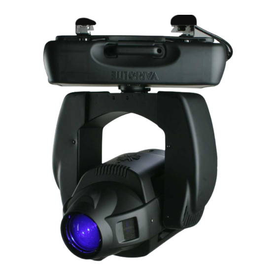
Vari Lite VL2500 SPOT LUMINAIRE Service Manual
Three-wheel cym color mixing
Hide thumbs
Also See for VL2500 SPOT LUMINAIRE:
- Service manual (176 pages) ,
- Service manual (168 pages) ,
- Service manual (138 pages)
Table of Contents
Advertisement
Quick Links
Download this manual
See also:
Service Manual
Advertisement
Table of Contents
Troubleshooting

Related Manuals for Vari Lite VL2500 SPOT LUMINAIRE


Summary of Contents for Vari Lite VL2500 SPOT LUMINAIRE
- Page 1 Vari-Lite is a Philips group brand...
- Page 2 VARI❋LITE® - VL2500™ S UMINAIRE ERVICE ANUAL ® VARI❋LITE is a trademark owned by Philips Group and is registered in the United States and other countries. VL1000™, VL2000™, VL2201™, VL2202™, VL2400™ (and the individual product designations), VL3000™, VL3500™, ™ ™ Series 1000 , Series 2000 ™...
- Page 3 OREWORD How To Obtain Warranty Service A copy of the Vari-Lite, Inc. Limited Warranty was included in the shipping package for this VARI❋LITE® product. To obtain warranty service, please contact customer service at 1-877-VARI-LITE (1-877-827-4548) or customerservice@genlytecontrols.com and request a Return Material Authorization (RMA) for warranty service.
- Page 4 VARI❋LITE® - VL2500™ S UMINAIRE ERVICE ANUAL Compliance Notice This equipment has been tested and found to comply with the limits for a Class A digital device pursuant to Part 15 of FCC Rules. These limits are designed to provide reasonable protection against harmful interference when this equipment is operated in a commercial environment.
- Page 5 OREWORD GENERAL INFORMATION PERTAINING TO PROTECTION AGAINST ELEC- TRICAL SHOCK, FIRE, EXPOSURE TO EXCESSIVE UV RADIATION, AND INJURY TO PERSONS CAN BE FOUND BELOW. WARNING: INSTRUCTIONS FOR CONTINUED PROTECTION AGAINST FIRE 1. VARI❋LITE® luminaires have been designed for use only with certain Philips and Osram HID lamps.
- Page 6 VARI❋LITE® - VL2500™ S UMINAIRE ERVICE ANUAL WARNING: INSTRUCTIONS FOR CONTINUED PROTECTION AGAINST EXCESSIVE EXPOSURE TO UV RADIATION 1. Many VARI❋LITE® luminaires use an HID type lamp that produces UV radiation. DO NOT look directly at lamp. 2. It is hazardous to operate luminaires without lens or shield. Shields, lenses, or ultraviolet screens shall be changed if they have become visibly damaged to such an extent that their effectiveness is impaired.
- Page 7 OREWORD Sicherheitshinweise Es ist äußerst wichtig, ALLE Sicherheitsinformationen und -hinweise in diesem Handbuch und dem beiliegenden Informationsmaterial zu lesen, bevor Sie die hierin beschriebenen Produkte installieren bzw. bedienen. Halten Sie bei der Installation und dem Einsatz dieses Produkts alle Warnhinweise und Vorsichtsmaßnahmen ein. Folgende Sicherheitssymbole werden in diesem Handbuch verwendet: VORSICHT - weist auf möglichen Produktschaden hin.
- Page 8 VARI❋LITE® - VL2500™ S UMINAIRE ERVICE ANUAL 2. Es ist gefährlich, Leuchten ohne Linsen oder Blenden zu bedienen. Blenden, Linsen oder Ultraviolettschirme müssen ausgetauscht werden, sofern deren Schutzwirkung durch sichtbare Beschädigung (z. B. Sprünge oder Schrammen) eingeschränkt ist. WARNUNG: HINWEISE ZUM SCHUTZ GEGEN KÖRPERVERLETZUNGEN 1.
- Page 9 OREWORD Notes de sécurité Avant de procéder à l’installation des produits décrits dans ce guide et de les mettre en marche, il est extrêmement important de lire TOUS les renseignements et TOUTES les directives de sécurité contenues dans ce guide ainsi que toute documentation jointe. Tenir compte de tous les avertissements et suivre toutes les précautions pendant l’installation et l’utilisation de cet appareil.
- Page 10 VARI❋LITE® - VL2500™ S UMINAIRE ERVICE ANUAL AVERTISSEMENT: DIRECTIVES POUR SE PROTÉGER CONTRE UNE EXPOSITION EXCESSIVE AUX RAYONS UV 1. Plusieurs luminaires VARI❋LITE® utilisent une lampe de type HID qui produit des rayons UV. NE PAS fixer son regard sur la lampe. 2.
- Page 11 OREWORD Aviso sobre Seguridad Es muy importante leer TODA la información e instrucciones sobre seguridad que se indica en este manual así como en los documentos adjuntos antes de instalar y operar los productos descritos. Se debe prestar atención a todos los avisos y advertencias durante la instalación y uso de este producto.
- Page 12 VARI❋LITE® - VL2500™ S UMINAIRE ERVICE ANUAL ADVERTENCIA: INSTRUCCIONES PARA PROTECCIÓN CONTINUA CONTRA LA EXPOSICIÓN EXCESIVA DE RADIACIÓN ULTRA VIOLETA 1. Muchas luminarias VARI❋LITE® usan un tipo de lámpara HID que produce radiación UV. NO mire directamente a la lámpara. 2.
- Page 13 AFETY OTICE APANESE 1. VARI❋LITE® Philips Osram MSR400 MSR575HR 4. VARI❋LITE® 1. VARI❋LITE® 2. VARI❋LITE® 02.96 76.002 0 A 01-July-2008 xiii...
- Page 14 VARI❋LITE® - VL2500™ S UMINAIRE ERVICE ANUAL 1. VARI❋LITE® Class A Lamp Power-Up State L ON/ L OFF 01-July-2008 02 .9 676 .00 20 A...
-
Page 15: Table Of Contents
ABLE OF ONTENTS Table of Contents Introduction About This Manual ...................... 1 Additional Documentation................... 1 Customer Service ......................2 Technical Bulletins / Technical Notices............... 2 Chapter 1. Description Features Overview........................4 Features ......................... 4 Major Components External Components....................5 Menu Display ......................6 Menu Controls....................... - Page 16 Chapter 3. Illustrated Parts Breakdown Drawing Tree VL2500 Series Spot Luminaire .................. 42 Top Assembly VL2500 Included Items Kit..................44 VL2500 Spot Luminaire..................... 46 VL2500 Generic Luminaire ..................48 Front Assembly ......................50 Lens Barrel Assembly ....................52 Sub-Barrel Group 2 Assembly ................... 54 Motor Zoom Optics Assembly ...................
- Page 17 ABLE OF ONTENTS Pan EOT Sensor Electrical Assembly................ 98 Ballast Module (Arc Power Supply) Assembly............99 Cables Ground Strap Cable Assembly................. 101 LVS Chassis Ground Cable Assembly..............102 Chassis To Yoke Ground Cable Assembly .............. 103 Yoke To Head Ground Cable Assembly ..............104 Ignitor To Relay Cable Assembly................
- Page 18 VARI❋LITE® - VL2500™ S UMINAIRE ERVICE ANUAL Notes xviii 01-July-2008 02 .9 676 .00 20 A...
-
Page 19: About This Manual
NTRODUCTION Introduction About This Manual This manual provides descriptions, repair procedures, and illustrated parts breakdowns for all configurations of the VL2500™ Spot Luminaire. The manual is intended for use by Vari-Lite personnel and by Vari-Lite’s customers/clients. WARNING: It is important to read ALL accompanying safety and installation instructions to avoid damage to the product and potential injury to yourself or others. -
Page 20: Customer Service
VARI❋LITE® - VL2500™ S UMINAIRE ERVICE ANUAL Customer Service Our Goal At Vari-Lite, we are committed to providing you the highest quality in customer service. Our comprehensive resources are available to help your business succeed and ensure you get the full benefit of being a Vari-Lite customer. Whether your needs are telephone/troubleshooting assistance, product training or technical service, our full- time staff of experienced professionals are on-hand to provide support. -
Page 21: Chapter 1. Description
HAPTER Description This chapter provides an overview of luminaire features, components and operations. • Features • Major Components • Principles of Operation 02.96 76.002 0 A 01-July-2008... -
Page 22: Features Overview
ERVICE ANUAL Features Overview The VL2500 Spot luminaire comes complete with all of the qualities and options designers love from the original Series 2000™ fixtures. It is still small, lightweight, and fast with a 700- watt shortarc lamp, impressive lumen output, and a zoom range from 18.5°... -
Page 23: Major Components
ESCRIPTION AJOR OMPONENTS Major Components External Components The following illustration shows major luminaire components and controls. Truss Hook Bracket Assembly Removable Lamp Assembly (to access lamp for replacement) Upper Enclosure Assembly AC Input Cable Head Assembly Yoke Assembly Vertical Captive Knob Horizontal for lamp access (does not adjust... -
Page 24: Menu Display
VARI❋LITE® - VL2500™ S UMINAIRE ERVICE ANUAL Menu Display The menu system is a programmable set of commands used to configure, address, operate, and test the luminaire. The menu system is controlled at the Menu Display available at the enclosure input panel. Menu Display AC PWR DATA IN... -
Page 25: Head Components
ESCRIPTION AJOR OMPONENTS Head Components The following illustration shows the major sub-assemblies that are located in the luminaire head assembly. (Yoke and enclosure not shown for clarity.) Removable Cover Dual Blade Strobe Assembly Back Cap / CYM Color/Dimmer Bulkhead Lamp Assembly Fixed Color / Fixed Gobo / Iris Bulkhead Fan Assembly... -
Page 26: Yoke Components
VARI❋LITE® - VL2500™ S UMINAIRE ERVICE ANUAL Yoke Components The following illustration shows the major sub-assemblies that are located in the luminaire yoke assembly. (Head and enclosure not shown for clarity.) Yoke Arm Cover Fan Assembly Relay Ignitor PCB Yoke Structure Yoke Arm Cover Tilt-side leg Main Control Board (MCB) -
Page 27: Enclosure Components
ESCRIPTION AJOR OMPONENTS Enclosure Components The following illustration shows the major sub-assemblies that are located in the luminaire enclosure assembly. (Yoke and head assembly not shown for clarity.) Enclosure Top Covers 700W Arc Ballast Module Fan Assembly Input Panel Assembly containing DMX Input PCB and Menu Display 150W +24V/6.3A... -
Page 28: Principles Of Operation
VARI❋LITE® - VL2500™ S UMINAIRE ERVICE ANUAL Principles of Operation Power and Data Flow Diagram The following diagram shows how data and power are distributed in the luminaire. Fix Gobo UV / IR Back Cap OT Sw Switch OT Sw Bulb Ignitor Relay... -
Page 29: Chapter 2. Maintenance
HAPTER Maintenance This chapter contains test, service, and standard maintenance procedures. • Testing • Troubleshooting • Maintenance Procedures 02.96 76.002 0 A 01-July-2008... -
Page 30: Testing
VARI❋LITE® - VL2500™ S UMINAIRE ERVICE ANUAL Testing Testing Software Testing software is available in all Series 2000 luminaires through the luminaire’s menu system TEST function. For information on specific tests and test parameters, see the VL2500™ Spot Luminaire User’s Manual (VL Part no. 02.9676.0019). Note: After 10 seconds of inactivity, the menu display will change to the default state showing the address. -
Page 31: Troubleshooting
AINTENANCE ROUBLESHOOTING Troubleshooting Error Messages If a problem occurs during luminaire calibration, at the end of the calibration sequence the Menu Display will cycle through any applicable error message(s), one at a time until the end of the list is reached. To review the error messages again, it will be necessary to access them “Troubleshooting Guide”... -
Page 32: Troubleshooting Guide
VARI❋LITE® - VL2500™ S UMINAIRE ERVICE ANUAL Troubleshooting Guide If a problem is suspected, try recalibrating the luminaire to prompt an error message. Refer to “Troubleshooting” on page 13 for more information. The chart below provides possible causes and remedies for each message. Table 2-2: Troubleshooting Guide Message Symptom... - Page 33 AINTENANCE ROUBLESHOOTING Table 2-2: Troubleshooting Guide (Continued) Message Symptom Description Possible Cause and Remedy Pan No Luminaire will not pan or Pan Sensor Not Found EOT flag attached to large pulley is not engaging the Sens hits against stop EOT sensor... - ensure flag is attached to the large pulley.
-
Page 34: Maintenance Procedures
VARI❋LITE® - VL2500™ S UMINAIRE ERVICE ANUAL Maintenance Procedures Head Assembly This section provides removal and replacement procedures for components found in the luminaire head assembly. Lamp Replacement Parts: 71.2528.0700 LAMP, 700 WATT SHORT ARC WARNING: Remove power from luminaire before performing maintenance. To replace lamp: Step 1. - Page 35 AINTENANCE AINTENANCE ROCEDURES Note: Wear cotton gloves or other covering while servicing lamp. Touching lamp glass with bare fingers will leave oil and may cause the lamp to explode or reduce lamp life. If required, use alcohol and cotton cloth to thoroughly clean glass portion of lamp.
-
Page 36: Color/Gobo/Iris Bulkhead Replacement
VARI❋LITE® - VL2500™ S UMINAIRE ERVICE ANUAL Color/Gobo/Iris Bulkhead Replacement Parts: 21.9676.4120 ASSY, COLOR/GOBO/IRIS BULKHEAD Procedure: Step 1. Disconnect luminaire AC input cable from power source. Step 2. At top head cover, gradually loosen two 8-32x3/8" captive screws and remove cover. (Cover remains attached by tether.) Figure 2-3. -
Page 37: Standard Gobo/Color Filter Replacement
AINTENANCE AINTENANCE ROCEDURES Standard Gobo/Color Filter Replacement ❋ WARNING: Users of VARI LITE luminaires should not install or use metal gobos. The ❋ use of metal gobos in any VARI LITE product may damage the luminaire and could void the luminaire’s warranty. -
Page 38: Strobe Bulkhead Replacement
VARI❋LITE® - VL2500™ S UMINAIRE ERVICE ANUAL Strobe Bulkhead Replacement Parts: 22.9676.0016 ASSY, STROBE BULKHEAD Procedure: Step 1. Disconnect luminaire AC input cable from power source. Step 2. At head cover, loosen two captive screws and remove cover. (The cover is attached by tether.) Figure 2-5. -
Page 39: Front Assembly Removal
AINTENANCE AINTENANCE ROCEDURES Front Assembly Removal This procedure may be necessary to gain access to other components. To remove and re-install front assembly: Step 1. Disconnect luminaire AC input cable from power source. Step 2. At head cover, turn two captive screws one-quarter turn and remove cover. (It will remain attached by tether.) Figure 2-6. -
Page 40: Rotating Gobo Sensor Pcb Replacement
VARI❋LITE® - VL2500™ S UMINAIRE ERVICE ANUAL Step 8. Re-install front assembly by performing Steps 2–6 in reverse order. While re-installing, first connect wiring harness connection to rotating gobo wheel sensor and route wires through corner between head assembly and bulkhead (ensuring no wires are pinched). - Page 41 AINTENANCE AINTENANCE ROCEDURES CAUTION: Always use anti-static precautions when working with PCBs. Step 4. Remove rotating gobo sensor PCB by removing two 4-40×1/4” PFZ screws. Figure 2-8. 4-40×1/4” PFZ Screws Rotating Gobo Sensor PCB Figure 2-8: Rotating Gobo Sensor PCB Replacement Step 5.
-
Page 42: Edge Motor Assembly Replacement
VARI❋LITE® - VL2500™ S UMINAIRE ERVICE ANUAL Edge Motor Assembly Replacement Parts: 21.9667.0310 ASSY, MOTOR EDGE To remove and replace edge motor assembly: Step 1. Disconnect luminaire AC input cable from power source. Step 2. Remove front assembly. Refer to “Front Assembly Removal”... - Page 43 AINTENANCE AINTENANCE ROCEDURES CAUTION: Ensure you place pliers on standoff on edge motor shaft. Do not hold edge motor shaft with pliers, or shaft may be damaged. Step 5. At lens barrel assembly, use pliers to hold standoff on edge motor shaft, and using 1/4"...
- Page 44 VARI❋LITE® - VL2500™ S UMINAIRE ERVICE ANUAL Step 7. Remove two 4-40×3/8" PPZ screws and nuts which secure motor to bulkhead and remove motor assembly. Figure 2-12. Edge Motor Assembly 4-40×3/8" PPZ Screw (2) 1/4" Nut Figure 2-12: Edge Motor Assembly Replacement Step 8.
-
Page 45: Lens Barrel Assembly Replacement
AINTENANCE AINTENANCE ROCEDURES Lens Barrel Assembly Replacement Parts: 21.9676.4306 ASSY, LENS BARREL To remove and replace lens barrel assembly: Step 1. Disconnect luminaire AC input cable from power source. Step 2. At head cover, turn two captive screws one-quarter turn and remove cover. (It will remain attached by tether.) Figure 2-6. - Page 46 VARI❋LITE® - VL2500™ S UMINAIRE ERVICE ANUAL Step 7. At front of optical support ring, remove three 8-32×3/8" PPZ screws. Figure 2-14. Guide Rod #6 Flat Washer 6-32×1/2" PPZ Screw Lens Barrel Assembly Optical Support Ring 8-32×3/8" PPZ Screw Figure 2-14: Lens Barrel Assembly Replacement Step 8.
-
Page 47: Yoke Assembly
AINTENANCE AINTENANCE ROCEDURES Yoke Assembly This section provides removal and replacement procedures for components found in the luminaire yoke assembly. Tilt Motor Assembly Replacement Parts: 22.9676.0610 ASSY, TILT MOTOR To replace tilt motor assembly: Step 1. Disconnect luminaire AC input cable from power source. Step 2. -
Page 48: Main Control Board (Mcb) Pcb Replacement
VARI❋LITE® - VL2500™ S UMINAIRE ERVICE ANUAL Main Control Board (MCB) PCB Replacement Parts: 24.9676.3730 MCB PCB ASSY To replace an MCB PCB: Step 1. Disconnect luminaire AC input cable from power source. Step 2. At board-side leg, remove yoke leg cover by removing four 6-32×5/16" PPB screws. -
Page 49: Ignitor Pcb Replacement
AINTENANCE AINTENANCE ROCEDURES Ignitor PCB Replacement Parts: 24.9661.1126 PCB ASSY, SOLID STATE IGNITOR To replace ignitor PCB: Step 1. Disconnect luminaire AC input cable from power source. Ignitor PCB Screws Yoke Leg Cover Yoke cross member Figure 2-17: Ignitor PCB Replacement Step 2. - Page 50 VARI❋LITE® - VL2500™ S UMINAIRE ERVICE ANUAL Step 8. Remove two 1/4" hex standoffs from ignitor PCB by removing one 6-32×5/ 16" PPZ screw and #6 lock washer. Install in same place on new ignitor PCB. Figure 2-18. 6-32×5/16" PPZ Screw #6 Lock Washer 1/4"...
-
Page 51: Enclosure Assembly
AINTENANCE AINTENANCE ROCEDURES Enclosure Assembly This section provides removal and replacement procedures for components found in the luminaire enclosure assembly. Removing Enclosure Covers To gain access to enclosure components, it will be necessary to remove the top and bottom covers. To remove and replace enclosure covers: Step 1. - Page 52 VARI❋LITE® - VL2500™ S UMINAIRE ERVICE ANUAL CAUTION: Be careful not to damage lens during next step. Step 4. Carefully lay luminaire on its side, ensuring that lens does not come into contact with any surface. Figure 2-20. Figure 2-20: Laying Luminaire on Its Side Step 5.
-
Page 53: Ballast Module Assembly Replacement
AINTENANCE AINTENANCE ROCEDURES Ballast Module Assembly Replacement Parts: 69.9676.0700 ASSY, BALLAST MODULE, 700W ARC To remove the ballast module assembly: Step 1. Disconnect luminaire AC input cable from power source. Step 2. At enclosure, remove ballast-side and ventilation covers. Refer to “Removing Enclosure Covers”... - Page 54 VARI❋LITE® - VL2500™ S UMINAIRE ERVICE ANUAL Step 6. At ballast, disconnect wiring: Note: Some components not shown for clarity. Ballast Module 8-32×3/8” PFZ Screw (4) 8-32x3/8" PPZ Screws (4) Figure 2-22: Ballast Module Assembly Replacement Step 7. At bottom of enclosure, remove four 8-32×3/8" PFZ screws and four 8/32x3/ 8"...
-
Page 55: Pan Motor Assembly Replacement
AINTENANCE AINTENANCE ROCEDURES Pan Motor Assembly Replacement Parts: 21.9678.0864 PAN MOTOR ASSY Procedure: Step 1. Disconnect luminaire AC input cable from power source. Step 2. Carefully lay luminaire on its side to have access to bottom of enclosure. Step 3. At enclosure assembly, remove bottom cover. Step 4. -
Page 56: Pan Encoder Replacement
VARI❋LITE® - VL2500™ S UMINAIRE ERVICE ANUAL Pan Encoder Replacement Parts: 24.9678.9729 PAN ENCODER Procedure: Step 1. Disconnect luminaire AC input cable from power source. Step 2. Carefully lay luminaire on its side to have access to bottom of enclosure. Step 3. -
Page 57: Pan Eot Sensor Replacement
AINTENANCE AINTENANCE ROCEDURES Pan EOT Sensor Replacement Parts: 86.7002.0003 PAN EOT SENSOR ASSY Repair Procedure Step 1. Disconnect luminaire AC input cable from power source. Step 2. Carefully lay luminaire on its side. Step 3. At enclosure assembly, remove bottom cover. Step 4. -
Page 58: Power Supply (Lvs) Replacement
VARI❋LITE® - VL2500™ S UMINAIRE ERVICE ANUAL Power Supply (LVS) Replacement Parts: 69.3177.0151 POWER SUPPLY (LVS) ASSY Repair Procedure Step 1. Disconnect luminaire AC input cable from power source. Step 2. At enclosure, remove top cover at power supply side. Step 3. -
Page 59: Chapter 3. Illustrated Parts Breakdown
HAPTER Illustrated Parts Breakdown This chapter contains illustrated parts breakdowns for assemblies in the VL2500™ Spot Luminaire. • Drawing Tree • Top Assembly • Yoke • Enclosure • Cables 02.96 76.002 0 A 01-July-2008... -
Page 60: Drawing Tree
VARI❋LITE® - VL2500™ S UMINAIRE ERVICE ANUAL Drawing Tree VL2500 Series Spot Luminaire VL2500 Spot Luminaire 20.9676.0001 Rev K VL2500 Generic Luminaire Front Assembly 21.9676.0010 Rev J 21.9676.4006 Rev E Rotating Gobo Wheel Assembly Upper Enclosure Assembly 21.9660.0105 Rev E 21.9676.0800 Rev S... - Page 61 LLUSTRATED ARTS REAKDOWN RAWING Drawing Tree (continued) Continued from previous page VL2500 Spot Luminaire (continued) Upper Enclosure Assembly 21.9676.0800 Rev S Reflector Assembly Connector Panel Assembly Connector Panel Assembly 22.9676.0018 Rev B 21.9678.0805 Rev L 21.9678.0805 Rev L Fan Assembly...
-
Page 62: Top Assembly
VARI❋LITE® - VL2500™ S UMINAIRE ERVICE ANUAL Top Assembly VL2500 Included Items Kit 28.9676.0001 Rev F Refer to Figure 3-1. Item Qty. Description 02.8001.0001 PRODUCT SUPPORT SHEET, VARI-LITE CUSTOMER SERVICE 02.8052.0001 CARD, LIMITED WARRANTY 02.80001.0002 VARI-LITE QUALITY ASSURANCE CERTIFICATE (not shown) 02.8406.0001 TAG, LAMP NOTICE 02.8700.0001... - Page 63 LLUSTRATED ARTS REAKDOWN SSEMBLY Figure 3-1: Included Items Kit 02.96 76.002 0 A 01-July-2008...
-
Page 64: Vl2500 Spot Luminaire
VARI❋LITE® - VL2500™ S UMINAIRE ERVICE ANUAL VL2500 Spot Luminaire 20.9676.0001 Rev K Refer to Figure 3-2. Item Qty. Description 10.9638.0052 DAM, AIR, VL6 10.9676.8632 COVER, YOKE THERMOFORM 16.9676.0004.01 LABEL LOCATION, VL2500 LUMINAIRE (not shown) 21.9676.0023 ASSY, FRONT COVER 21.9676.4006 ASSY, FRONT 21.9676.0010... - Page 65 LLUSTRATED ARTS REAKDOWN SSEMBLY (x6) (x2) (x4) (x4) Note: Loop lamp wires through ferrite. (x4) (x2) (x8) (x2) Figure 3-2: Top Assembly 02.96 76.002 0 A 01-July-2008...
-
Page 66: Vl2500 Generic Luminaire
VARI❋LITE® - VL2500™ S UMINAIRE ERVICE ANUAL VL2500 Generic Luminaire 21.9676.0010 Rev J Refer to Figure 3-3. Item Qty. Description 10.9628.0211 STABLIZER, PAN/TILT 10.9676.8617 HEATSHIELD, YOKE CROSSMEMBER 10.9676.0083 BAFFLE, REAR CASTING 10.9676.0163 HARNESS, GUARD, RIGHT 10.9676.0161 HARNESS, GUARD, LEFT 21.9676.0139 ASSY, REAR HEAD 21.9676.0600 ASSY, YOKE... - Page 67 LLUSTRATED ARTS REAKDOWN SSEMBLY VL2500 Generic Luminaire (continued) (x8) (x8) (x2) (x2) (x2) (x5) (x5) (x5) (x4) (x4) (x4) (x4) Figure 3-3: VL2500 Generic Luminaire Assembly 02.96 76.002 0 A 01-July-2008...
-
Page 68: Front Assembly
VARI❋LITE® - VL2500™ S UMINAIRE ERVICE ANUAL Front Assembly 21.9676.4006 Rev F Refer to Figure 3-4. Item Qty. Description 10.9660.0129 SHAFT STOP, ROTATING GOBO WHEEL 10.9660.0130 SHAFT, ROTATING GOBO WHEEL 10.9660.0219 SHAFT 1, FOCUS BEARING 10.9676.4255 SHAFT, SUPPORT, LENS 10.9660.0263 SUPPORT, LENS 10.9667.0313 SUPPORT, LENS, CABLE MOUNT... - Page 69 LLUSTRATED ARTS REAKDOWN SSEMBLY Item Qty. Description 55.6506.0009 SPACER, 1/2" RND .125" LG .375" ID SHAFT 55.6589.0003 STANDOFF, 1/4" RND 4-40 .606" LG MF 55.6663.0007 STANDOFF, 3/8" RND, 1.75" LG, FF (x2) (x2) (x2) (x2) (x4) (x2) (x2) (x2) (x2) (x4) (x2) (x2)
-
Page 70: Lens Barrel Assembly
VARI❋LITE® - VL2500™ S UMINAIRE ERVICE ANUAL Lens Barrel Assembly 21.9676.4306 Rev D Refer to Figure 3-5. Item Qty. Description 10.9676.4254 SHAFT, ZOOM BEARING 10.9676.4256 WEAR STRIP, EDGE LENSES 10.9676.4258 WEAR STRIP, EDGE BARREL 10.9676.4259 WEAR STRIP, ZOOM BALL PLUNGER 10.9676.4260 WEAR STRIP BUMPER, EDGE LENSES 12.9676.4248... - Page 71 LLUSTRATED ARTS REAKDOWN SSEMBLY Lens Barrel Assembly (continued) 17 (x4) 14 (x2) 22 (x2) 18 (x2) 16 (x2) 23 (x2) 15 (x4) 19 (x2) Figure 3-5: Lens Barrel Assembly 02.96 76.002 0 A 01-July-2008...
-
Page 72: Sub-Barrel Group 2 Assembly
VARI❋LITE® - VL2500™ S UMINAIRE ERVICE ANUAL Sub-Barrel Group 2 Assembly 21.9676.4229 Rev B Refer to Figure 3-6. Item Qty. Description 10.9676.4223 BARREL, ZOOM, LOWER 10.9676.4250 SPACER 1, ZOOM LENSES 10.9676.4251 SPACER 2, ZOOM LENSES 12.9676.4224 BARREL, ZOOM, UPPER 21.9676.4258 ASSY, ZOOM BUSHING 42.9660.0023 LENS 6, ZOOM OPTICS... -
Page 73: Motor Zoom Optics Assembly
LLUSTRATED ARTS REAKDOWN SSEMBLY Motor Zoom Optics Assembly 21.9667.0311 Rev A Refer to Figure 3-7. Item Qty. Description 44.9660.0262 MOTOR, 1" LINEAR - ZOOM 52.6579.0005 CONN, 5CIR PNL MT SGL ROW W/MTG EARS 52.8347.0001 CONTACT, 24-30AWG MALE CRIMP Figure 3-7: Motor Zoom Optics Assembly 02.96 76.002 0 A 01-July-2008... -
Page 74: Rotating Gobo Wheel Assembly
VARI❋LITE® - VL2500™ S UMINAIRE ERVICE ANUAL Rotating Gobo Wheel Assembly 21.9660.0105 Rev E Refer to Figure 3-8. Item Qty. Description 10.9660.0110 GOBO CARRIER, SPINNING GOBO WHEEL 10.9660.0112 SUN GEAR, SPINNING GOBO WHEEL 10.9660.0144 SPRING GOBO RETAINER, SPINNING GOBO WHEEL 10.9660.0153 MAGNET, HALL EFFECT SENSOR .07ID 10.9667.0333... - Page 75 LLUSTRATED ARTS REAKDOWN SSEMBLY Rotating Gobo Wheel Assembly (continued) 16 (2) 15 (3) 15 (6) Standard Gobos Figure 3-8: Rotating Gobo Wheel Assembly 02.96 76.002 0 A 01-July-2008...
-
Page 76: Sensor Rotating Gobo Pcb Assembly
VARI❋LITE® - VL2500™ S UMINAIRE ERVICE ANUAL Sensor Rotating Gobo PCB Assembly 24.9667.1321 Rev - Refer to Figure 3-9. Replace as a complete assembly. Figure 3-9: Sensor Rotating Gobo PCB Assembly 01-July-2008 02 .9 676 .00 20 A... -
Page 77: Top Cover Assembly
LLUSTRATED ARTS REAKDOWN SSEMBLY Top Cover Assembly 22.9676.0008 Rev H Refer to Figure 3-10. Item Qty. UM. Description 06.6018.0011 0.041 VELCRO, DOUBLE HOOK, 2" BLACK ADH BACKED 07.5049.0001 LANYARD, NYLON COATED, 8" LONG 10.9676.8009 COVER, TOP VL2500 10.9676.0010 FILTER, TOP HEAD COVER 12.9676.0076 BAFFLE, RIGHT, TOP COVER 12.9676.0077... -
Page 78: Bottom Cover Assembly
VARI❋LITE® - VL2500™ S UMINAIRE ERVICE ANUAL Bottom Cover Assembly 22.9676.0011 Rev D Refer to Figure 3-11. Item Qty. UM. Description 10.9676.8012 COVER, LOWER 53.2008.0008 NUT, #8 PUSH 53.6545.0001 SCREW, 8-32 X 3/8" PPB 53.6599.0001 WASHER, #10 FLAT BLACK (x3) (x3) (x3) Figure 3-11: Bottom Cover Assembly... -
Page 79: Reflector Assembly
LLUSTRATED ARTS REAKDOWN SSEMBLY Reflector Assembly 22.9676.0018 Rev B Refer to Figure 3-12. Item Qty. UM. Description 10.9678.0647 CLAMP, MOUNTING, REFLECTOR 22.9660.0338 ASSY, DISCONNECT LAMP 22.9676.0130 ASSY, REFLECTOR MOUNT 41.9660.7021 ELLIPSOIDAL REFLECTOR, LUNED 53.6599.0001 SCREW, 4-40 X 3/8" PFZ 55.6669.0016 STANDOFF, 1/4"... -
Page 80: Back Cap Assembly
VARI❋LITE® - VL2500™ S UMINAIRE ERVICE ANUAL Back Cap Assembly 22.9676.0115 Rev E Refer to Figure 3-13. Item Qty. Description 10.9638.0117 KNOB, KNURLED, VL6 BACK CAP/LAMP ASSY. 10.9638.0128 BRACKET, IGNITOR CABLE 10.9638.0130 SPRING, BULB WIRE SHEATH 10.9638.0164 WASHER, FELT 10.9667.0411 LAMP CARRIAGE 10.9667.0412 LAMP TILT PLATE... - Page 81 LLUSTRATED ARTS REAKDOWN SSEMBLY Back Cap Assembly (continued) (x2) 30(x2) (x2) (x2) (x2) (x2) (x2) (x4) (x2) (x2) (13.5") (x2) (9.0") Figure 3-13: Back Cap Assembly 02.96 76.002 0 A 01-July-2008...
-
Page 82: Fan Assembly
VARI❋LITE® - VL2500™ S UMINAIRE ERVICE ANUAL Fan Assembly 22.9676.0090 Rev D Refer to Figure 3-14. Item Qty. Description 10.9676.0068 AIR DUCT, FRONT FAN 22.9676.0091 ASSY, FAN BULKHEAD 22.9676.0095 AIR DUCT, REAR FAN 25.8007.2212 CABLE ASSY, GROUND STRAP, #6 RING 3" LG 40.7113.0002 FAN, +24 VOLT, 80 X 80 X 25MM, 39CFM 40.7146.0002... - Page 83 LLUSTRATED ARTS REAKDOWN SSEMBLY Fan Assembly (continued) (x2) (x3) (x2) 7, 8 (x5) Figure 3-14: Fan Assembly 02.96 76.002 0 A 01-July-2008...
-
Page 84: Iris/Color/Gobo Bulkhead Assembly
VARI❋LITE® - VL2500™ S UMINAIRE ERVICE ANUAL Iris/Color/Gobo Bulkhead Assembly 21.9676.4120 Rev C Refer to Figure 3-15. Item Qty. Description 10.9676.4124 BULKHEAD, IRIS/GOBO/COLOR 21.9676.0118 ASSY, IRIS/GOBO MOTOR 21.9676.0119 ASSY, COLOR MOTOR 22.9676.4146 ASSY, GOBO WHEEL 22.9676.4145 ASSY, COLOR FILTER WHEEL 22.9676.1145 IRIS, 53MM OD, CUSTOM 25.9676.0125... - Page 85 LLUSTRATED ARTS REAKDOWN SSEMBLY Iris/Color/Gobo Bulkhead Assembly (continued) (x3) (x3) (x3) (x2) (x7) Figure 3-15: Iris/Color/Gobo Bulkhead Assembly 02.96 76.002 0 A 01-July-2008...
-
Page 86: Crossfade Color Assembly
VARI❋LITE® - VL2500™ S UMINAIRE ERVICE ANUAL Crossfade Color Assembly 21.9676.0201 Rev N Refer to Figure 3-16. Item Qty. Description 10.9676.0230.01 SPACER, COLOR WHEEL 10.9676.0230.02 SPACER, COLOR MOTOR 10.9676.0234 AFT BULKHEAD, CROSSFADE COLOR SYSTEM 10.9676.0238 BULKHEAD SPACER 2, COLOR SYSTEM 10.9676.0235 SPACER, BULKHEAD, COLOR SYSTEM 10.9676.0284... - Page 87 LLUSTRATED ARTS REAKDOWN SSEMBLY Crossfade Color Assembly (continued) (x4) (x2) (x2) (x4) (x5) (x4) (x4) (x2) Yellow Cyan Cyan (x2) Magenta Dimmer (x4) (x2) (x6) (x5) Yellow Dimmer Cyan Magenta Figure 3-16: Crossfade Color Assembly 02.96 76.002 0 A 01-July-2008...
-
Page 88: Iris/Gobo Motor Assembly
VARI❋LITE® - VL2500™ S UMINAIRE ERVICE ANUAL Iris/Gobo Motor Assembly 21.9676.0118 Rev D Refer to Figure 3-17. Item Qty. Description 10.9621.0097 STABILIZER, STEPPER, GOBO WHEEL 10.9667.1111 MOTOR BULKHEAD, IRIS/GOBO 10.9667.0126 IRIS CRANK 24.9676.1114 PCB ASSY, SENSOR, VL6B 44.9676.0116 MOTOR, GOBO/COLOR WHEEL 44.9676.0118 MOTOR, IRIS 53.6578.0001... -
Page 89: Color Motor Assembly
LLUSTRATED ARTS REAKDOWN SSEMBLY Color Motor Assembly 21.9676.0119 Rev D Refer to Figure 3-18. Item Qty. Description 10.9621.0097 STABILIZER, STEPPER, GOBO WHEEL 10.9676.1120 COLOR MOTOR BULKHEAD 24.9676.1114 PCB ASSY, SENSOR, COLOR/GOBO 44.9676.0116 MOTOR, GOBO/COLOR WHEEL 55.2203.0001 SCREW, 4-40 X 3/16" PPZ 53.6599.0001 SCREW, 4-40 X 3/8"... -
Page 90: Gobo Wheel Assembly
VARI❋LITE® - VL2500™ S UMINAIRE ERVICE ANUAL Gobo Wheel Assembly 21.9676.4146 Rev A Refer to Figure 3-19. Item Qty. Description 22.9676.4142 ASSY, GOBO WHEEL, 12 POSITION FIXED 12.9676.4140 HUB, CAVITY, GOBO WHEEL MACHINED CASTING 10.9676.4141 SPRING CLIP PLATE 10.9676.4143 CLAMP, GOBO WHEEL 10.9676.4144 SPACER CLAMP, GOBO WHEEL 53.5704.0250... -
Page 91: Color Filter Wheel Assembly
LLUSTRATED ARTS REAKDOWN SSEMBLY Color Filter Wheel Assembly 21.9676.4145 Rev A Refer to Figure 3-20. Item Qty. Description 22.9676.4142 ASSY, GOBO WHEEL, 12 POSITION FIXED 12.9676.4140 HUB, CAVITY, GOBO WHEEL MACHINED CASTING 10.9676.4141 SPRING CLIP PLATE 10.9676.4143 CLAMP, GOBO WHEEL 10.9676.4144 SPACER CLAMP, GOBO WHEEL 53.5704.0250... -
Page 92: Strobe Assembly
VARI❋LITE® - VL2500™ S UMINAIRE ERVICE ANUAL Strobe Assembly 22.9676.0016 Rev H Refer to Figure 3-21. Item Qty. Description 10.9676.0043 BULKHEAD, STROBE MOUNTING 10.9676.0019 STROBE BLADE, DIMPLED 10.9676.0060 MOUNTING COLLAR, STROBE BLADE 10.9676.8061 STABLIZER, STROBE MOTOR 10.9676.0069 MOUNTING PLATE, STROBE MOTOR 10.9678.0491 BUMPER STOP, STROBE 44.9678.0455... - Page 93 LLUSTRATED ARTS REAKDOWN SSEMBLY Strobe Assembly (continued) (x2) (x2) (x4) (x4) (x2) (x2) (x6) (x2) (x2) (x4) (x2) (x2) (x2) (x8) Black Side Note connector orientation on motors Figure 3-21: Strobe Assembly 02.96 76.002 0 A 01-July-2008...
-
Page 94: Uv / Ir Window Assembly
VARI❋LITE® - VL2500™ S UMINAIRE ERVICE ANUAL UV / IR Window Assembly 22.9676.0140 Rev G Refer to Figure 3-22. Item Qty. Description 10.9676.0058 UV / IR FRAME 41.9678.0608 UV / IR FILTER, 3.00" X 3.00" 53.5504.0187 SCREW, 4-40 X 3/16" PPSS 55.6569.0001 WASHER, #2 LOCK 74.1034.0001... -
Page 95: Vl2500 Main Control Board Pcb Assembly
LLUSTRATED ARTS REAKDOWN SSEMBLY VL2500 Main Control Board PCB Assembly 24.9676.3730 Rev 0 Refer to Figure 3-23 Replace as a complete assembly. Bottom Side Top Side Figure 3-23: VL2500 Main Control Board PCB Assembly 02.96 76.002 0 A 01-July-2008... - Page 96 VARI❋LITE® - VL2500™ S UMINAIRE ERVICE ANUAL Notes 01-July-2008 02 .9 676 .00 20 A...
-
Page 97: Yoke
LLUSTRATED ARTS REAKDOWN Yoke Yoke Assembly 21.9676.0600 Rev G Refer to Figure 3-24. Item Qty. Description 22.9676.8605 ASSY, YOKE STRUCTURE ASSY, FAN 22.9676.0609 ASSY, TILT MOTOR 22.9676.0610 ASSY, ELEC., RELAY 23.9650.3327 24.9661.1126 PCB ASSY, SOLID STATE IGNITOR 25.9676.0030 CABLE ASSY, IGNITOR TO RELAY (not shown) TOROID CORE ZW-42206-TC (not shown) 43.0298 53.6525.0001... - Page 98 VARI❋LITE® - VL2500™ S UMINAIRE ERVICE ANUAL Yoke Assembly (continued) (x4) (x4) (x2) (x2) (x2) (x4) (x2) (x2) (x2) (x4) (x3) Figure 3-24: Yoke Assembly 01-July-2008 02 .9 676 .00 20 A...
-
Page 99: Ignitor Pcb Assembly
LLUSTRATED ARTS REAKDOWN Ignitor PCB Assembly 24.9661.1126 Rev C Refer to Figure 3-25. Replace as a complete assembly. Figure 3-25: Ignitor PCB Assembly 02.96 76.002 0 A 01-July-2008... - Page 100 VARI❋LITE® - VL2500™ S UMINAIRE ERVICE ANUAL Tilt Motor Assembly 22.9676.0610 Rev C Refer to Figure 3-26. Item Qty. Description 10.9661.7298 PLATE, TENSION ADJUST, PAN MOTOR 22.9661.0608 ASSY, DRIVE PULLEY - 10.9661.8640 CODEWHEEL, 90 COUNT - 10.9661.0649 TIMING PULLEY, 2MM GT, 17 TOOTH - 53.5561.0250 SCREW, 6-40 X 1/4"...
-
Page 101: Tilt Motor Assembly
LLUSTRATED ARTS REAKDOWN Tilt Motor Assembly (continued) (x2) (x2) (x2) (x2) (x2) (x2) (x4) Figure 3-26: Tilt Motor Assembly 02.96 76.002 0 A 01-July-2008... -
Page 102: Pan/Tilt Encoder Pcb Assembly
VARI❋LITE® - VL2500™ S UMINAIRE ERVICE ANUAL Pan/Tilt Encoder PCB Assembly 24.9661.9629 Rev B Refer to Figure 3-27. Replace as a complete assembly. Figure 3-27: Pan/Tilt Encoder PCB Assembly 01-July-2008 02 .9 676 .00 20 A... -
Page 103: Yoke Fan Assembly
LLUSTRATED ARTS REAKDOWN Yoke Fan Assembly 22.9676.0609 Rev A Refer to Figure 3-27. Item Qty. Description 10-9676.0646 FAN TRAY, YOKE ARM 40.7113.0001 FAN, +24V 80 X 80 X 25 MM 32CFM RECPT, 2POS MTA100 W/ POL TAB RED CLSD END 52.6396.2202 NUT, 6-32 KEPS SS 53.2200.0006... - Page 104 VARI❋LITE® - VL2500™ S UMINAIRE ERVICE ANUAL 01-July-2008 02 .9 676 .00 20 A...
-
Page 105: Enclosure
LLUSTRATED ARTS REAKDOWN NCLOSURE Enclosure Upper Enclosure Assembly 21.9676.0800 Rev T Refer to Figures 3-29 and 3-30. Item Qty. Description 04.9640.0374 LABEL, P.E. GROUND 04.9673.0040 LABEL, 2000 SERIES COMPLIANCE 04.9661.1218.01 LABEL, PATENT, VL2201 & VL2400 SERIES LUMINAIRES 10.9661.1258 BRACKET, APS SIDE 10.9661.1358 AIR SEAL, DUCT 06.6032.0009... - Page 106 VARI❋LITE® - VL2500™ S UMINAIRE ERVICE ANUAL Item Qty. Description 25.9661.1520 CABLE ASSY, CHASSIS TO YOKE GROUND (not shown) 25.9676.0818 CABLE ASSY, PAN/TILT CONTROL (not shown) 25.9678.0811 CABLE ASSY, EMI FILTER TO POWER SWITCH (not shown) 25.9678.0812 CABLE ASSY, AC INPUT SPLITTER (not shown) 25.9678.0813 CABLE ASSY, DATA I/O LINK (not shown) 25.9678.1825...
- Page 107 LLUSTRATED ARTS REAKDOWN NCLOSURE Item Qty. Description 55.2178.0001 CABLE ANCHOR, MOUNT, #8 SCREW MOUNTING 55.2179.0001 CABLE ANCHOR, MOUNT, #6 SCREW MOUNTING 55.6580.0002 CABLE TIE, .18" W X 8.00" LG 55.2261.0001 SLEEVE, NYL, INSUL, #6 SCREW 1.0" LG .015 WALL 55.2267.0001 RUBBER STRIP, SPONGE CLSD CELL 3/8"...
- Page 108 VARI❋LITE® - VL2500™ S UMINAIRE ERVICE ANUAL Upper Enclosure Assembly (continued) (x4) (x4) (x3) (x3) (x2) (x2) (x2) (x2) (x2) (x2) (x2) (x2) (x4) (x2) (x2) (x2) 70, 68 (x3) 69, 70 (x3) (x2) (x2) (x2) (x4) (x2) (x2) Figure 3-29: Upper Enclosure Assembly 01-July-2008 02 .9 676 .00 20 A...
- Page 109 LLUSTRATED ARTS REAKDOWN NCLOSURE Upper Enclosure Assembly (continued) (x4) (x2) (x2) (x4) (x4) (x4) (x2) (x4) (x4) (x4) Figure 3-30: Upper Enclosure Assembly 02.96 76.002 0 A 01-July-2008...
-
Page 110: Connector Panel Assembly
VARI❋LITE® - VL2500™ S UMINAIRE ERVICE ANUAL Connector Panel Assembly 21.9676.0805 Rev A Refer to Figure 3-31. Item Qty. Description 10.9678.0852.01 LAYOUT, ENCLOSURE OVERLAY 10.9678.0859 BRACKET, INPUT 24.9663.3895 PCB ASSY, DMX INPUT 24.9678.3825 PCB ASSY, DISPLAY 25.9678.0810 CABLE ASSY, AC INPUT PIGTAIL 51-0541 SCREW, 4-X 3/8"... -
Page 111: Dmx Input Pcb Assembly
LLUSTRATED ARTS REAKDOWN NCLOSURE DMX Input PCB Assembly 24.9663.3895 Rev 0 Refer to Figure 3-32 Item Qty. Description Ref. 17.9663.3895 PCB ASSY SM, DMX INPUT 52.6259.0006 HEADER, 5POS MTA FRCT LOK STRT 52.6625.0006 CONN, RECEPT XLR 5PIN FEMALE 52.6626.0006 CONN, RECEPT XLR 5PIN MALE 62.3039.0102 CAP, 1000PF 250V 20% CD X-Y Figure 3-32: DMX Input PCB Assembly... -
Page 112: Ac Input Pigtail Cable Assembly
VARI❋LITE® - VL2500™ S UMINAIRE ERVICE ANUAL AC Input Pigtail Cable Assembly 25.9678.0810 Rev B Refer to Figure 3-32 Item Qty. Description 52.6274.2313 STRAIN RELIEF, SKINTOP FLEXTYPE PG13 BLK 52.6401.2321 CONN, PLUG "CE MARKED" 20A 250V TWIST LOCK 52.8231.0005 TERM, RING #6 BLUE 16-14 AWG REEL PIDG 52.8298.1160 FERRULE, WIRE 1X16 AWG L2=8MM BLACK 55.2268.0187... -
Page 113: Pan Tube Assembly
LLUSTRATED ARTS REAKDOWN NCLOSURE Pan Tube Assembly 21.9678.0880 Rev C Refer to Figure 3-34. Item Qty. Description 10.9678.0809 PAN TOGGLE STOP 10.9678.0847 WASHER, SILICONE FOAM 10.9678.0848 WASHER, PAN TEFLON 12.9678.0891 PAN TUBE, MACHINED 54.1206.0021 RING, RETAINING 1.562" SHAFT 1.468" GRV DIA 54.1255.0002 BEARING ASSY, FLUSH MOUNT HOUSING LARGE Figure 3-34: Pan Tube Assembly... -
Page 114: Pan Motor Assembly
VARI❋LITE® - VL2500™ S UMINAIRE ERVICE ANUAL Pan Motor Assembly 21.9678.0864 Rev E Refer to Figure 3-35. Item Qty. Description PLATE, PAN MOTOR MOUNT 10.9678.0865 ASSY, DRIVE PULLY, PAN 21.9678.0828 PCB ASSY, VL2203 PAN/TILT ENCODER 24.9678.9729 MOTOR, 3-PHASE SIZE 23 HIGH TORQUE 44.9678.0680 NUT, 8-32 KEPS SS 53.2200.0008... -
Page 115: Upper Enclosure Fan Assembly
LLUSTRATED ARTS REAKDOWN NCLOSURE Upper Enclosure Fan Assembly 23.9678.0686 Rev 0 Refer to Figure 3-35. Item Qty. Description FAN, 24V FAL6F24LH 40.7125.0001 TERM, SPADE #6 26-24 AWG INS YELLOW 52.8231.0007 (x2) Figure 3-36: Upper Enclosure Fan Assembly 02.96 76.002 0 A 01-July-2008... -
Page 116: Pan Eot Sensor Electrical Assembly
VARI❋LITE® - VL2500™ S UMINAIRE ERVICE ANUAL Pan EOT Sensor Electrical Assembly 23.9678.0687 Rev A Refer to Figure 3-37. Item Qty. Description CONN, HOUSING 6 POS. RECEPTACLE 52.6524.0006 CONTACT, 24-30 AWG FEMALE CRIMP 52.8346.0001 SWITCH, SLOTTED OPTICAL 86.7002.0003 1, 2 (x4) Figure 3-37: Pan EOT Sensor Electrical Assembly 01-July-2008... -
Page 117: Ballast Module (Arc Power Supply) Assembly
LLUSTRATED ARTS REAKDOWN NCLOSURE Ballast Module (Arc Power Supply) Assembly 69.9676.0700 Rev 0 Refer to Figure 3-38. Replace as a complete assembly. Figure 3-38: Ballast Module (Arc Power Supply) Assy 02.96 76.002 0 A 01-July-2008... - Page 118 VARI❋LITE® - VL2500™ S UMINAIRE ERVICE ANUAL Notes 01-July-2008 02 .9 676 .00 20 A...
-
Page 119: Ground Strap Cable Assembly
LLUSTRATED ARTS REAKDOWN ABLES Cables Ground Strap Cable Assembly 25.8007.2212 Rev 0 Replace as a complete assembly. Refer to Figure 3-48. Item Qty. Description TERM, RING # 6 22-16 AWG NON-INS 0.33 WIRE, 7/64" TUBULAR BRAID SILVER-PLATED Figure 3-48: Ground Strap Cable Assembly 02.96 76.002 0 A 01-July-2008... -
Page 120: Lvs Chassis Ground Cable Assembly
VARI❋LITE® - VL2500™ S UMINAIRE ERVICE ANUAL LVS Chassis Ground Cable Assembly 25.9661.1514 Rev A Replace as a complete assembly. Refer to Figure 3-49. Item Qty. Description TERM, RING #6 BLUE 16-14 AWG REEL PIDG FASTON RECEPT, 16-14 AWG (REEL) WIRE, 16 AWG 300V 105C PVC GRN/YEL UL1569 Figure 3-49: LVS Chassis Ground Cable Assembly 01-July-2008... -
Page 121: Chassis To Yoke Ground Cable Assembly
LLUSTRATED ARTS REAKDOWN ABLES Chassis To Yoke Ground Cable Assembly 25.9661.1520 Rev C Replace as a complete assembly. Refer to Figure 3-50. Item Qty. Description TERM, #8, RING, 10AWG 15.17 WIRE, 22AWG 300V 200C TEF GRN/YEL UL1180 1 (2 pl) Figure 3-50: Chassis To Yoke Ground Cable Assembly 02.96 76.002 0 A 01-July-2008... -
Page 122: Yoke To Head Ground Cable Assembly
VARI❋LITE® - VL2500™ S UMINAIRE ERVICE ANUAL Yoke To Head Ground Cable Assembly 25.9667.0028 Rev A Replace as a complete assembly. Refer to Figure 3-50. Item Qty. Description TERM, #8, RING, 10AWG 15.17 WIRE, 22AWG 19X34 MIL-16878/4 TYPE E 1 (2 pl) Figure 3-51: Chassis To Yoke Ground Cable Assembly 01-July-2008 02 .9 676 .00 20 A... -
Page 123: Ignitor To Relay Cable Assembly
LLUSTRATED ARTS REAKDOWN ABLES Ignitor To Relay Cable Assembly 25.9676.0030 Rev 0 Replace as a complete assembly. Refer to Figure 3-52. Item Qty. Description TERM, RING #6 BLUE 16-14 AWG REEL PIDG RECP, FASTON 1/4" 18-14 AWG INSULATED VO 1.17 WIRE, 14AWG 15KV 150C SILICONE 41/30 STRANDING Figure 3-52: Ignitor To Relay Cable Assembly 02.96 76.002 0 A... -
Page 124: Tilt Plate Ground Cable Assembly
VARI❋LITE® - VL2500™ S UMINAIRE ERVICE ANUAL Tilt Plate Ground Cable Assembly 25.9667.0413 Rev A Replace as a complete assembly. Refer to Figure 3-53. Item Qty. Description TERM, RING #6 BLUE 14-16 AWG NON-INS. 0.21 WIRE, 7/64" TUBULAR BRAID SILVER PLATED (x2) Figure 3-53: Tilt Plate Ground Cable Assembly 01-July-2008... -
Page 125: Color/Gobo T-Stat Cable Assembly
LLUSTRATED ARTS REAKDOWN ABLES Color/Gobo T-Stat Cable Assembly 25.9676.0125 Rev B Replace as a complete assembly. Refer to Figure 3-54. Item Qty. Description CONN, HOUSING 2POS. PLUG SHROUD CONTACT, 24-30 AWG MALE CRIMP 1.00 HEATSHRINK, 1/8" CLEAR KYNAR THERMOSTAT, 105 DEG C, PCB MOUNT 0.50 WIRE, 24 AWG 300V 105 DEG C PVC GRAY (3"... -
Page 126: Color/Fixed Bulkheads Cable Assembly
VARI❋LITE® - VL2500™ S UMINAIRE ERVICE ANUAL Color/Fixed Bulkheads Cable Assembly 25.9676.0715 Rev F Replace as a complete assembly. Refer to Figure 3-55. Item Qty. Description LABEL SET, VL2500 COLOR HARNESS HOUSING, 40 POS DBL ROW UNLOADED COVER, FRONT 40 POS MT LATCHING COVER, BACK 40 POS MT RECEPT, 3 POS MTA100 W/POL TAB BLUE CLOSED END COVER, 3 POS CLOSED END STRAIN RELIEF MTA100... - Page 127 LLUSTRATED ARTS REAKDOWN ABLES Color/Fixed Bulkheads Cable Assembly (cont.) 14, 7, 8 14, 9, 10 (x4 each) 2, 3, 4 (x7) 16, 5, 6 14, 7, 8 (x2) 14, 7, 8 17, 7, 8 15, 5, 6 Figure 3-55: Color/Fixed Bulkheads Cable Assembly 02.96 76.002 0 A 01-July-2008...
-
Page 128: Optics/Strobe Bulkheads Cable Assembly
VARI❋LITE® - VL2500™ S UMINAIRE ERVICE ANUAL Optics/Strobe Bulkheads Cable Assembly 25.9676.0716 Rev F Replace as a complete assembly. Refer to Figure 3-56. Item Qty. Description LABEL SET, VL2500 COLOR HARNESS HOUSING, 34 POS 26-22 AWG DBL ROW UNLOADED COVER, FRONT 34 POS MT LATCHING COVER, BACK 34 POS MT CONN, FEMALE 4 POS 30-24 AWG CRIMP PHR CONN, FEMALE 6 POS 30-24 AWG CRIMP PHR... - Page 129 LLUSTRATED ARTS REAKDOWN ABLES Optics/Strobe Bulkheads Cable Assy (cont.) 16, 6, 7 16, 10, 12 2, 3, 4 17, 5, 7 16, 8, 11 (x4) 16, 6, 7 16, 9, 11 Figure 3-56: Optics/Strobe Bulkheads Cable Assembly 02.96 76.002 0 A 01-July-2008...
-
Page 130: Strobe 1 Cable Assembly
VARI❋LITE® - VL2500™ S UMINAIRE ERVICE ANUAL Strobe 1 Cable Assembly 25.9676.0717 Rev B Replace as a complete assembly. Refer to Figure 3-57. Item Qty. Description LABEL, STROBE 1 CONN, HOUSING 4 POS PLUG SHROUDED WIRE TO WIRE CONN, RECEPT 6CIR WIRE TO WIRE 1.25 MM PITCH CONTACT, 24-30 AWG MALE CRIMP CONTACT, 26-28 AWG FEMALE, CRIMP 1.25 MM PITCH (REEL) GROMMET, 9/32"... -
Page 131: Fans/Disconnect Cable Assembly
LLUSTRATED ARTS REAKDOWN ABLES Fans/Disconnect Cable Assembly 25.9676.0718 Rev G Replace as a complete assembly. Refer to Figure 3-58. Item Qty. Description RECEPT, 3 POS MTA100 W/ POL TAB 24 AWG CONN, HOUSING 2 POS RECEPT CONN, HOUSING 5 POS RECEPT RECEPT, 1/4"... -
Page 132: Ot Switch To Reflector Assy. Cable Assembly
VARI❋LITE® - VL2500™ S UMINAIRE ERVICE ANUAL OT Switch to Reflector Assy. Cable Assembly 25.9676.0719 Rev A Replace as a complete assembly. Refer to Figure 3-59. Item Qty. Description RECEPT, FASTON 24-22 AWG NON-INSUL 0.016" TAB 110SERIES RECEPT, FASTON 24-20 AWG UNINSUL TIN PLT BRS .250 X 0.32 0.67 WIRE, 24 AWG 600V 200 DEG C TEFLON GRAY TYPE E Figure 3-59: OT Switch to Reflector Assy. -
Page 133: Pan/Tilt Control Cable Assembly
LLUSTRATED ARTS REAKDOWN ABLES Pan/Tilt Control Cable Assembly 25.9676.0818 Rev B Replace as a complete assembly. Refer to Figure 3-60. Item Qty. Description HOUSING, 20 POS 26-22 AWG DBL ROW UNLOADED COVER, FRONT 20 POS MT LATCHING COVER, BACK 20 POS MT CONN, HOUSING 5 POS RECEPT HOUSING, 7 POS 250V/3A 2.5 MM PITCH CONTACT, 28-22 AWG PHOSPHOR BRONZE TIN-PLT... - Page 134 VARI❋LITE® - VL2500™ S UMINAIRE ERVICE ANUAL Pan/Tilt Control Cable Assembly (continued) 4, 7 (x5) (x7) 1, 2, 3 6 (x3),5 6 (x3),5 4, 7 (x5) Figure 3-60: Pan/Tilt Control Cable Assembly 01-July-2008 02 .9 676 .00 20 A...
-
Page 135: Emi Filter To Power Switch Cable Assembly
LLUSTRATED ARTS REAKDOWN ABLES EMI Filter to Power Switch Cable Assembly 25.9678.0811 Rev C Replace as a complete assembly. Refer to Figure 3-61 Item Qty. Description RCPT, FASTON 1/4" 18-14 AWG FLAG DBL CRP (REEL) RECP, FASTON .187"X0.32" 16-14 AWG FLAG DBL CRP CABLE TIE, .10"WD 4.00"LG SMALL 0.83 WIRE, 16AWG 600V 105C PVC WHT UL1015... -
Page 136: Ac Input Splitter Cable Assembly
VARI❋LITE® - VL2500™ S UMINAIRE ERVICE ANUAL AC Input Splitter Cable Assembly 25.9678.0812 Rev E Replace as a complete assembly. Refer to Figure 3-62 Item Qty. Description PLUG HOUSING, MNLOK PLUG 3POS TERM, RING #6 BLUE 16-14 AWG REEL PIDG TERM, SPADE #6 RED 22-16AWG INSERT RECP, FASTON .187"X0.32"... - Page 137 LLUSTRATED ARTS REAKDOWN ABLES AC Input Splitter Cable Assembly (continued) (x2) (x2) 5, 9 5, 10 11, 6 (x3) Figure 3-62: AC Input Splitter Cable Assembly 02.96 76.002 0 A 01-July-2008...
-
Page 138: Data I/O Link Cable Assembly
VARI❋LITE® - VL2500™ S UMINAIRE ERVICE ANUAL Data I/O Link Cable Assembly 25.9678.0813 Rev A Replace as a complete assembly. Refer to Figure 3-63 Item Qty. Description RECEPT, 4 POS MTA100 W/POL TAB RED CLSD END RECEPT, 5 POS MTA100 W/POL TAB RED CLSD END 2.17 CBL, 22AWG STRND 4COND PVC INSUL Figure 3-63: Data I/O Link Cable Assembly... -
Page 139: Display Cable Assembly
LLUSTRATED ARTS REAKDOWN ABLES Display Cable Assembly 25.9678.1825 Rev 0 Replace as a complete assembly. Refer to Figure 3-64 Item Qty. Description RECEPT, 6 POS MTA100 W/POL TAB WHT CLSD END CABLE TIE, 0.10" WD 4" LG SMALL SLEEVE, NYLON THIN WALL #6 SCR 1.0" LG 0.208 SLEEVING, 3/8"... -
Page 140: Ballast To Controller Cable Assembly
VARI❋LITE® - VL2500™ S UMINAIRE ERVICE ANUAL Ballast to Controller Cable Assembly 25.9678.0816 Rev A Replace as a complete assembly. Refer to Figure 3-65 Item Qty. Description RECEPT, 2 POS MTA100 W/POL TAB WHT CLSD END RECEPT, 5 POS MTA100 W/POL TAB WHT CLSD END RECEPT, 8 POS MTA100 W/POL TAB WHT CLSD END 3.67 WIRE, 24AWG 5COND <BLK-BRN-RED-GRN-WHT>... -
Page 141: Lamp Supply To Relay Cable Assembly
LLUSTRATED ARTS REAKDOWN ABLES Lamp Supply to Relay Cable Assembly 25.9678.0829 Rev A Replace as a complete assembly. Refer to Figure 3-66 Item Qty. Description RECP, FASTON 1/4" 18-14 AWG INSULATED VO CABLE TIE, .10"WD 4.00"LG SMALL 3.19 SLEEVING, 1/2" NOM. DIA POLY EXP BRAIDED 34.41 WIRE, 22AWG BLK 300V TEFLON STRANDED 34.41... -
Page 142: Dc Output Cable Assembly
VARI❋LITE® - VL2500™ S UMINAIRE ERVICE ANUAL DC Output Cable Assembly 25.9678.0821 Rev E Replace as a complete assembly. Refer to Figure 3-67 Item Qty. Description CONN, HOUSING, SL-156 2 POS CONN, HOUSING, SL-156 3 POS TERM, RING #6 BLUE 12-10 AWG INSRT CONTACT, CRIMP, 18-22 AWG SL-156 CONN BUTT SPLICE 16-14 BLUE .150"... -
Page 143: Vl2500 Luminaire Wiring Diagram
® VARI❋LITE - VL2500™ S UMINAIRE ERVICE ANUAL EFERENCE VL2500™ Spot Luminaire Schematics VL2500 Luminaire Wiring Diagram 02.96 76.002 0 A 01-July-2008... - Page 144 ® VARI❋LITE - VL2500™ S UMINAIRE ERVICE ANUAL EFERENCE VL2500 Luminaire Wiring Diagram (continued) 02.96 76.002 0 A 01-July-2008...
- Page 145 ® VARI❋LITE - VL2500™ S UMINAIRE ERVICE ANUAL EFERENCE VL2500 Luminaire Wiring Diagram (continued) 02.96 76.002 0 A 01-July-2008...
-
Page 146: Main Control Board (Mcb) Schematic
® VARI❋LITE - VL2500™ S UMINAIRE ERVICE ANUAL EFERENCE Main Control Board (MCB) Schematic REV. NO ECO # DESCRIPTION DATE APPROVED NONE ENG RELEASE 4/16/04 NOTES: UNLESS OTHERWISE SPECIFIED NONE CHANGED VALUES ON VR1 AND VR4 4/27/04 NONE CHANGED VALUES ON RES- SHT 2 5/11/04 1.) ALL CAPACITOR VALUES ARE IN MICROFARADS. - Page 147 ® VARI❋LITE - VL2500™ S UMINAIRE ERVICE ANUAL EFERENCE Main Control Board (MCB) Schematic (continued) +3.3V D[0..3 1] 3/B3,3/A3 +1.8V +1.8V +1.8V +1.8V +1.8V A[0 ..24] 2/C3,3/D6,3/A3 CS_MTR- 2/B4,3/A6 CS_UART- 2/B4,3/A6 A 15 +1.8V +1.8V +1.8V +1.8V +1.8V A 14 CS_FLASH- 2/C4,2/C4 A 13...
- Page 148 ® VARI❋LITE - VL2500™ S UMINAIRE ERVICE ANUAL EFERENCE Main Control Board (MCB) Schematic (continued) +3.3V +3.3V +3.3V +3.3V +3.3V +3.3V +3.3V +2.5V 2/D4,2/C3,3/A3 A[0 ..24] +3.3V +3.3V +3.3V +3.3V +3.3V +3.3V IO77 IO78 IO79 IDX_OUT_IN IO80 4/B8 PWM3_OUT_1 IO81 5/D8 T_COT_IN IO82...
- Page 149 ® VARI❋LITE - VL2500™ S UMINAIRE ERVICE ANUAL EFERENCE Main Control Board (MCB) Schematic (continued) DO NOT STUFF ON ASSY. +3.3V +24V ISO_VCC ISO_VCC ISO_VCC U10C ISO_VCC TX_EN_C- BIAS POWER TXDB LED_TX- VIN+ VOUT+ 2/B5 TXD1 LED_RX- VIN- VOUT- TXD2 RXDB LED_STATUS 2/B5...
- Page 150 ® VARI❋LITE - VL2500™ S UMINAIRE ERVICE ANUAL EFERENCE Main Control Board (MCB) Schematic (continued) +24V +24V +24V TILT +24V PWM3_OUT_1 TILT_PHA_OUT 3/D3 OUT1 10/D3 PWM3_OUT_2 TILT_PHB_OUT 10/D3 3/A6 OUT2 PWM3_OUT_3 TILT_PHC_OUT 3/D3 OUT3 10/D3 SENSE1 PWM3_EN_1 3/A6 SENSE2 VREF GNDA VBOOT GNDB...
- Page 151 ® VARI❋LITE - VL2500™ S UMINAIRE ERVICE ANUAL EFERENCE Main Control Board (MCB) Schematic (continued) +24V +24V +24V +24V C101 C119 R114 R136 STROBE 1 GOBO ROTATE PWM_PH_7 RGOBO_OUT1A PWM_PH_11 STROBE1_OUT1A 10/D7,10/C3 3/C3 10/C7,10/C3 3/C6 PHASE1 PHASE1 R109 R111 R131 R133 DIS1 DIS1...
- Page 152 ® VARI❋LITE - VL2500™ S UMINAIRE ERVICE ANUAL EFERENCE Main Control Board (MCB) Schematic (continued) +24V +24V +24V +24V C136 C100 C155 C118 FXD GOBO MOTOR ZOOM R160 R173 PWM_PH_15 FXDG_OUT1A PWM_PH_1 ZOOM_OUT1A 3/C6 10/A4 3/C3 10/B7,10/C4 PHASE1 PHASE1 R187 R158 R169 R170...
- Page 153 ® VARI❋LITE - VL2500™ S UMINAIRE ERVICE ANUAL EFERENCE Main Control Board (MCB) Schematic (continued) +24V +24V +24V +24V C173 C137 C200 C163 R214 R247 MAGENTA AMBER PWM_PH_19 AMB_OUT1A PWM_PH_23 MAG_OUT1A 3/C6 10/D6,10/A3 3/B6 10/C6,10/A3 PHASE1 PHASE1 R209 R211 R242 R244 DIS1 DIS1...
- Page 154 ® VARI❋LITE - VL2500™ S UMINAIRE ERVICE ANUAL EFERENCE Main Control Board (MCB) Schematic (continued) +24V +24V +3.3V +3.3V +2.5V +2.5V +1.8V +1.8V ALL PARTS WERE REMOVED DRAWN BY : GENLYTE CONTROLS - 10911 PETAL ST. - DALLAS, TEXAS 75238 INFORMATION AND DESIGN DISCLOSED ON THIS DOCUMENT ARE CHECKED BY : CONSIDERED PROPRIETARY AND SHALL NOT BE REPRODUCED...
- Page 155 ® VARI❋LITE - VL2500™ S UMINAIRE ERVICE ANUAL EFERENCE Main Control Board (MCB) Schematic (continued) +24V DIA. .166" DIA. .166" DIA. .166" DIA. .166" DIA. .166" DIA. .166" DIA. .166" +24V MNTG1 MNTG2 MNTG3 MNTG4 MNTG5 MNTG6 MNTG7 IRIS_OUT1A 5/C1,10/C3 AMB_OUT1A SDA_OUT 8/D5,10/A3...
-
Page 156: Dmx Input Schematic
® VARI❋LITE - VL2500™ S UMINAIRE ERVICE ANUAL EFERENCE DMX Input Schematic REVISIONS DESCRIPTION DATE APPD Released per EO #09110 9/27/01 NC5FBV SHIELD DMX/VL_IN- DMX/VL_IN+ VL_OUT- VL_OUT+ CHASSIS NC5MBV SHIELD DMX/VL_IN- DMX/VL_IN+ VL_OUT- VL_OUT+ CHASSIS 640456-5 SHIELD DMX/VL_IN+ DMX/VL_IN- VL_OUT+ VL_OUT- 1000PF 250V... -
Page 157: Solid State Ignitor Schematic
® VARI❋LITE - VL2500™ S UMINAIRE ERVICE ANUAL EFERENCE Solid State Ignitor Schematic REVISIONS DESCRIPTION DATE APPD NOTES: UNLESS OTHERWISE SPECIFIED ENGINEERING PROTOTYPE 7/16/02 B.C. 1. ALL CAPACITOR VALUES ARE IN MICROFARADS. ENG RELEASE PER EO #09082 9/16/02 B.C. 2. ALL RESISTOR VALUES ARE IN OHMS. REL. - Page 159 Vari-Lite 10911 Petal Street Dallas, Texas 75238 Toll Free 1-877-VARI-LITE Tel 214.647.7880 Fax 214.647.8038 www.vari-lite.com ©2008 Philips Group. All rights reserved. Certain products listed in this document may be protected by applicable patents and patents pending. Philips will aggres- sively defend all of its intellectual property. We reserve the right to change details of design, materials and finishes.
Need help?
Do you have a question about the VL2500 SPOT LUMINAIRE and is the answer not in the manual?
Questions and answers