Sign In
Upload
Download
Table of Contents
Contents
Add to my manuals
Delete from my manuals
Share
URL of this page:
HTML Link:
Bookmark this page
Add
Manual will be automatically added to "My Manuals"
Print this page
×
Bookmark added
×
Added to my manuals
Manuals
Brands
Kärcher Manuals
Pressure Washer
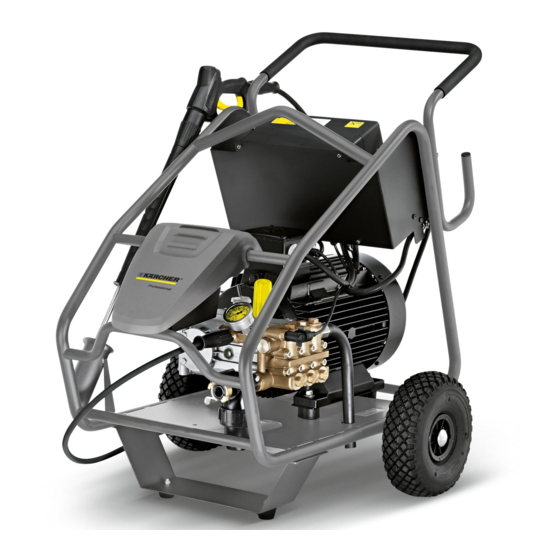
HD 9/50-4 Cage
Service manual
Kärcher HD 9/50-4 Cage Service Manual
Hide thumbs
Also See for HD 9/50-4 Cage
:
Manual
(340 pages)
1
Table Of Contents
2
3
4
5
6
7
8
9
10
11
12
13
14
15
16
17
18
19
20
21
22
23
24
25
26
27
28
29
30
31
32
33
34
35
36
37
page
of
37
Go
/
37
Contents
Table of Contents
Troubleshooting
Bookmarks
Table of Contents
Table of Contents
1 Preface
2 Safety Instructions
Hazard Levels
3 Technical Features
Drive
HD 9/50-4 Cage, HD 13/35-4 Cage
HD 9/50 PE Cage, HD 13/35 PE Cage
Pump
Control
Accessories
4 Setup and Function
Total View HD 13/35-4 Cage, HD 9/50-4 Cage
Switch Box HD 13/35-4 Cage, HD 9/50-4 Cage
Indicator Lamp
Electric Motor HD 13/15-4, HD
Total View HD 13/15 PE, HD 9/50 PE
Petrol Engine HD 13/15 PE, HD 9/50 PE
Battery
Motor
Motor Electrics
Air Filter
Motor with Removed Air Filter Box
Speed Control
Intermediate Gear
Water Connection with Water Fine Filter
Pump
Pump Diagram
Crank Drive Disassembled
Cylinder Head, High Pressure Valves and Water Inlet
Cylinder Head, Overflow Valve
Safety Valve, Dry Run Protection Switch
Cylinder Head, Piston Seals
Overflow Valve
Overflow Valve, Explosion Drawing
Overflow Valve, Cross Section Drawing
Seal High Pressure Pump
Replace the Pressure and Suction Valves
Replace the Suction Valves
Replace Pressure Valves
Cylinder Head, Uninstall
Replace the Oil Rings
Replace the Piston
Pump Maintenance
Replace the Overflow Valve
5 Basic Settings and Service Procedures
Setting the Maximum Working Pressure
Setting the Minimum Working Pressure
Adjusting the Full Load Speed (PE Model Only)
6 Troubleshooting
7 Technical Specifications
Special Tools
Tightening Torques
8 Circuit Diagram
Advertisement
Quick Links
1
Hd 9/50-4 Cage, Hd 13/35-4 Cage
2
Total View Hd 13/35-4 Cage, Hd 9/50-4 Cage
3
Pump Diagram
4
Circuit Diagram
Download this manual
See also:
Manual
HD 9/50-4 Cage
HD 13/35-4 Cage
HD 9/50 PE Cage
HD 13/35 PE Cage
Service Manual
1
English 5.906-441.0 Rev. 01 (06/10)
Table of
Contents
Previous
Page
Next
Page
1
2
3
4
5
Advertisement
Table of Contents
Need help?
Do you have a question about the HD 9/50-4 Cage and is the answer not in the manual?
Ask a question
Questions and answers
Related Manuals for Kärcher HD 9/50-4 Cage
Pressure Washer Kärcher HD 13/35-4 Cage Manual
(340 pages)
Pressure Washer Kärcher HD 6/11-4 M Plus Manual
(360 pages)
Pressure Washer Kärcher HD 6/11-4 M Plus Operating Instructions Manual
Karcher pressure washers operating instructions (372 pages)
Pressure Washer Kärcher HD 6/11-4 M Plus Original Instructions Manual
(372 pages)
Pressure Washer Kärcher HD 6/13 ST Manual
(212 pages)
Pressure Washer Kärcher HD 13/35 Ge Manual
(346 pages)
Pressure Washer Kärcher HD 7/11-4 Cage User Manual
(196 pages)
Pressure Washer Kärcher HD 6/15-4 Operating Instructions Manual
(156 pages)
Pressure Washer Kärcher HD 6/15-4 Manual
(146 pages)
Pressure Washer Kärcher HD 6/16-4 M / MX Service Manual
(32 pages)
Pressure Washer Kärcher HD 9/20-4 M / MX Service Manual
(32 pages)
Pressure Washer Kärcher HD 901 B Manual
(248 pages)
Pressure Washer Kärcher HD 901 B Manual
(20 pages)
Pressure Washer Kärcher HD 7/16-4 ST Instructions Manual
(172 pages)
Pressure Washer Kärcher HD 7/16-4 ST-H User Manual
(172 pages)
Pressure Washer Kärcher HD 994 Instruction Manual
Karcher pressure washer instruction manual (16 pages)
This manual is also suitable for:
Hd 13/35 pe cage
Hd 13/35-4 cage
Hd 9/50 pe cage
Table of Contents
Print
Rename the bookmark
Delete bookmark?
Delete from my manuals?
Login
Sign In
OR
Sign in with Facebook
Sign in with Google
Upload manual
Upload from disk
Upload from URL


Need help?
Do you have a question about the HD 9/50-4 Cage and is the answer not in the manual?
Questions and answers