Table of Contents
Advertisement
Quick Links
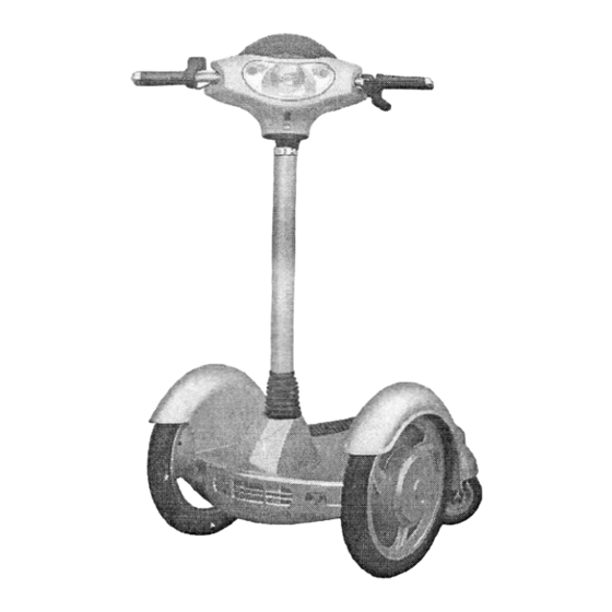
X-TREME 4 WHEEL
ELECTRIC PERSONAL TRANSPORTER
Model XT300
Due to continuing improvements, actual product may differ slightly from the product described herein.
Visit our Web site at:
http://www.x-tremescooters.com/
TO PREVENT SERIOUS INJURY, READ
AND UNDERSTAND ALL WARNINGS
AND INSTRUCTIONS BEFORE USE.
Page 1
Advertisement
Table of Contents

Subscribe to Our Youtube Channel
Related Manuals for X-TREME XT300


Summary of Contents for X-TREME XT300
- Page 1 X-TREME 4 WHEEL ELECTRIC PERSONAL TRANSPORTER Model XT300 Due to continuing improvements, actual product may differ slightly from the product described herein. Visit our Web site at: http://www.x-tremescooters.com/ TO PREVENT SERIOUS INJURY, READ AND UNDERSTAND ALL WARNINGS AND INSTRUCTIONS BEFORE USE.
-
Page 2: Product Specifications
PRODUCT SPECIFICATIONS Item Description Electrical Requirements Input power: AC90V-260V Charge Time: 4-8 Hours Output power: 36VDC Battery Type:36VDC, 12AH, Lead Acid (Rechargeable)(Qly.3) Motor Type:250 watt (Qty . 2) Fuse Type: F30A110V-Batteries F2A250V-Instrument panel and controls Bulb Type: Turn Signals = YH/3W40V / Headlight=40Volt, 10 Watt Power Cord Type: 18AWG×2C Power Cord Plug Type:3-Prong power cable Maximum Weight Capacity... -
Page 3: General Safety Rules
GENERAL SAFETY RULES WARNING! READ AND UNDERSTAND ALL INSTRUCTIONS Failure to follow all instructions listed below may result in Electric shock, fire, and/or serious injury. SAVE THESE INSTRUCTIONS 1. This product is intended for adult use only. Do not allow children to ride on or play with the XT-300. - Page 4 14. Do not overreach. Keep proper footing and balance at all times. Proper footing and balance enables better control in unexpected situations. 15. Do not use the XT-300 if the ignition Key does not turn it on or off. Any vehicle that cannot be controlled with the ignition Switch is dangerous and must be replaced.
- Page 5 Battery. 26. Do not attempt to charge a leaking Battery. 27. Use only accessories that are recommended by X-Treme Scooters for your XT-300. Accessories that may be suitable for one scooter may become hazardous when used on another.
- Page 6 ASSEMBLY AND OPERATING INSTRUCTIONS CAUTION! Always make sure the ignition switch is in its “OFF” position and the ignition Key is removed prior to setting up the XT-300, adding any accessories, or making adjustments to the unit. 2. The Scooter comes fully assembled, but will require some setup as follows: The Steering Bar Assembly must be positioned in place, the Wheels must be inflated and the Batteries must be charged.
- Page 7 Inflate The Wheels: Make sure to inflate the front and back Wheels to 36 PSI. Do not exceed 36 PSI. Use compressed air only. Product Features: Page 7...
- Page 8 To Charge The Batteries: 1. Before riding the Scooter for the first time you must charge the Batteries. Thereafter, if performance diminishes and/or the Voltage Gauge drops below 30V,you must recharge the Batteries. 2. Make sure the lgnition is in the “OFF” position. (See Figure B.) 3.
- Page 9 6. When the LED Light on the Gauge Panel turns to green, unplug the 3-Prong Power Cord Plug from its electrical outlet. Then, unscrew the ring of the Scooter’s Power Inlet Socket and disconnect the Charging Plug from the Socket. (See Figure C.) Pre-operating Safety Checks: 1.
-
Page 10: Inspection, Maintenance, And Cleaning
9. When finished riding the Scooter, gradually apply the Brakes until you come to a complete stop. Then, turn the lgnition Key to its “OFF” position. (See Figure B.) 10. Make sure to remove the lgnition Key. Then, store the Scooter in a clean, dry location out of reach of children. -
Page 11: Please Read The Following Carefully
PLEASE READ THE FOLLOWING CAREFULLY THE MANUFACTURER AND/OR DISTRIBUTOR HAS PROVIDED THE PARTS LIST AND ASSEMBLY DIAGRAM IN THIS MANUAL AS A REFERENCE TOOL ONLY. NEITHER THE MANUFACTURER OR DISTRIBUTOR MAKES ANY REPRESENTATION OF WARRANTY OF ANY KIND TO THE BUYER THAT HE OR SHE IS QUALIFIED TO REPLACE ANY PARTS OF THE PRODUCT. - Page 12 PARTS LIST & ASSEMBLY DIAGRAM - SCOOTER NOTE: Some parts are listed and shown for illustration purposes only, and are not available individually as replacement parts. Part Description Q’ty Part Description Q’ty Spring Washer Pulley Block Inner Steering Arm Hex Nut Cam Flange Hex Nut Seal...
- Page 13 PARTS LIST & ASSEMBLY DIAGRAM A – REAR WHEEL BRACKET PART A Rear Wheel Bracket Part Description Qty. Ball Bearing Retaining Ring Retaining Ring Retaining Ring Flat Washer Cam Bracket Transverse Coupling Bar Cam Flange Frame Ball Bearing Hex Screw Hex Key Screw NOTE: Some parts are listed and shown for illustration purposes only,...
- Page 14 PARTS LIST & ASSEMBLY DIAGRAM B – WHEEL ASSEMBLY Part Description Q’ty Ball Bearing Brake Rotor Inner Hub Outer Hub Hex Locking Screw Cap Screw Cross Countersunk Screw Cap Screw Bushing Flat Hook Washer Wheel NOTE: Some parts are listed and shown for illustration purposes only, and are not available individually as replacement parts.
- Page 15 PARTS LIST & ASSEMBLY DIAGRAM C – STEERING BAR ASSY. Part Description Q’ty Column Seal Dust Cover Handlebar Front Panel Cover Rear Panel Cover Grip Brake Handle Quick Release Lever Assembly Page 15...
- Page 16 ENJOY YOUR RIDING! For General Information or Parts Visit www.x-tremescooters.com For Technical Support or Assistance Visit www.x-tremescooters.com/support/ Page 16...
Need help?
Do you have a question about the XT300 and is the answer not in the manual?
Questions and answers