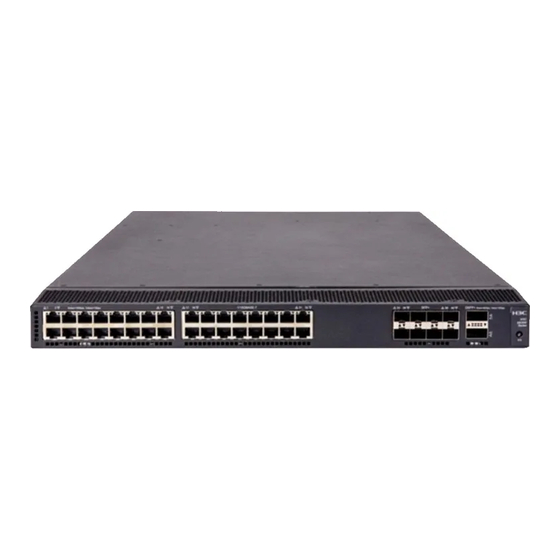
H3C S6300 Installation Manual
Hide thumbs
Also See for S6300:
- Configuration manual (55 pages) ,
- Troubleshooting manual (32 pages) ,
- Evb configuration manual (25 pages)

Related Manuals for H3C S6300


Summary of Contents for H3C S6300
-
Page 1: Installation Guide
H3C S6300 Switch Series Installation Guide Hangzhou H3C Technologies Co., Ltd. http://www.h3c.com Document version:6W101-20160714... - Page 2 , H3CS, H3CIE, H3CNE, Aolynk, Care, , IRF, NetPilot, Netflow, SecEngine, SecPath, SecCenter, SecBlade, Comware, ITCMM and HUASAN are trademarks of Hangzhou H3C Technologies Co., Ltd. All other trademarks that may be mentioned in this manual are the property of their respective owners Notice The information in this document is subject to change without notice.
- Page 3 Preface H3C S6300 Switch Series Installation Guide describes the procedures for installing, accessing, and troubleshooting the H3C S6300 Switch Series. This preface includes the following topics about the documentation: • Audience • Conventions • About the H3C S6300 documentation set •...
- Page 4 GUI conventions Convention Description Window names, button names, field names, and menu items are in Boldface. For Boldface example, the New User window appears; click OK. Multi-level menus are separated by angle brackets. For example, File > Create > > Folder.
- Page 5 Description Represents a security card, such as a firewall, load balancing, NetStream, SSL VPN, IPS, or ACG card. About the H3C S6300 documentation set The H3C S6300 documentation set includes the following categories of documents: Category Documents Purposes Product description and Marketing brochures Describe product specifications and benefits.
-
Page 6: Obtaining Documentation
Obtaining documentation Access the most up-to-date H3C product documentation on the World Wide Web at http://www.h3c.com. Click the following links to obtain different categories of product documentation: [Technical Support & Documents >Technical Documents]—Provides hardware installation, software upgrading, and software feature configuration and maintenance documentation. -
Page 7: Table Of Contents
Contents Preparing for installation ················································································· 1 Safety recommendations ··································································································································· 1 Examining the installation site ···························································································································· 1 Temperature/humidity ································································································································ 1 Cleanliness ················································································································································· 2 EMI ····························································································································································· 2 Laser safety ················································································································································ 3 Installation tools ················································································································································· 3 ... - Page 8 Appendix A Chassis views and technical specifications ······························· 34 Chassis views ·················································································································································· 34 S6300-42QF ············································································································································· 34 S6300-42QT ············································································································································· 35 S6300-48S ··············································································································································· 36 S6300-52QF ············································································································································· 37 Technical specifications ··································································································································· 38 Appendix B FRUs and compatibility matrixes ··············································· 40 ...
-
Page 9: Preparing For Installation
Preparing for installation Safety recommendations To avoid any equipment damage or bodily injury, read the following safety recommendations before installation. Note that the recommendations do not cover every possible hazardous condition. • Before cleaning the switch, unplug all power cords from the switch. Do not clean the switch with wet cloth or liquid. -
Page 10: Cleanliness
For the temperature and humidity requirements of different switch models, see "Technical specifications." Cleanliness Dust buildup on the chassis might result in electrostatic adsorption, which causes poor contact of metal components and contact points, especially when indoor relative humidity is low. In the worst case, electrostatic adsorption can cause communication failure. -
Page 11: Laser Safety
Laser safety WARNING! Do not stare into any fiber port when the switch has power. The laser light emitted from the optical fiber might hurt your eyes. The switch is a Class 1 laser device. Installation tools The installation tools are not provided with the switch. Prepare them yourself. •... -
Page 12: Installing The Switch
Installing the switch in a 19-inch rack Installation prerequisites To close the rack door easily, make sure the rack depth for the S6300-42QT switch is a minimum of 1000 mm (39.37 in). The distance from the front to the rear posts of the rack must meet the requirements described Table You must use both the mounting bracket and the rack mounting rail kit to rack-mount the switch. -
Page 13: Mounting Brackets And Rack Mounting Rail Kit
Switch model Installation method distance distance Using mounting brackets and short • 401 mm (15.79 in) 654 mm (25.75 in) S6300-42QF slide rails (supplied with the switch) • S6300-48S Using mounting brackets and long • S6300-52QF 621 mm (24.45 in) 874 mm (34.41 in) -
Page 14: Attaching The Mounting Brackets, Chassis Rails, And Grounding Cable To The Chassis
Use the primary grounding point whenever possible. If the primary grounding point fails or is not suitable for the installation site, use one of the auxiliary grounding points. Figure 5 Mounting and grounding positions of the S6300-42QT (1) Auxiliary grounding point 2... - Page 15 Attaching the mounting brackets and chassis rails to the chassis Align the mounting brackets with the screw holes in the rear mounting position (see Figure 7) or front mounting position (see Figure Use M4 screws (supplied with the switch) to attach the mounting brackets to the chassis. Align the chassis rails with the rail mounting holes in the chassis: If the mounting brackets are in the rear mounting position, align the chassis rails with the screw holes at the front of the side panels (see...
-
Page 16: Attaching The Slide Rails To The Rack
Figure 8 Attaching the front mounting brackets/chassis rails to the chassis NOTE: H3C recommends that you use the primary grounding point or auxiliary grounding point 1 because the grounding cable and grounding screw that come with the switch are suitable only for these two grounding points. -
Page 17: Mounting The Switch In The Rack
Align the screw holes in one slide rail with the cage nuts in the rack post on one side, and use screws (user supplied) to attach the slide rail to the rack, as shown in Figure Repeat the preceding step to attach the other slide rail to the rack post on the other side. Keep the two slide rails at the same height so the slide rails can attach into the chassis rails. - Page 18 Figure 10 Mounting the switch in the rack (1) Figure 11 Mounting the switch in the rack (2)
-
Page 19: Grounding The Switch
Grounding the switch WARNING! Correctly connecting the switch grounding cable is crucial to lightning protection and EMI protection. The power input end of the switch has a noise filter, whose central ground is directly connected to the chassis to form the chassis ground (commonly known as PGND). You must securely connect this chassis ground to the earth so the faradism and leakage electricity can be safely released to the earth to minimize EMI susceptibility of the switch. -
Page 20: Grounding The Switch By Using The Ac Power Cord
(3) Grounding post (4) Grounding strip NOTE: • H3C recommends that you use the primary grounding point or auxiliary grounding point 1, because the grounding cable and grounding screw provided with the switch are applicable only to these two grounding points. -
Page 21: Installing/Removing A Fan Tray
Figure 13 Grounding through the PE wire of the AC power cord (1) Three-wire AC power cable (2) Chassis rear panel NOTE: To guarantee the grounding effect, use the grounding cable provided with the switch to connect to the grounding strip in the equipment room as long as possible. Installing/removing a fan tray CAUTION: To ensure good ventilation for the switch:... -
Page 22: Removing A Fan Tray
14). If the captive screw cannot be tightly fastened, verify the installation of the fan tray. Figure 14 Installing an LSWM1FANSC/LSWM1FANSCB/LSWM1HFANSC/LSWM1HFANSCB fan tray (on the S6300-52QF) Removing a fan tray WARNING! • Take out the fan tray after the fans completely stop rotating. -
Page 23: Installing A Power Module
Figure 15 Installation procedure Figure 16 Removal procedure Installing a power module CAUTION: • Follow the forward inertia of the power module when inserting it into the chassis, and make sure the power module has firm contact with the connectors on the backplane. •... -
Page 24: Removing A Power Module
Figure 18 Installing a power filler module Removing a power module CAUTION: If the switch has two power modules, removing one power module does not affect the operation of the switch. If the switch has only one power module, removing the power module powers off the switch. -
Page 25: Connecting The Power Cord
Figure 19 Removing the DC power cord (1) Press the tabs on the power cord connector (2) Pull the power cord connector out with your thumb and forefinger Figure 20 Removing the power module (1) Pivot the latch to the right with your thumb (2) Pull the power module out Connecting the power cord Connecting the AC power module... -
Page 26: Connecting The Dc Power Module
Use a cable tie to secure the power cord to the handle of the power module, as shown in Figure Connect the other end of the power cord to an AC power outlet. Figure 21 Connecting the LSVM1AC300 or LSVM1AC650 power module on the S6300-52QF switch (1) Cable tie... - Page 27 • The correct power source is used. • The power cords are correctly connected. • All the interface cables are cabled indoors. If any cable is routed outdoors, verify that the socket strip with lightning protection and lightning arresters for network ports have been correctly connected.
-
Page 28: Accessing The Switch For The First Time
Accessing the switch for the first time Setting up the configuration environment The first time you access the switch you must use a console cable to connect a console terminal, for example, a PC, to the console port on the switch. Figure 23 Connecting the console port to a terminal Connecting the console cable Console cable... -
Page 29: Setting Terminal Parameters
NOTE: • Identify the mark on the console port and make sure you are connecting to the correct port. • The serial ports on PCs do not support hot swapping. If the switch has been powered on, connect the console cable to the PC before connecting to the switch, and when you disconnect the cable, first disconnect from the switch. - Page 30 Figure 26 Setting the serial port used by the HyperTerminal connection Set Bits per second to 9600, Data bits to 8, Parity to None, Stop bits to 1, and Flow control to None, and click OK. Figure 27 Setting the serial port parameters Select File >...
- Page 31 Figure 28 HyperTerminal window On the Settings tab, set the emulation to VT100 and click OK. Figure 29 Setting terminal emulation in Switch Properties dialog box...
-
Page 32: Powering On The Switch
After the startup completes, you can access the CLI to configure the switch. For more information about the configuration commands and CLI, see H3C S6300 Switch Series Configuration Guides and H3C S6300 Switch Series Command References. -
Page 33: Setting Up An Irf Fabric
Setting up an IRF fabric You can use H3C IRF technology to connect and virtualize S6300 switches into a large virtual switch called an "IRF fabric" for flattened network topology, and high availability, scalability, and manageability. IRF fabric setup flowchart... -
Page 34: Planning Irf Fabric Setup
Distribute the IRF member switches in different racks to implement the top-of-rack (ToR) access solution for a data center. As your business grows, you can plug H3C S6300 switches into the IRF fabric to increase the switching capacity without any topology change or replacement. -
Page 35: Identifying Physical Irf Ports On The Member Switches
You can bind several ports of the same type to an IRF port for increased bandwidth and availability. Figure 31 Figure 32 show the topologies of an IRF fabric made up of three S6300 switches. The IRF port connections in the two figures are for illustration only, and more connection methods are available. -
Page 36: Planning The Cabling Scheme
All ports on the front panel of the S6300 switch can be used for IRF connections. Follow these guidelines when you identify 1/10-GE Ethernet ports and SFP+ ports to be used for IRF connections: • On an S6300-42QF, S6300-52QF, or S6300-48S switch, the SFP+ ports are grouped by port number in ascending order, starting from one. - Page 37 Figure 33 Connecting the switches in one rack Figure 34 IRF fabric topology Connecting the IRF member switches in a ToR solution You can install IRF member switches in different racks side by side to deploy a top of rack (ToR) solution.
-
Page 38: Configuring Basic Irf Settings
• To bind the ports on an interface card to an IRF port, you must install the interface card first. For how to install an interface card, see H3C S6300 Switch Series Interface Cards User Guide. • Execute the display irf configuration command to verify the basic IRF settings. - Page 39 To avoid IP address collision and network problems, configure at least one multi-active detection (MAD) mechanism to detect the presence of multiple identical IRF fabrics and handle collisions. For more information about MAD detection, see H3C S6300 Switch Series IRF Configuration Guide.
-
Page 40: Maintenance And Troubleshooting
You can use the LEDs on the power module to identify a power module failure. For more information about the LEDs on a power module, see H3C LSVM1AC300 & LSVM1DC300 Power Modules User Manual and H3C LSVM1AC650 & LSVM1DC650 Power Modules User Manual. -
Page 41: Garbled Terminal Display
Garbled terminal display If terminal display is garbled, verify that the following settings are configured for the terminal, for example, HyperTerminal: • Baud rate—9,600 • Data bits—8 • Parity—none • Stop bits—1 • Flow control—none • Emulation—VT100... -
Page 42: Appendix A Chassis Views And Technical Specifications
"Installing/removing a power module." The S6300-42QF switch also comes with the fan tray slots empty. You must install two fan trays of the same model for the switch. In Figure 37, two LSWM1FANSC fan trays are installed. For more information about installing and removing a fan tray, see "Installing/removing a fan... -
Page 43: S6300-42Qt
"Installing/removing a power module." The S6300-42QT switch also comes with the fan tray slots empty. You must install two fan trays of the same model for the switch. In Figure 40, two LSWM1HFANSC fan trays are installed. For more information about installing and removing a fan tray, see "Installing/removing a fan... -
Page 44: S6300-48S
"Installing/removing a power module." The S6300-48S switch also comes with the fan tray slots empty. You must install two fan trays of the same model for the switch. In Figure 43, two LSWM1FANSC fan trays are installed. For more information about installing and removing a fan tray, see "Installing/removing a fan... -
Page 45: S6300-52Qf
"Installing/removing a power module." The S6300-52QF switch also comes with the fan tray slots empty. You must install two fan trays of the same model for the switch. In Figure 46, two LSWM1FANSC fan trays are installed. For more information about installing and removing a fan tray, see "Installing/removing a fan... -
Page 46: Technical Specifications
Figure 47 Left side panel (1) Primary grounding point (2) Auxiliary grounding point 1 Technical specifications Item S6300-42QF S6300-42QT S6300-48S S6300-52QF 43.6 × 440 × 460 43.6 × 440 × 660 mm 43.6 × 440 × 460 43.6 × 440 × 460 Dimensions (H ×... - Page 47 Item S6300-42QF S6300-42QT S6300-48S S6300-52QF • • • • Single AC Single AC Single AC input: Single AC input: 153 W input: 343 W 160 W input: 191 W • • • • Dual AC Dual AC Dual AC inputs:...
-
Page 48: Appendix B Frus And Compatibility Matrixes
Appendix B FRUs and compatibility matrixes This appendix describes the field replaceable units (FRUs) available for the S6300 switches and their compatibility. All the FRUs in this appendix are hot swappable. Power modules Power Specifications Switch model Remarks module •... -
Page 49: Fan Trays
Fan trays Item Specifications LSWM1FANSC (for the S6300-42QF/S6300-48S/S6300-52QF switch) Fans Two 40 × 40 × 28 mm (1.57 × 1.57 × 1.1 in) fans Fan speed 18500 R.P.M Max airflow 45 CFM Back to front (Fans blow air from the power module side to the network Airflow direction port side.) - Page 50 Item Specifications Documentation reference H3C LSWM1HFANSC & LSWM1HFANSCB Installation Manual CAUTION: The switch comes with the fan tray slots empty. You must install two fan trays for the switch for adequate heat dissipation, and their models must be the same. You must not power on the switch...
-
Page 51: Appendix C Ports And Leds
NOTE: USB devices from different vendors vary in compatibility and driver. H3C does not guarantee correct operation of USB devices from other vendors on the switch. If a USB device does not operate... -
Page 52: Sfp+ Port
SFP+ port The switch provides SFP+ ports. You can plug the SFP transceiver modules in Table 7, the SFP+ transceiver modules in Table 8, and the SFP+ cables in Table 9 into the SFP+ ports as needed. You can use the SFP+ ports as IRF physical ports to connect the switches in an IRF deployment. Table 7 1000 Mbps SFP transceiver modules available for the SFP+ ports Multimode fiber Central... -
Page 53: Qsfp+ Port
For the SFP transceiver module specifications, see H3C Low End Series Ethernet Switches Pluggable Modules Manual. The SFP+ cables available for the H3C S6300 switches are 10 Gbps SFP+ Cu cables, as shown Figure Figure 48 SFP+ cable... - Page 54 NOTE: The QSFP-40G-SR4-MM850 transceiver module and QSFP-40G-CSR4-MM850 transceiver module can be used to connect one 40G QSFP+ port to four 10G SFP+ ports. The QSFP+ transceiver modules and SFP+ transceiver modules to be connected must be the same in specifications, including central wavelength and fiber diameter. Table 10 QSFP+ transceiver modules available for the switch Multimode fiber Central...
-
Page 55: 1/10Gbase-T Autosensing Ethernet Port
(4) SFP+ module NOTE: • To guarantee the functionality of the QSFP+ ports, use only H3C QSFP+ transceiver modules and cables on the S6300-42QF, S6300-42QT, and S6300-52QF switches. • The QSFP+ transceiver modules and cables available for this switch series are subject to change over time. -
Page 56: Leds
If the device connects to two distribution frames, connect port 1 on the device to port 1 on distribution frame 1, port 2 on the device to port 1 on distribution frame 2, and port 3 on the device to port 2 on distribution frame 1. LEDs System status LED The system status LED shows the operating status of the switch. -
Page 57: 1/10Gbase-T Autosensing Ethernet Port Leds
LED status Description Flashing yellow The port is sending or receiving data at 10 Gbps. No transceiver module or cable has been installed or no link is present on the port. 1/10GBase-T autosensing Ethernet port LEDs Table 16 1/10GBase-T autosensing Ethernet port LED description Status Description Steady green... -
Page 58: Appendix D Cooling System
NOTE: To ensure correct ventilation, fan trays on the switch must have the same air flow direction. Figure 51 Power module side to network port side air flow direction (S6300-42QT chassis with LSWM1HFANSC fan trays) Figure 52 Network port side to power module side air flow direction (S6300-42QT chassis... -
Page 59: Index
Index A C E F G I L P S T V Installing/removing a fan tray,13 Installing/removing a power module,14 Accessing the IRF fabric to verify the IRF fabric setup flowchart,25 configuration,30 LEDs,48 Chassis views,34 Configuration terminal problems,32 Configuring basic IRF settings,30 Planning IRF fabric setup,26...
Need help?
Do you have a question about the S6300 and is the answer not in the manual?
Questions and answers