Advertisement
Quick Links
I NS T R U C T I ON S
Type OJ Microline OTN
57943 -10/06 (BJ)
English
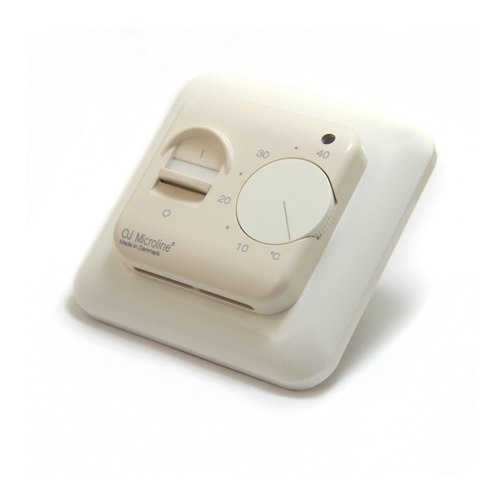
OJ Microline, electronic thermostat for
mounting in standard wall box. The thermostat
is adjustable to required temperature from
+5/+40˚C. The LED shows that the heat is ON.
OJ MICROLINE PRODUKTPROGRAM
OTN-1991H11
with floor sensor
OTN-1999H
with built-in sensor
CE MARKING
OJ declare under their own responsibility that
this product meets the requirements of the
European Council's directive 89/336 and
successive modifications as to electro-magnetic
compatibility and the Council directive 73/23 as
to electrical equipment to be applied within
certain voltage ranges.
Standards applied
EN 61000-6-3, EN 61000-6-2, EN 60 730-1 and
EN 60730-2-9.
The product may only be energised when the
entire installation meets the current directive
requirements.
When the product is installed according to this
instructions guide and the current installation
guidelines, it is covered by factory guarantee.
If the product has been exposed to damage e.g.
in transport, it must be checked and overhauled
by qualified staff before the product is
connected to the power.
TECHNICAL DATA
Voltage
. . . . . . .230V AC +10/-15%, 50/60 Hz
Current consumption . . . . . . . . . . . . . . . . . .6 VA
Max. fuse . . . . . . . . . . . . . . . . . . . . . . . . . . .16A
Built-in switch . . . . . . . . . . . . . . . . . .1-pole, 16A
Output relay - make contact . . . . . . . .SPST-NO
Load:
OTN-1991H11
. . . . . . . . .14A, 3200W
OTN-1999H . . . . . . . . . . . .16A, 3600W
Regulation principle . . . . . . . . . . . . . . . .ON/OFF
Temperature scale . . . . . . . . . . . . . . . .+5/+40°C
Difference/hysteresis . . . . . . . . . . . . . . . . .0.4°C
Setback temperature . . . . . . . . . . . . . .fixed 5˚C
- control voltage signal . . . . . . . . . . . . .230V AC
Scale limitation . . . . . . . . . . . . . . . . . .min./max.
Error circuit fuse at . . . . . . . . . . . . . . . . . .-20°C
Ambient temperature . . . . . . . . . . . . . . .0/+25°C
Dimensions . . . . . . . . . . .H/80, W/80, D/50 mm
Protection:
OTN-1991H11 . . . . . . . . . . . . . . . .IP21
OTN-1999H . . . . . . . . . . . . . . . . . .IP20
Because of tolerances the temperature range
may vary from +5/+45°C.
The thermostat is free of maintenance.
CLASSIFICATION
The product is a class II device (reinforced
insulation) and the product must be connected
to the following conductors:
1)
Phase
(L)
2)
Neutral
(N)
WARNING – Important Safety Instructions
Isolate supply before carrying out any
installation or maintenance work on this control
unit and associated components. This control
Type: OJ Microline OTN
unit and associated components should only be
installed by a competent person (i, e qualified
electrician). Electrical installation to be in
accordance with latest IEE Wiring Regulations
and appropriate Statutory Regulations.
Mounting of sensor
Floor sensor: Placed in an approved non
conductive installation pipe in accordance with
EN 61386-1, which is embedded in the floor.
(fig. 4) The pipe is closed in the end and placed
as high as possible in the concrete layer. The
installation pipe must be centered in between
the heating cable.
Sensor cable can be extended up to 100 m. by
means of a separate cable. If the extension
cable is lighter than H05VV-F, it shall equally be
installed in an unbroken installation pipe
between the sensor cable and the extension
cable. Two remaining cores of a multi-core
cable which, for example, supplies current to
the floor heating wires, must not be used. The
switching peaks of such current supply lines
may create interfering signals that prevent
optimum controller function. If a shielded cable
is used, the shield must not be earthed but
must be connected to terminal 7. The two-core
cable must be placed in a separate pipe.
PLACEMENT OF THERMOSTAT WITH BUILT-
IN SENSOR
Thermostat is to be mounted on the wall with
free air circulation around it (fig. 5). Furthermore
it has to be placed where it is not influenced by
any other heating sources (e.g. the sun), draft
from doors or windows, or by the temperature
of an exterior wall.
OJ Microline units contain a fault interrupter
circuit which interrupts the heating in case of
disconnected or short-circuited sensors.
MOUNTING OF THERMOSTAT (fig. 1-3)
1. Remove the control knob (A).
2. Screw (B) should be unscrewed and the
cover lifted off.
3. Electrical connections can be made as
shown in the wiring diagram.
4. Mount the backing plate. Use only the round
holes.
5. The thermostat can now be filled into the
wall box.
- frame and cover is mounted
- thermostat knob is replaced
SETBACK TEMPERATURE
Setback of temperature setting is activated by a
230 V (L) signal from an external time switch to
terminal 5. Setback temperature is fixed 5˚C.
TEMPERATURE SETTING
OJ Microline has a scale range of +5/+40˚C. To
assist the adjustment, the thermostat has a LED
(D) which will glow RED when the heating is ON.
The thermostat should be set to maximum
temperature setting until the desired
temperature of the room or floor is achieved.
The control knob should then be turned back
until the LED goes out. Fine adjustments can be
made over the next 1/2 days to suit individual
requirements.
THERMOSTAT ADJUSTMENT
When the room temperature has been
stabilized, the thermostat set position may be
adjusted to match actual room temperature.
Measure the temperature of the room with an
accurate thermometer. Remove control knob
and reposition it so that the indicated
temperature line shows the same as the
measured temperature. This adjustment can be
done in steps of 3°C.
MAX./MIN. TEMPERATURE
A locking mechanism is positioned behind the
control knob to limit the amount of adjustment
possible. By loosening the little screw (C), the
scale range can be locked, e.g. between 20˚C
and 25˚C. The red ring indicates the maximum
temperature and the blue ring indicates the
minimum temperature.
FIGURS
Fig. 1
OJ Microline cover with knob.
Fig. 2
Connection of OTN-1991H11 .
Fig. 3
Connection of OTN-1999H.
Fig. 4
Mounting of floor sensor.
Fig. 5
Mounting of thermostat.
Fig. 6
Scheme with sensor values.
Dansk
OJ Microline, elektronisk termostat for
montering i standard vægdåse. Termostaten
kan indstilles på ønsket temperatur fra
+5/+40˚C. Lysdiode viser at varme er indkoblet.
OJ MICROLINE PRODUKTPROGRAM
OTN-1991H11
OTN-1999H
med indbygget føler
CE MÆRKNING
OJ Electronics A/S erklærer under ansvar, at
dette produkt opfylder Rådets Direktiv 89/336
og efterfølgende ændringer om
elektromagnetisk kompatibilitet samt Rådets
Direktiv 73/23 og efterfølgende ændringer om
elektrisk materiel bestemt til anvendelse inden
for visse spændingsgrænser.
Anvendte standarder
EN 61000-6-3, EN 61000-6-2, EN 60 730-1 og
EN 60730-2-9.
Produktet må kun tages i brug, når hele
installationen opfylder gældende direktivkrav.
Når produktet er installeret i henhold til denne
vejledning og gældende installationsforskrifter,
er den omfattet af fabriksgaranti.
Hvis produktet har været udsat for fysisk
overlast eller beskadigelse, f.eks. under
transport, skal produktet efterses og kontrolleres
af kvalificeret personale før produktet tilsluttes
forsyningsnettet.
TEKNISKE DATA
Spænding . . . . . .230V AC +10/-15%, 50-60 Hz
Eget forbrug max. . . . . . . . . . . . . . . . . . . . .6 VA
Max. forsikring . . . . . . . . . . . . . . . . . . . . . . .16A
Indbygget afbryder . . . . . . . . . . . . .1-polet, 16A
Udgangsrelæ . . . . . .Sluttekontakt - SPST - NO
Udgangsstrøm:
OTN-1991H11
. . . . . . . . .14A, 3200W
OTN-1999H . . . . . . . . . . . .16A, 3600W
Reguleringsprincip . . . . . . . . . . . . . . . . .ON/OFF
Temperatur-område . . . . . . . . . . . . . . .+5/+40˚C
Difference/hysterese . . . . . . . . . . . . . . . . .0,4°C
med gulvføler
1
Advertisement

Related Manuals for OJ Electronics Microline OTN-1991H11


Summary of Contents for OJ Electronics Microline OTN-1991H11
- Page 1 ..230V AC +10/-15%, 50/60 Hz circuit which interrupts the heating in case of OJ Electronics A/S erklærer under ansvar, at Current consumption ....6 VA disconnected or short-circuited sensors.
- Page 2 H05W-F, skal det ligeledes CE MÄRKNING kabeln i ett separat rör. installeres i et ubrudt installationsrør mellem OJ Electronics A/S förklarar under ansvar att følerkabel og termostat. De to resterende ledere produkten uppfyller Rådets Direktiv 89/336 och PLACERING AV TERMOSTAT MED INBYGGD i et flerlederkabel, som f.eks.
- Page 3 Monijohdinkaapelissa, joka esimerkiksi pudotuksella tuo virran lattialämmityksen johtoihin, kahta CE PRÜFZEICHEN jäljellä olevaa johdinta ei tule käyttää. Tällaisten OJ Electronics A/S erklärt in eigener Verant - OTN-1999H sisään rakennetulla huoneanturilla virransyöttöjohtojen kytkentäpiikit voivat wortung, dass dieses Produkt der Direktive des lämpötilan pudotuksella...
- Page 4 100 m par un câble distinct. Si le câble de Den Montageort so auswählen, daß der Fühler OJ Electronics A/S déclare que ce produit rallonge est plus léger que H05VV-F, il doit aussi nicht einer fremden Energiequelle, wie z.B. der répond aux critères stipulés par la directive...
- Page 5 CE MAKERING lichter is dan H05VV-F, moet hij ook in een OTN jest termostatem do montowania w OJ Electronics A/S verklaart, dat het produkt installatiebuis uit één stuk geplaatst worden standardowych puszkach ściennych. Termostat voldoet aan de eisen, zoals gesteld in de tussen de sensorkabel en de thermostaat.
- Page 6 Termostat należy umieścić w miejscu, gdzie jest OTN-1999H Ò ‚ÒÚÓÂÌÌ˚Ï Ò˜ÂÚ˜ËÍÓÏ instrukcją i obowiązującymi przepisami fabryka swobodna cyrkulacja powietrza woko ´ ł OJ Electronics A/S udziela gwarancji na ten termostatu (zobacz rys.5). Ponadto termostat M‡ÍËӂ͇ CE produkt. należy umieścić w miejscu, gdzie nie jest OJ Electronics A/S Ò...
- Page 7 Монтаж должен производиться с Á‡ÏÂÂÌ̇fl. TӘ̇fl ̇ÒÚÓÈ͇ ÔÓËÁ‚Ó‰ËÚÒfl T ermostat bakım istemez. соблюдением всех действующих правил и ‚ ÌÂÒÍÓθÍÓ ÔËÂÏÓ‚, Ò ¯‡„ÓÏ ÓÍ. 3°C. инструкций по установке MAKC./Màç. TEMèEêATìêA SINIFLANDIRMA электрооборудования. 3‡ „ÛÎËÓ‚Ó˜ÌÓÈ Û˜ÍÓÈ ÚÂÏÓÒÚ‡Ú‡ Ürün bir sınıf II cihazdır (geliştirilmiş izolasyon) ve ̇ıÓ‰ËÚÒfl...
- Page 8 MAKS./MIN. SICAKLIK Olası ayar miktarını sınırlamak üzere kumanda düğmesinin arkasında bir kilitleme mekanizması bulunur. Küçük vida (C) gevşetilerek, skala aralığı örn. 20°C ve 25°C arasında kilitlenebilir. Kırmızı halka, maksimum sıcaklığı ve mavi halka, minimum sıcaklığı gösterir. ŞEKİLLER Şek. 1 Düğmeli OJ Microline Şek.
- Page 9 Chinese...
- Page 11 Fig. 3 - OTN-1999H Fig. 5 Fig. 6 Type ETF-.99 Temp.(˚C) Value (ohm) OJ Electronics A/S 64000 Stenager 13B · DK-6400 Sønderborg 38000 TEL +45 73 12 13 14 · FAX +45 73 12 13 13 oj@oj.dk · www.oj.dk 23300...
- Page 12 5 7 9 4 3...
Need help?
Do you have a question about the Microline OTN-1991H11 and is the answer not in the manual?
Questions and answers