Thrane&Thrane Explorer 727 Installation Manual
Bgan terminal
Hide thumbs
Also See for Explorer 727:
- Installation manual (110 pages) ,
- Getting started (8 pages) ,
- User manual (148 pages)
Table of Contents
Advertisement
Quick Links
Advertisement
Table of Contents

Subscribe to Our Youtube Channel
Related Manuals for Thrane&Thrane Explorer 727


Summary of Contents for Thrane&Thrane Explorer 727
- Page 2 Thrane & Thrane A/S ® EXPLORER Installation manual Document number: TT98-126844-B Release date: March 27, 2008...
- Page 3 Information in this document is subject to change without notice and does not represent a commitment on the part of Thrane & Thrane A/S. We recommend downloading the latest version of the manual from the Thrane & Thrane A/S web site www.thrane.com. Copyright ©...
-
Page 4: Safety Summary
The minimum safety distance is 1 m to the side and above the antenna when the EXPLORER 727 is powered. The safety distance of 1 m does not apply directly below the antenna, as the radiation forms a hemisphere above the antenna. - Page 5 Power supply The voltage range is 10.5 - 32 V DC; 14 A - 5.5 A. Be aware of high start-up peak current: 20 A at 24 V, 5 ms. Do not operate in an explosive atmosphere Do not operate the equipment in the presence of flammable gases or fumes. Operation of any electrical equipment in such an environment constitutes a definite safety hazard.
- Page 6 About the manual Intended readers This is an installation manual for the EXPLORER 727 system. The readers of the manual include installers of the system and service personnel. Personnel installing or servicing the system must be properly trained and authorized by Thrane & Thrane. It is...
- Page 7 A short guide to the most important functions of the EXPLORER systems. EXPLORER 727 Getting Started TT98-126880 Explains how to start up your EXPLORER 727 system and make the first call or data session. Thrane & Thrane IP Handset, User Manual TT98-126059 Explains the features and functions of the Thrane &...
- Page 8 Typography In this manual, typography is used as indicated below: Bold is used for the following purposes: • To emphasize words. Example: “Do not touch the antenna”. • To indicate what the user should select in the user interface. Example: “Select Settings > LAN”. Italic is used to emphasize the paragraph title in cross- references.
- Page 9 viii...
-
Page 10: Table Of Contents
Table of contents Chapter 1 System units Introduction ............... 1 ® EXPLORER terminal ........... 1 EXPLORER ® 727 antenna ........2 IP handset and cradle ..........3 Chapter 2 Installing the system Unpacking ..............5 2.2 Placing the antenna ...........6 2.3 Installing the antenna ..........7 2.4 Placing the terminal ..........16 2.5 Installing the terminal ..........17 Chapter 3... - Page 11 Table of contents 4.7 Discrete I/O interface ..........38 Chapter 5 Starting up the system Using the SIM card ........... 41 5.2 Powering the system ..........43 5.3 Entering the SIM PIN for the terminal ......45 5.4 Operating the system ..........47 Chapter 6 Troubleshooting Reset button ............49 6.2 Status signaling ............52...
-
Page 12: Chapter 1 System Units
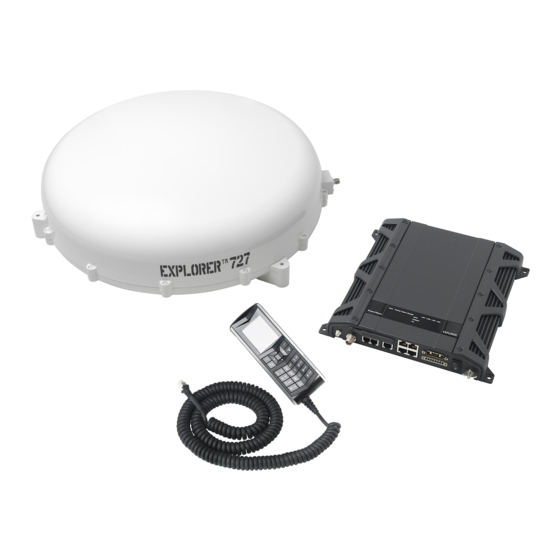
Chapter 1 System units 1.1 Introduction The basic system consists of three units: The terminal, the antenna and the IP handset with cradle. ® 1.2 EXPLORER terminal The terminal, which contains the primary electronic parts, is designed for wall or desktop installation. The terminal supplies 23.0 - 30.0 V DC to the antenna through a single coaxial cable. -
Page 13: Explorer ® 727 Antenna
® 1.3 EXPLORER 727 antenna The EXPLORER 727 antenna is a mechanical tracking antenna, consisting of a 2-axis stabilized antenna with RF-unit, antenna control unit and GPS antenna. The antenna is dedicated to the Inmarsat BGAN (Broadband Global Area Network) system and is designed for roof mounting on a vehicle. All communication between the antenna and terminal passes through a single coaxial cable. -
Page 14: Ip Handset And Cradle
Chapter 1: System units 1.4 IP handset and cradle 1.4.1 Thrane & Thrane IP handset Besides the normal functions of an IP handset, the Thrane & Thrane IP handset also provides a user interface for the EXPLORER system. The IP handset connects to the LAN interface of the terminal, and is power supplied with Power over Ethernet (PoE) through the LAN interface. - Page 15 Chapter 1: System units 1.4.2 Thrane & Thrane IP cradle The IP cradle serves as a holder for the IP handset. It is power supplied from the terminal using Power over Ethernet (PoE). The cradle connects to the handset with a coil cord and to the terminal with a standard LAN cable. IP handset and cradle...
-
Page 16: Chapter 2 Installing The System
Getting Started leaflet • Quick Guide • EXPLORER 727 CD including electronic versions of User manual, Installation manual, Quick Guide and Getting Started guide. Inspect all units and parts for possible transport damage. Note For information on how to install the IP handset and cradle, refer to... -
Page 17: Placing The Antenna
104 cm 2.2.2 Radiation hazard The EXPLORER 727 antenna radiates up to 18 dBW EIRP. This translates to a minimum safety distance of 1 m from the antenna while it is transmitting. Note that the safety distance applies to a hemisphere above the antenna. The antenna does not radiate power directly below the antenna. -
Page 18: Installing The Antenna
The maximum allowed RF-loss in the antenna cable is 20 dB at 1660 MHz. This is to ensure the performance of the system. Recommended antenna cables The table below shows recommended cable types and maximum cable lengths for EXPLORER 727. Cable Type Absolute maximum length RG-223_U-01... - Page 19 Condensation In some cases there will be condensation inside the antenna. Gaskets in the bottom of the EXPLORER 727 antenna are designed to lead any water away from the antenna. Make sure these draining gaskets are not blocked.
- Page 20 Chapter 2: Installing the system Safety Caution! It is the responsibility of the customer to ensure a safe installation! See guidelines below. Under normal driving circumstances the magnetic force of the magnetic mount kit for the antenna should be sufficient to hold the antenna. However, the magnets may not be able to hold the antenna in place, if: •...
- Page 21 You may choose between three methods: • Attach the antenna to the roof rails on your vehicle using the dedicated mounting brackets delivered with your EXPLORER 727 system. • Attach the antenna using the magnetic mount kit from Thrane & Thrane.
- Page 22 Chapter 2: Installing the system 2.3.4 Mounting the antenna on the roof rails on the vehicle Overview Using dedicated brackets you can attach the antenna to the roof rails on your vehicle. For ordering information, see Roof rail mount kit on page 60. Installing the antenna on the roof rails Do as follows: 1.
- Page 23 Chapter 2: Installing the system 3. Mount the antenna with the brackets onto the roof rails of the vehicle, placing the bolts, nuts and washers from the kit as shown on the drawing. 4. Tighten all bolts and nuts firmly to secure the antenna to the roof rails. Installing the antenna...
- Page 24 Chapter 2: Installing the system 2.3.5 Magnetic mount Overview For temporary use – or to avoid drilling holes – you may use a magnetic mount installation kit. For ordering information, see Magnetic mount kit on page 61. The Magnet Mount kit consists of 3 individual high intensity magnets with rubber coating.
- Page 25 Chapter 2: Installing the system 2. Place the antenna with magnets on the roof of the car. Remember that the magnets only work on a roof made of magnetizable material! Detaching the antenna Grab the antenna near one of the magnets and lift it. When one magnet is loose, the other two are easy to “break off”.
- Page 26 Chapter 2: Installing the system 2.3.6 Mounting the antenna directly on the vehicle roof The antenna may be mounted directly on the roof of your car, using three M5 bolts, spacers and rubber washers. This solution requires that you drill three holes in the roof of the car.
-
Page 27: Placing The Terminal
Chapter 2: Installing the system 2.4 Placing the terminal 2.4.1 Where to place the terminal General The terminal is designed for installation inside a vehicle. It is not suited for outdoor installation. Temperature conditions The terminal must be placed in a ventilated area with free space around all sides of the unit, except the bottom side. -
Page 28: Installing The Terminal
Chapter 2: Installing the system 2.5 Installing the terminal 2.5.1 Mounting the Basic cable support The Basic cable support comes with the terminal as part of the delivery. When mounted on the terminal the Basic cable support offers a number of holders to which you can secure the cables from the terminal, using cable strips. - Page 29 Chapter 2: Installing the system 2. Fasten the Basic cable support to the two mounting bushes close to the connector panel on the terminal, using two M4 x 6 mm countersunk screws. 3. Install the terminal as described in Mounting the terminal on page 19. Installing the terminal...
- Page 30 Chapter 2: Installing the system 2.5.2 Mounting the terminal Do as follows to mount the terminal: 1. Insert four screws through the holes in the mounting bracket and into the mounting surface. 2. Connect all cables. If you are using the cable support, secure the cables to the cable support using cable strips.
- Page 31 Chapter 2: Installing the system Installing the terminal...
-
Page 32: Chapter 3 Connecting Power
Note Do not use the cigarette lighter socket in the vehicle to supply power for the EXPLORER 727. Connect directly to the 12 or 24 V supply instead. Note that the maximum allowed source impedance is much lower for a 12 V DC supply than for a 24 V DC supply. -
Page 33: Power Cable Selection
Chapter 3: Connecting power 3.2 Power cable selection 3.2.1 Source impedance The length of the power cable depends on the type of cable used and the source impedance of the DC power installation in the vehicle. The maximum allowed source impedance depends on the utilization of the power range of the terminal DC input (10.5 - 32 V DC;... - Page 34 Chapter 3: Connecting power 3.2.2 Power cable recommendations Overview The terminal is delivered with a power cable, which can be extended according to the recommendations below: Red: + Black: - When extending the power cable, positive and negative supply wires must be installed closely together side by side to keep cable inductance low.
- Page 35 Chapter 3: Connecting power Calculating the maximum power cable extension For 24 V DC operation, the total impedance must be max. 500 m , including the source impedance in the vehicle installation. For 12 V DC operation, the total impedance must be max. 85 m , including the source impedance in the vehicle installation.
- Page 36 Chapter 3: Connecting power Example: Note The following example may not be applicable to your installation! For example, the source impedance of the vehicle power supply varies depending on the type of battery and the temperature. Vehicle supply voltage: 12 V DC Vehicle source impedance (measured): 15 m Extension cable type: 4 mm (AWG 11)
-
Page 37: To Connect Power
Chapter 3: Connecting power 3.3 To connect power 3.3.1 Connecting the power cable Do as follows: 1. Connect the power cable to the DC supply according to the recommendations in the previous section. Note If you need a remote on/off function, connect the wires from pin 2 (green wire) and 5 (orange wire) in the power connector to a switch or similar which can connect/disconnect these two pins. - Page 38 3.3.2 Connecting to the ignition The terminal has an ignition function. When this function is used, the EXPLORER 727 switch on/off when you start/stop the engine of your vehicle (provided the power switch on the terminal is on). Use the SETTINGS > Discrete I/O page in the web interface to configure the ignition function according to your needs.
- Page 39 Chapter 3: Connecting power To connect power...
-
Page 40: Chapter 4 Hardware Interfaces
Chapter 4 Hardware interfaces 4.1 The connector panel The connector panel is placed at one end of the terminal and has the following connectors: Port 1 Port 2 • 1 L-Band connector (not currently used) • 1 Antenna connector (TNC) •... -
Page 41: Antenna Interface On Terminal
4.2 Antenna interface on terminal 4.2.1 Overview The antenna interface on the terminal connects to the TT-3053B antenna in the EXPLORER 727 system. The antenna connector on the terminal is a TNC female connector placed in the connector panel. For information on cables and how to install and connect the antenna, see Installing the antenna on page 7. -
Page 42: Dc Power Input
Chapter 4: Hardware interfaces 4.3 DC power input 4.3.1 Overview The DC power input for the terminal is a 10.5 - 32 V DC; 14 - 5.5 A input with a remote on/off function. The input is protected against reverse polarity. For information on power recommendations and how to connect, see Connecting power on page 21. - Page 43 Chapter 4: Hardware interfaces 4.3.2 Pin-out The power connector is a Mixed D-Sub connector 7W2, control pin male / power pin male. The below table shows the pin-out for the connector and the colors of the corresponding wires. Color of wire in Mixed D-Sub connector, Pin function number...
-
Page 44: Analog Phone/Fax Interface
Chapter 4: Hardware interfaces 4.4 Analog Phone/Fax interface 4.4.1 Overview The terminal has two RJ-11 ports, which can be used for connection of analog phones, fax machines or analog modems. Phone/Fax 1 Phone/Fax 2 4.4.2 Pin-out The Phone/Fax connectors are RJ-11, 6/4 female connectors. The table and figure below show the pin-out for the connectors. -
Page 45: Isdn Interface
Chapter 4: Hardware interfaces 4.5 ISDN interface 4.5.1 Overview The terminal has one ISDN connector for connecting an ISDN phone or an ISDN modem. The ISDN interface supports 56/64 kbps data rate. It is configured as the network side, i.e. Rx is an input and Tx is an output. ISDN interface... - Page 46 Chapter 4: Hardware interfaces 4.5.2 Pin-out The figure and table below show the connector outline and pin assignments. RJ-45 female connector Pin number Pin function not connected not connected Rx+ (c) input Tx+ (d) output Tx- (e) output Rx- (f) input not connected not connected ISDN interface...
-
Page 47: Lan Interface
Chapter 4: Hardware interfaces 4.6 LAN interface 4.6.1 Overview The terminal has four Ethernet LAN ports with Power over Ethernet (PoE). The Ethernet ports are standard IEEE 802.3 af ports using RJ-45 connectors. 4.6.2 Power over Ethernet (PoE) One power supply powers all four interfaces with a floating 48 V DC supply (44 - 57 V DC). - Page 48 Chapter 4: Hardware interfaces 4.6.3 Pin-out The figure and table below show the connector outline and pin assignments. Pin number Pin function RJ-45 female connector TxD+ input (positive PoE) TxD-input (positive PoE) RxD+ output (negative PoE) not connected not connected RxD- output (negative PoE) not connected...
-
Page 49: Discrete I/O Interface
Chapter 4: Hardware interfaces 4.7 Discrete I/O interface 4.7.1 Overview The terminal has an I/O connector with 5 configurable inputs/outputs. The connector is a WieCon Type 8513S connector. A mating I/O connector is included in the delivery. Discrete I/O interface... - Page 50 Chapter 4: Hardware interfaces 4.7.2 Pin-out The figure and table below show the connector outline and pin assignments. WieCon Type 8513S connector Pin number Connection Default configuration GPIO 1 Ringer output, active high GPIO 2 Warning/Error output GPIO 3 Mute output GPIO 4 Radio silence input GPIO 5...
- Page 51 7 DC output, which can be connected to a ringer, relay or similar. The output voltage is 9-15 V, 50 mA. For information on how to configure the I/O pins, see the user manual for the EXPLORER 727 system. Discrete I/O interface...
-
Page 52: Chapter 5 Starting Up The System
Chapter 5 Starting up the system 5.1 Using the SIM card 5.1.1 Inserting the SIM card The SIM card is provided by your Airtime Provider. Insert the SIM card as follows: 1. Open the SIM cover in the left side of the connector panel. 2. - Page 53 Chapter 5: Starting up the system Removing the SIM card Note When the SIM card is removed, you cannot use the BGAN menu of the IP handset nor make calls or start data sessions. Only emergency calls are allowed, and only if permitted by the network.
-
Page 54: Powering The System
5.2.3 Ignition You may use the ignition system of your vehicle to power the EXPLORER 727 system. When the ignition function is used, the EXPLORER 727 will start up when you turn the ignition key of the vehicle. - Page 55 Chapter 5: Starting up the system 5.2.4 Remote on/off Alternatively, you may use the Remote on/off function. In this case, leave the power switch in the On position and switch off the terminal remotely using a switch or similar connected to the Remote on/off pins in the DC power interface.
-
Page 56: Entering The Sim Pin For The Terminal
Chapter 5: Starting up the system 5.3 Entering the SIM PIN for the terminal 5.3.1 Overview If your SIM card requires a PIN, you have to enter a PIN to use the system. You can enter the PIN using a standard or ISDN phone, the IP handset or the web interface. - Page 57 Chapter 5: Starting up the system Wrong PIN Analog phone or ISDN phone: If, instead of the busy tone or dialing tone, you continue to hear 2 beeps - pause - 2 beeps - etc., it means the PIN was not accepted. Check that you have the correct PIN and try again.
-
Page 58: Operating The System
5.4 Operating the system 5.4.1 General use The user manual for the EXPLORER 727 system describes general use of the system and goes through all the functions of the web interface. It also contains a brief description of how to use the Thrane & Thrane IP handset with the terminal. - Page 59 Chapter 5: Starting up the system Operating the system...
-
Page 60: Chapter 6 Troubleshooting
Chapter 6 Troubleshooting 6.1 Reset button 6.1.1 How to access the Reset button The terminal has a Reset button placed next to the SIM slot behind the SIM cover. The functions of this button is described in the next section. To press the Reset button, use a pointed device. - Page 61 Chapter 6: Troubleshooting 6.1.2 Function of the Reset button The Reset button on the terminal has the following functions: Action Function With the terminal The terminal IP address and IP netmask are running, press the temporarily set to the default value (default IP Reset button address: 192.168.0.1).
- Page 62 Chapter 6: Troubleshooting Action Function While the terminal For service use only! is booting, press The bootloader initiates software upload. This and hold the Reset firmware upload procedure is only to be used if the button. other procedures fail due to missing or corrupted firmware.
-
Page 63: Status Signaling
Chapter 6: Troubleshooting 6.2 Status signaling 6.2.1 Overview The EXPLORER 727 system uses event messages and light indicators to display the status of the system. 6.2.2 Light indicators Overview The terminal has a number of light indicators, placed in the panel at the top of the terminal: •... - Page 64 Chapter 6: Troubleshooting General status indicator functions Power indicator Behavior Meaning Steady green Power OK. Flashing green The terminal is powering up. Flashing orange The terminal is closing down. No power. Terminal indicator Behavior Meaning Steady green Ready. BGAN registration completed. Flashing green Please wait - process in progress.
- Page 65 Chapter 6: Troubleshooting Behavior Meaning Critical error. Check the event log. If the problem is in the EXPLORER system and you cannot solve it, contact your distributor and return the unit for repair if necessary. Antenna indicator Behavior Meaning Steady green Tracking.
- Page 66 Chapter 6: Troubleshooting Message indicator Behavior Meaning Flashing green A new SMS message has arrived. No new messages, or the unit is off. Status signaling...
- Page 67 Chapter 6: Troubleshooting LAN indicator functions Activity indicator Behavior Meaning Flashing green The LAN port is active. Link/Speed indicator Behavior Meaning Green Link speed is 100 Mbps. Yellow Link speed is 10 Mbps. The link is down. PoE indicator Behavior Meaning Green The terminal is supplying power to the LAN port.
- Page 68 Chapter 6: Troubleshooting 6.2.3 Event messages Display of event messages The terminal can detect events during POST (Power On Self Test), PAST (Person Activated Self Test) or CM (Continuous Monitoring). When the terminal detects an event that requires your action, it issues an event message.
-
Page 69: Logging Of Events
Chapter 6: Troubleshooting 6.3 Logging of events 6.3.1 Diagnostic report When contacting Thrane & Thrane for support, please include a diagnostic report. The diagnostic report contains information relevant for the service personnel during troubleshooting. To generate the diagnostic report, access the web interface and select Help Desk. -
Page 70: Part Numbers
Appendix A Part numbers A.1 System units ® A.1.1 TT-3722A EXPLORER 727 system Item Part number EXPLORER 727 antenna 403053B EXPLORER terminal 403736A A.1.2 TT-3670A IP handset and cradle Item Part number Thrane & Thrane IP Handset 403672A Thrane & Thrane IP Cradle... -
Page 71: Spare Parts, Explorer ® 727
Appendix A: Part numbers ® A.2 Spare parts, EXPLORER A.2.1 Antenna spare parts Item Part number HPA module S-62-124671 GPS module S-60-124765 A.2.2 Roof rail mount kit Item Part number Roof rail mount kit S-41-127102-A A.2.3 Cables Item Part number Antenna cable, 2.7 m S-37-123410-A Antenna cable, 8 m... -
Page 72: Options And Accessories
Appendix A: Part numbers A.2.4 Other spare parts Item Part number Getting Started kit S-673736A A.3 Options and accessories A.3.1 Cables Item Part number Antenna cable RG214/U, 50 m. 403722A – option 947 Antenna cable RG223/U, 14 m. 403722A – option 943 Antenna cable S-10162-B-11, 92 m 403722A –... - Page 73 Appendix A: Part numbers Options and accessories...
-
Page 74: Technical Specifications
Appendix B Technical specifications B.1 Overview This chapter contains specifications for the EXPLORER 727 system including the terminal and antenna. Note For specifications and outline drawings for the Thrane & Thrane IP handset, refer to the manual for the IP handset. - Page 75 Appendix B: Technical specifications Item Specification Antenna element Gain (RX-band, min.): 12.7 dBi Gain (TX-band, min.): 13.26 dBi G/T -12.5 dBK EIRP Min. EIRP: 8 dBW Max. EIRP: 18 dBW Return loss Better than -10 dB/50 Cable losses RF attenuation: at 1660 MHz: max.
- Page 76 Appendix B: Technical specifications B.2.2 Environmental specifications Item Specification Water and dust IP-56 dust and water jet proof. Ambient Operational: -25° to +55°C Temperature Storage: -40° to +80°C Operating humidity 100%, condensing Rain Up to 100 mm/h, 0.5-4.5 droplets at 200 km/h Ice, survival Up to 25 mm of ice (non-operational) Wind...
- Page 77 Appendix B: Technical specifications Item Specification Solar radiation 1120 W/m according to MIL-STD-810F 505.4 Air Pressure, 4572 m AMSL MIL-SPEC 810E 500.4 transport a. Note that these specifications only apply for the antenna alone. The values will differ depending on the mounting method. Especially the max. velocity is lower when the antenna is mounted with brackets or magnetic mount.
- Page 78 Appendix B: Technical specifications B.2.3 Antenna outline dimensions ® EXPLORER 727 antenna A: 3 pcs. ø6.0 mm TNC-(V) connector ® EXPLORER 727 antenna...
-
Page 79: Explorer ® Terminal
Appendix B: Technical specifications ® B.3 EXPLORER terminal B.3.1 General specifications Item Specification Global services Voice 4 kbps AMBE+2 or 3.1 KHz Audio Data 64 kbps UDI Standard IP 432/432 kbps Streaming IP 32, 64, 128, 256 kbps Up to 160 characters Antenna interface One connector, TNC-female 1525 to 1559 MHz: -94 dBm to -64 dBm... - Page 80 Appendix B: Technical specifications Item Specification LAN interface Four connectors: RJ-45 female. Conforms with IEEE 802.3 af, 10/100 Mbps. Supported cable length: up to 100 m PoE (max. 15.4 W) on each port, Total PoE power: 64 W at 24 V operation, 32 W at 12 V.
- Page 81 Appendix B: Technical specifications Item Specification Power Input Connector: Mixed D-Sub 7W2 Nominal 12/24 VDC (10.5 - 32 V DC; 14 A - 5.5 A) Max. source impedance: 85 m at 12 V, 500 m at 24 V Maximum 20 A at 24 V, 5 ms (start up) Standby current Ignition function, off: max.
- Page 82 Appendix B: Technical specifications B.3.2 Outline dimensions, terminal Connector panel and bottom view, including Basic cable support. 191.5 M4 x 6 mm (4 pcs.) Ø6 x 6 mm (4 pcs.) Ø4.5 x 6 mm (2 pcs.) Basic cable support ® EXPLORER terminal...
- Page 83 Appendix B: Technical specifications Side view and top view, including Basic cable support. 264.5 9.75 ® EXPLORER terminal...
- Page 84 Appendix B: Technical specifications End view with serial number label and heat label. Weight: 2.5 kg. Dimensions are in mm. ® EXPLORER terminal...
- Page 85 Appendix B: Technical specifications B.3.3 Measuring the source impedance Select a power outlet from the 24 V DC or 12 V DC system, and measure the source impedance of the installation as described below. Measure the voltage without load (R.var disconnected). Set the current to e.g.
-
Page 86: Glossary
Glossary Glossary AMSL Above Mean Sea Level Antenna Tracking Board American Wire Gauge. A means of specifying wire diameters. BGAN Broadband Global Area Network. A mobile satellite service that offers high-speed data up to 492 kbps and voice telephony. BGAN enables users to access e-mail, corporate networks and the Internet, transfer files and make telephone calls. - Page 87 Glossary EIRP Effective Isotropically-Radiated Power. The amount of power that would have to be emitted by an isotropic antenna (that evenly distributes power in all directions) to produce the peak power density observed in the direction of maximum antenna gain. A figure of merit of an antenna and low noise amplifier combination expressed in dB.
- Page 88 Glossary ISDN Integrated Services Digital Network. A circuit-switched telephone network system, designed to allow digital transmission of voice and data over ordinary telephone copper wires, resulting in higher quality and speed than are available with analog. kbps kilobits per second Local Area Network Mbps Megabit per second...
- Page 89 Glossary Radio Frequency. Electromagnetic wave frequencies between about 3 kilohertz and about 300 gigahertz including the frequencies used for communications signals (radio, television, cell-phone and satellite transmissions) or radar signals. RHCP Right-Hand Circular Polarization. Subscriber Identity Module.The SIM provides secure storing of the key identifying a mobile phone service subscriber but also subscription information, preferences and storage of text messages.
-
Page 90: Index
57 analog phone/fax interface, 33 events antenna in LED panel, 57 cables, 7 logging, 58 dimensions, 67 EXPLORER 727, 2 installation location, 6 installing, 7 handset description, 3 interference, 6 hardware interfaces, 29 magnetic mount, 13 obstructions, 6... - Page 91 60 entering with a phone, 45 specifications, 63 entering with IP handset, 45 system units pin-out EXPLORER 727 antenna, 2 analog phone/fax interface, 33 IP handset, 3 antenna interface, 30 terminal, 1 DC power input, 32 discrete I/O interface, 39...
- Page 92 Index terminal cable support, 17 installation location, 16 installing, 17 outline and dimensions, 71 tools for operation, 47 troubleshooting, 49 typography used in this manual, vii user interfaces, 47...
- Page 93 Thrane & Thrane A/S • info@thrane.com • www.thrane.com...
Need help?
Do you have a question about the Explorer 727 and is the answer not in the manual?
Questions and answers