Table of Contents
Advertisement
Quick Links
Advertisement
Table of Contents
Troubleshooting

Related Manuals for Thrane&Thrane SAILOR 700 VSAT


Summary of Contents for Thrane&Thrane SAILOR 700 VSAT
- Page 1 USER MANUAL SAILOR 700 VSAT 27. august 2010...
- Page 3 System User Manual This User Manual provides all of the basic information you need to operate, set up, and troubleshoot the SAILOR 700 VSAT system. For detailed installation information, please refer to the SAILOR 700 VSAT Installation Manual. Serial Numbers The ADU (antenna excl.
- Page 4 Trademark Information Thrane & Thrane is a registered trademark of Thrane & Thrane A/S. SAILOR is a registered trademark of Thrane & Thrane A/S mini-VSAT Broadband is a service mark of KVH Industries, Inc. ViaSat and the ViaSat logo are registered trademarks of ViaSat, Inc. All other trademarks are the property of their respective owners.
-
Page 7: Table Of Contents
SAILOR 700 VSAT User Manual Table of Contents Table of Contents Introduction Using this Manual ........3 Important Safety Information . - Page 8 SAILOR 700 VSAT User Manual Table of Contents Troubleshooting a VoIP Service Problem ....50 Viewing Status Information on Your Web Browser ... . . 52 Viewing Status Information on the ACU .
- Page 9 Chapter 1 - Introduction 1. Introduction This chapter provides a basic overview of this manual and your SAILOR 700 VSAT system. It also provides important safety information you need to know before using the product. Contents Using this Manual .............3 Important Safety Information..........
-
Page 11: Introduction
Chapter 1 - Introduction Using this Manual This manual provides complete operation, configuration, and troubleshooting information for your SAILOR 700 VSAT system. Who Should Use this Manual The user should refer to the “Operation” chapter to learn how to operate the system. - Page 12 SAILOR 700 VSAT User Manual Chapter 1 - Introduction Typographical Conventions This manual uses the following typographical conventions: Text Example Description Press MENUS to view the Both the icon and the name of the button menu are provided SELECT SATELLITES...
-
Page 13: Important Safety Information
SAILOR 700 VSAT User Manual Chapter 1 - Introduction Important Safety Information For your own safety, and for the safety of your passengers and/or crew, be sure to read the following important notices. Warning - Risk of Electric Shock Potentially lethal voltages are present within the ACU and the VMU. To avoid electric shock, do not open the chassis enclosures of the belowdecks equipment. -
Page 14: System Overview
Using cutting-edge spread spectrum technology, which was previously only available to the military and corporate jets, the SAILOR 700 VSAT delivers a seamless and consistent Internet experience. And it all comes with an ADU that is 85% smaller and 75% lighter than traditional VSAT antennas. -
Page 15: System Components
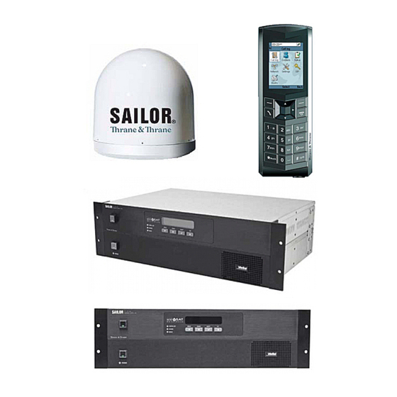
SAILOR 700 VSAT User Manual Chapter 1 - Introduction System Components The SAILOR 700 VSAT system includes the following components: The ADU provides the satellite link between the onboard modem and the land-based hub. Using its integrated GPS, advanced reflector technology, and... - Page 16 Ethernet (PoE). Service Activation Before you can start using the SAILOR 700 VSAT, you need to activate the system for mini-VSAT Broadband service. To activate, simply fill out the Activation Form provided with your system. Then fax the completed form to Thrane & Thrane at the following number: Thrane &...
- Page 17 SAILOR 700 VSAT User Manual Chapter 2 - Operation 2. Operation This chapter explains how to turn on and use the SAILOR 700 VSAT system. It also explains how to interpret the startup screens. Contents Satellite Communication Basics ........11 Turning On the System ............
-
Page 19: Operation
Figure 2-1 Example of a Satellite Footprint Equator In addition, since satellites are located 22,300 miles (35,900 km) above the equator, the SAILOR 700 VSAT ADU must have a clear view of the sky to transmit and receive signals. IMPORTANT! Anything that stands between the ADU and the satellite can block signals, resulting in lost data. -
Page 20: Turning On The System
SAILOR 700 VSAT User Manual Chapter 2 - Operation Turning On the System Follow the steps below to turn on your SAILOR 700 VSAT system. CAUTION The ADU transmits RF energy that is potentially harmful. Everyone must stay more than 36 feet (11 m) away from the ADU within its 5°-80°... -
Page 21: System Startup
SAILOR 700 VSAT User Manual Chapter 2 - Operation System Startup The ACU shows the following screens during startup. If the display shows an error message, see “Error Messages” on page ACU Screen Description The ADU is running a self test routine... -
Page 22: Using The Mini-Vsat Broadband Service
SAILOR 700 VSAT User Manual Chapter 2 - Operation Using the mini-VSAT Broadband Service Once the SAILOR 700 VSAT VMU establishes a connection with the mini-VSAT Broadband service, you can perform all of the same Internet tasks you perform at home: •... -
Page 23: Using The Voip Service
Using the VoIP Service The Thrane & Thrane IP Handset is used for making phone calls over an IP-based network. When used with the SAILOR 700 VSAT system, it allows you to make and receive phone calls using the mini-VSAT Broadband service. - Page 24 Chapter 2 - Operation Placing a Voice Call to the IP Handset To place a call to a Thrane IP handset connected to the SAILOR 700 VSAT system, you need to call a central switchboard, which will put you in contact with the number of the SAILOR 700 VSAT system you wish to call.
-
Page 25: Configuration
It also explains how to configure your computer for a wired Ethernet connection to the SAILOR 700 VSAT system. For details on setting up a wireless network, refer to the instructions provided with your wireless access point (purchased separately). -
Page 27: Adjusting The Acu Display Brightness
SAILOR 700 VSAT User Manual Chapter 3 - Configuration Adjusting the ACU Display Brightness Follow the steps below to adjust the brightness of the ACU’s front panel display. 1. Press MENUS until the display shows “CONFIGURATION.” CONFIGURATION NEXT MENU ACCEPT 2. -
Page 28: Configuring Rf Radiation Hazard Zones
SAILOR 700 VSAT User Manual Chapter 3 - Configuration Configuring RF Radiation Hazard Zones To prevent exposure to the ADU’s radiated RF energy, you can configure up to two RF radiation hazard zones for areas frequented by crew and/or passengers. (See “Important Safety Information”... - Page 29 SAILOR 700 VSAT User Manual Chapter 3 - Configuration Defining an RF Radiation Hazard Zone Follow the steps below to configure an RF radiation hazard zone. 1. Determine the necessary azimuth range for the RF hazard zone. You will need to enter the beginning and ending azimuths that define the outer boundaries of the zone, relative to the ADU’s forward arrow, which...
- Page 30 SAILOR 700 VSAT User Manual Chapter 3 - Configuration 4. Press MENUS until the display shows “SET HAZARD ZONE.” SET HAZARD ZONE= NO NEXT ITEM CHANGE 5. Press CHANGE until the display shows “SET HAZARD ZONE = YES.” SET HAZARD ZONE=YES?
- Page 31 SAILOR 700 VSAT User Manual Chapter 3 - Configuration ZONE 1= 300-000 CHANGE ACCEPT 10. Repeat steps 8 and 9 to set the remaining digits of the range of azimuths for zone #1. Once you have set the entire range, the cursor disappears from the display.
- Page 32 SAILOR 700 VSAT User Manual Chapter 3 - Configuration 13. If the display shows “XMT IN ZONES = YES,” press CHANGE until the display shows “XMT IN ZONES = NO.” Then press ACCEPT. XMT IN ZONES= NO? CHANGE ACCEPT 14. Press EXIT to exit the menu.
- Page 33 SAILOR 700 VSAT User Manual Chapter 3 - Configuration Disabling RF Radiation Hazard Zones If you wish to remove all restrictions on transmissions, follow the steps below to disable your programmed RF radiation hazard zones. This function simply disables the hazard zones; it does not delete them from memory.
- Page 34 SAILOR 700 VSAT User Manual Chapter 3 - Configuration SET HAZARD ZONE=YES? CHANGE ACCEPT 5. Press ACCEPT. ZONE 1= 335-025 NEXT ITEM CHANGE 6. Press MENUS until the display shows “XMT IN ZONES.” XMT IN ZONES= NO NEXT ITEM CHANGE Press CHANGE until the display shows “XMT IN ZONES = YES.”...
-
Page 35: Setting Dvb-Assist Search Mode On/Off
Setting DVB-Assist Search Mode On/Off In most conditions, you should keep the DVB-Assist search mode turned on. With DVB-Assist enabled, the SAILOR 700 VSAT ADU finds a DVB-Assist satellite first before it shifts to point at the mini-VSAT Broadband service satellite. This process speeds up the system startup time, since the ADU normally finds the service satellite much faster when using the DVB-Assist satellite as a guidepost. - Page 36 SAILOR 700 VSAT User Manual Chapter 3 - Configuration 4. Press CHANGE until the display shows the desired DVB-Assist setting: ON or OFF. DVB ASSIST= OFF? CHANGE ACCEPT 5. Press ACCEPT.
-
Page 37: Resetting The System To Factory Conditions
SAILOR 700 VSAT User Manual Chapter 3 - Configuration Resetting the System to Factory Conditions Follow the steps below to reset the SAILOR 700 VSAT system to its original factory configuration. CAUTION Resetting the system clears all RF radiation hazard zones. The ADU will be able to transmit in any direction until you reprogram the hazard zones into the ADU. - Page 38 SAILOR 700 VSAT User Manual Chapter 3 - Configuration 4. Press CHANGE until the display shows “FACTORY RESET= YES.” FACTORY RESET= YES? CHANGE ACCEPT 5. Press ACCEPT. RESET TO FACTORY? ACCEPT EXIT 6. Press ACCEPT again to reset the system.
-
Page 39: Configuring Your Computer For Mini-Vsat Broadband
SAILOR 700 VSAT User Manual Chapter 3 - Configuration Configuring Your Computer for mini-VSAT Broadband Follow the steps below to configure your computer for DHCP addressing. This will allow your computer to communicate with the VMU via its Ethernet connection. - Page 40 SAILOR 700 VSAT User Manual Chapter 3 - Configuration Windows Vista Follow the steps below to configure a Windows Vista computer. 1. At the Windows Control Panel, double-click the Network and Sharing Center icon. You can find the Control Panel either through the Start menu or “My Computer.”...
- Page 41 SAILOR 700 VSAT User Manual Chapter 3 - Configuration 4. At the Local Area Connection Properties window, select the Networking tab. Then select Internet Protocol Version 4 and click Properties. 5. At the Internet Protocol Properties window, select Obtain an IP address...
- Page 42 SAILOR 700 VSAT User Manual Chapter 3 - Configuration 6. At Local Area Connection Properties, click OK.
- Page 43 SAILOR 700 VSAT User Manual Chapter 3 - Configuration Windows XP Follow the steps below to configure a Windows XP computer. 1. At the Windows Control Panel, double-click the Network Connections icon. You can find the Control Panel either through the Start menu or “My Computer.”...
- Page 44 SAILOR 700 VSAT User Manual Chapter 3 - Configuration 4. At the Local Area Connection Properties window, select the General tab. Then select Internet Protocol (TCP/IP) and click Properties. 5. At the Internet Protocol (TCP/IP) Properties window, select the General tab.
- Page 45 SAILOR 700 VSAT User Manual Chapter 3 - Configuration 6. At Local Area Connection Properties, click OK. Restart your computer.
- Page 46 SAILOR 700 VSAT User Manual Chapter 3 - Configuration Mac OS X Follow the steps below to configure a Mac OS X computer. 1. At System Preferences, click the Network icon. 2. At the Network window, select the following: Show: Built-in Ethernet •...
-
Page 47: Configuring The Thrane Ip Handset For Sailor 700
SAILOR 700 VSAT User Manual Chapter 3 - Configuration Configuring the Thrane IP Handset for SAILOR 700 The following section explains how to configure the Thrane IP handset with the SAILOR 700 VoIP account information and codec. The SAILOR 700 VoIP account information is supplied by the Thrane & Thrane distributor who installed the SAILOR 700 system. - Page 48 SAILOR 700 VSAT User Manual Chapter 3 - Configuration 2. Enter following under the SIP settings: • Profile name, e.g. SAILOR, • Server name / IP: sipproxy.thrane.com • Username (supplied by the distributor) • Password (supplied by the distributor) • Set Codec Priority to G729.
-
Page 49: Troubleshooting
SAILOR 700 VSAT User Manual Chapter 4 - Troubleshooting 4. Troubleshooting This chapter identifies basic problems along with their possible causes and solutions. It also explains what the status lights indicate, how to use the diagnostic functions, and how to get technical support. -
Page 51: Five Simple Checks
Chapter 4 - Troubleshooting Five Simple Checks If you are experiencing a problem with your SAILOR 700 VSAT system, first check the five simple things below. If these checks do not lead you to the problem, contact a Thrane & Thrane-authorized technician (see “Technical Support”... -
Page 52: Control Unit (Acu) Status Lights
SAILOR 700 VSAT User Manual Chapter 4 - Troubleshooting Control Unit (ACU) Status Lights Three status lights on the front of the ACU indicate the current status of the system and can help you identify problems quickly. Figure 4-1 Control Unit Status Lights During normal operation, all three status lights should be lit green. - Page 53 SAILOR 700 VSAT User Manual Chapter 4 - Troubleshooting ANTENNA Light The table below explains what the ANTENNA light indicates. Light is... Indicates Description No power input to the ADU Green Tracking ADU is tracking the satellite Green, Searching ADU is searching for the satellite...
-
Page 54: Modem (Vmu) Status Light
SAILOR 700 VSAT User Manual Chapter 4 - Troubleshooting Modem (VMU) Status Light A status light on the front of the VMU indicates the current status of the VMU and can help you identify problems. Figure 4-2 VMU Status Light During normal operation, the status light should be lit green. -
Page 55: Error Messages
SAILOR 700 VSAT User Manual Chapter 4 - Troubleshooting Error Messages The table below lists error messages that might appear on the ACU display to indicate a system problem. Many of these faults should only be repaired by a Thrane & Thrane-authorized technician. For details on finding a Thrane & Thrane- authorized technician, see “Technical Support”... - Page 56 SAILOR 700 VSAT User Manual Chapter 4 - Troubleshooting Error Message Description The ACU is not supplying enough power ERROR: to the ADU. Contact a Thrane & Thrane- CTRL UNIT PWR SUPPLY authorized technician. The ADU’s power supply circuit might ERROR: have failed.
- Page 57 SAILOR 700 VSAT User Manual Chapter 4 - Troubleshooting Error Message Description The ACU has lost communications with ERROR: the VMU. Ensure the VMU is powered on MODEM COMM FAILURE and check the interconnecting cables. You can also try turning the VMU off, then back on.
-
Page 58: Troubleshooting A Voip Service Problem
DHCP enabled. (Select Network > Settings and check the IP address) • Check that the SAILOR 700 VSAT system is online on the Internet by sending a ping command from the DOS command prompt to a known IP address, such as 4.2.2.1, which is a DNS server that answers to ping commands. - Page 59 SAILOR 700 VSAT User Manual Chapter 4 - Troubleshooting Problem Remedies The handset display shows the • Check that a new SAILOR SIP profile for the SAILOR 700 VoIP following error message: service is created and selected instead of the BGAN profile.
-
Page 60: Viewing Status Information On Your Web Browser
SAILOR 700 VSAT User Manual Chapter 4 - Troubleshooting Viewing Status Information on Your Web Browser Complete system status information is available via the VMU’s local web interface. Simply open the web browser on any networked computer and enter the following web address: http://192.168.0.1... - Page 61 SAILOR 700 VSAT User Manual Chapter 4 - Troubleshooting The System Status page provides the following information: Status Message Description • Online - VMU is connected to the MBS System Status mini-VSAT Broadband service • Offline - VMU is not connected to the...
- Page 62 SAILOR 700 VSAT User Manual Chapter 4 - Troubleshooting Detailed Antenna Status When you click the link for “detailed antenna status,” the following web page is displayed. Figure 4-4 Detailed Antenna Status Page...
- Page 63 SAILOR 700 VSAT User Manual Chapter 4 - Troubleshooting The Detailed Antenna Status page provides the following information: Status Message Description Antenna Model TracPhone V7 (SAILOR 700 VSAT) Antenna State Same as System Status page Satellite Location Same as System Status page...
- Page 64 SAILOR 700 VSAT User Manual Chapter 4 - Troubleshooting Detailed Modem Status When you click the link for “detailed modem status,” the following web page is displayed. Figure 4-5 Detailed Modem Status Page...
- Page 65 SAILOR 700 VSAT User Manual Chapter 4 - Troubleshooting The Detailed Modem Status page provides the following information: Status Message Description Serial Number VMU serial number Modem Satellite IP External IP address of the VMU; identity of the VMU on mini-VSAT Broadband...
-
Page 66: Viewing Status Information On The Acu
SAILOR 700 VSAT User Manual Chapter 4 - Troubleshooting Viewing Status Information on the ACU If you are unable to view the status information screens on the VMU’s web interface, you can also view system status information on the ACU’s display. You can select either modem or antenna status information from the main menu. - Page 67 SAILOR 700 VSAT User Manual Chapter 4 - Troubleshooting Modem Status Messages The table below lists all of the modem status messages. Status Message Description General status of the VMU: MODEM STATE • Online - VMU is connected to the...
- Page 68 SAILOR 700 VSAT User Manual Chapter 4 - Troubleshooting Status Message Description Subnet mask of the vessel’s LAN that is MODEM SUBNET MASK connected to the VMU 255.255.255.0 Status of the VMU’s DHCP server: MODEM DHCP STATUS • Enabled - VMU is assigning IP...
- Page 69 SAILOR 700 VSAT User Manual Chapter 4 - Troubleshooting Antenna Status Information 1. Press MENUS until the display shows “ANTENNA STATUS.” ANTENNA STATUS NEXT MENU ACCEPT 2. Press ACCEPT to start viewing the antenna status screens. PRESS TO VIEW EACH ANTENNA ITEM...
- Page 70 SAILOR 700 VSAT User Manual Chapter 4 - Troubleshooting Antenna Status Messages The table below lists all of the status messages. Status Message Description General status of the ADU: ANTENNA STATE • Tracking TRACKING • Searching • Initializing • Waiting for Modem •...
- Page 71 SAILOR 700 VSAT User Manual Chapter 4 - Troubleshooting Status Message Description DC voltage measured at the ADU’s ANTENNA DC INPUT circuit board 41.2 VDC DC voltage measured at the ACU’s CTRL UNIT DC INPUT power input 13.4 VDC Status of the ADU’s BUC (transmit)
-
Page 72: Calibrating The Adu Gyros
Chapter 4 - Troubleshooting Calibrating the ADU Gyros The SAILOR 700 VSAT ADU’s gyros continuously measure the motion of your vessel and send this data to the ADU’s motor control circuitry to keep the ADU pointed at the satellite. At the factory, each ADU gyro is precisely calibrated to work with the ADU’s circuit board. - Page 73 SAILOR 700 VSAT User Manual Chapter 4 - Troubleshooting 4. Press ACCEPT to start gyro calibration. DO NOT MOVE VESSEL DURING CALIBRATION CALIBRATING GYROS SKEW: 5. Verify that the azimuth (AZ), elevation (EL), and skew gyros all pass (“P”). If any gyro fails (“F”), retry the calibration. If it continues to fail, please seek technical support (see “Technical Support”...
-
Page 74: Technical Support
Therefore, if you experience an operating problem or require technical assistance, please call or visit your local authorized SAILOR 700 VSAT dealer or distributor. You can find a distributor near you by visiting www.thrane.com/contact/distributors.aspx. -
Page 75: Wiring Diagram
SAILOR 700 VSAT User Manual Appendix A - Wiring Diagram Appendix A Wiring Diagram This appendix provides a system wiring diagram. For detailed installation instructions, refer to the Installation Guide. Contents Wiring Diagram ...............69... -
Page 77: Wiring Diagram
SAILOR 700 VSAT User Manual Appendix A - Wiring Diagram Wiring Diagram Thrane IP Handset... -
Page 79: Menus Quick Reference Guide
SAILOR 700 VSAT User Manual Appendix B - Menus Quick Reference Guide Appendix B Menus Quick Reference Guide This appendix provides a quick reference guide to the ACU menus. Contents Menus Quick Reference Guide.........75... -
Page 81: Menus Quick Reference Guide
SAILOR 700 VSAT User Manual Appendix B - Menus Quick Reference Guide Menus Quick Reference Guide... -
Page 83: Glossary
SAILOR 700 VSAT User Manual Appendix C - Glossary Appendix C Glossary This appendix provides a glossary of technical terms used throughout this manual. Contents Glossary ................77... -
Page 85: Glossary
SAILOR 700 VSAT User Manual Appendix C - Glossary Glossary 10BaseT Ethernet standard using twisted pair cabling (such as CAT5). Supports a maximum data rate of 10 Mbps. 100BaseT Fast Ethernet standard using twisted pair cabling (such as CAT5). Supports a maximum data rate of 100 Mbps. - Page 86 SAILOR 700 VSAT User Manual Appendix C - Glossary CAT5 Category of twisted pair cable with a maximum data rate of 1,000 Mbps. Chassis The outside enclosure of an electronic device. Crossover Cable Cable in which the pins are reversed from one end to the other. Used for connecting two computers back-to-back without using an Ethernet hub.
- Page 87 SAILOR 700 VSAT User Manual Appendix C - Glossary Eb/No Ratio of Energy-per-bit to Noise power spectral density. The signal-to-noise ratio of a digital signal. EIRP Effective Isotropic Radiated Power, measured in dBW. Elevation angle. Vertical direction (5°-80°) in which the ADU points.
- Page 88 HyperText Transfer Protocol. The primary protocol for the World Wide Web. Earth station that links the satellite network to the terrestrial network. Intermediate Frequency. As it applies to SAILOR 700 VSAT, L-band output of an LNB, or input to a BUC.
- Page 89 SAILOR 700 VSAT User Manual Appendix C - Glossary Low Noise Block down-converter. Device that converts and amplifies a Ku-band satellite signal into an intermediate frequency (IF) L-band signal. MAC Address Media Access Control Address. Unique six-byte hardware identifier assigned to every network interface card (NIC).
- Page 90 SAILOR 700 VSAT User Manual Appendix C - Glossary PCMCIA Personal Computer Memory Card International Association. Organization that establishes standards for PC cards, credit card-sized memory or input/output devices, primarily used in laptops. Ping Software utility used to check a network connection. Sends a test packet to the designated address and reports how long it takes to receive a response.
- Page 91 SAILOR 700 VSAT User Manual Appendix C - Glossary Spread Spectrum A type of communication method by which the information signal energy is spread over a frequency band much wider than the minimum bandwidth required for transmitting the information. SSID Service Set Identifier.
- Page 92 SAILOR 700 VSAT User Manual Appendix C - Glossary Twisted Pair Cable type consisting of multiple pairs of cable in which two wires are spiraled together to reduce electromagnetic noise. Can be either shielded (STP) or unshielded (UTP). Used extensively in LANs and telephone networks.
- Page 93 SAILOR 700 VSAT User Manual Appendix C - Glossary Wireless Network Access Point. Device that links computers wirelessly to a LAN. To communicate with the WAP, each computer needs a properly configured wireless network card. Wired Equivalent Privacy. Security mechanism for wireless networks. Encrypts data to protect it from unauthorized interception.
- Page 94 TT-98-128893-THR-D Thrane & Thrane A/S info@thrane.com www.thrane.com • •...
Need help?
Do you have a question about the SAILOR 700 VSAT and is the answer not in the manual?
Questions and answers