Table of Contents
Advertisement
Naza-M (V2)
Quick Start Guide
V 1.14
2013.07.23 Revision
For Firmware Version V3.12 or above
Version
& Assistant Software
V2.12 or above
Thank you for purchasing this DJI product. Please strictly follow these steps to mount and connect this system on
your aircraft, as well as to install the Assistant Software on your computer.
*
www.dji-innovations.com
Please regularly check the web page of corresponding product
at our website
,
which is updated regularly. Product information, technical updates and manual corrections will be available on this
web page. Due to unforeseen changes or product upgrades, the information contained in this manual is subject to
change without notice.
*
Important: Naza-M, Naza-M V2 and PHANTOM control system are different in hardware parts, but their
configurations and functions are the same when using the same Assistant Software and Firmware Version, so they
use the same Guide. Unless stated, the following instruction is basic on Naza-M V2. If you use the Naza-M, please
make sure to read the "Instruction of V1 (also known as Naza-M)" section; if you use the PHANTOM, download the
other corresponding manuals on the PHANTOM web page.
This manual is only for basic assembly and configuration; you can obtain more details and advanced instructions
when using the assistant software. To assure you have the latest information, please visit our website and download
the latest manual and current software version.
If you have any problem that you cannot solve during usage, please contact your authorized dealer.
©2013 DJI Innovations. All Rights Reserved.
Advertisement
Table of Contents

Related Manuals for dji Naza-M V2


Summary of Contents for dji Naza-M V2
- Page 1 Assistant Software and Firmware Version, so they use the same Guide. Unless stated, the following instruction is basic on Naza-M V2. If you use the Naza-M, please make sure to read the “Instruction of V1 (also known as Naza-M)” section; if you use the PHANTOM, download the other corresponding manuals on the PHANTOM web page.
-
Page 2: Table Of Contents
HOULD YOU FIND THE MULTI ROTOR DOES NOT TRACK STRAIGHT IN FORWARD FLIGHT ..............28 OTORS TART FAILURE CAUSED BY STICK MID POINT ERROR TOO BIG ................. 29 TTITUDE ONTROLLABLE OTOR UTPUT IS AILED ©2013 DJI Innovations. All Rights Reserved. -
Page 3: Instruction
Make sure all connections are good, and keep children and animals away during firmware upgrade, system calibration and parameter setup. DJI Innovations accepts no liability for damage(s) or injuries incurred directly or indirectly from the use of this product in the following conditions: Damage(s) or injuries incurred when users are drunk, taking drugs, drug anesthesia, dizziness, fatigue, nausea and any other conditions no matter physically or mentally that could impair your ability. -
Page 4: Trademark
This product and manual are copyrighted by DJI Innovations with all rights reserved. No part of this product or manual shall be reproduced in any form without the prior written consent or authorization of DJI Innovations. No patent liability is assumed with respect to the use of the product or information contained herein. -
Page 5: Assembly & Connection
Controller EXP port Connect to Main Controller LED port Micro-USB: PC connection for parameter configuration and firmware upgrade Pointing to the aircraft nose direction Connect to GPS port of PMU GPS/Compass *ESC: Electronic Speed Controller ©2013 DJI Innovations. All Rights Reserved. -
Page 6: Step2 Assembly & Connection
Please use the ESCs and motors recommended by the manufacturer NOT mount the MC upside-down. (2)The MC sides of your aircraft. We recommend you use DJI motors and ESCs (Refer should be parallel to the aircraft body. (3)The arrow to its manual for details). Connect all ESCs to MC by the motor should point to the nose direction of aircraft. -
Page 7: Assistant Software Installation And Configuration
Assistant Software Installation and Configuration Step1 Software and Driver Installation on a PC Please download the drive installer and the assistant software installer from DJI website “www.dji-innovations.com”, by selecting the Download web page of corresponding product. Switch on the transmitter first, and then power on the autopilot system. - Page 8 Attitude Gain Motor Propeller Battery Weight Pitch Roll Vertical Pitch Roll F330 DJI-2212 DJI-18A DJI-8 Inch 3S-2200 790 g F450 DJI-2212 DJI-30A DJI-8 Inch 3S-2200 890 g F550 DJI-2212 DJI-30A DJI-8 Inch 4S-3300 1530 g ©2013 DJI Innovations. All Rights Reserved.
-
Page 9: Basic Flying
Please get to know well about this section before flying. Start Motor: Pushing throttle stick before takeoff will not start the motors. You have to execute any one of following four Combination Stick Commands (CSC) to start the motors: ©2013 DJI Innovations. All Rights Reserved. - Page 10 In any control mode, DO NOT pull throttle stick under 10% during normal flight without any reason. Any of these two cut off types will only work properly if TX calibration is correct done. In failed-safe, CSC is denied by the main controller, motors will hold their state. ©2013 DJI Innovations. All Rights Reserved.
-
Page 11: Step 1 Compass Calibration
If the flight direction appears to be shifting (meaning the multi-rotor doesn’t “fly straight”). The LED indicator often indicates abnormality blinking when the multi-rotor spins. (It is normal for this to happen only occasionally) ©2013 DJI Innovations. All Rights Reserved. -
Page 12: Step 2 Assembly Checking List
Signal is well (GPS satellites = 6) : ATTI. Mode: indicates that is stick(s) not at center) Signal is bad(GPS satellites = 5) : GPS Mode: indicates that is stick(s) not at center) Signal is worst (GPS satellites< 5) : ©2013 DJI Innovations. All Rights Reserved. -
Page 13: Step 4 Flying Test
Lower the aircraft slowly. Pull the throttle stick to the bottom and then execute the CSC to stop the motors after landing. Please always power off the Multi-rotor first, and then switch off the transmitter after landing. ©2013 DJI Innovations. All Rights Reserved. - Page 14 Software once Low-Voltage Alarm is triggered. Make sure you remember what you have set before. If Fail-Safe function is set, the aircraft will act according to the configuration of the Assistant Software once Fail-Safe is triggered. Make sure you remember what you have set before. ©2013 DJI Innovations. All Rights Reserved.
-
Page 15: Advanced Functions
TX, because the aircraft will take off automatically, so do not try this. If signal lost for more than 3 seconds failsafe will be triggered, if signal regained within 3 seconds it will exit failsafe immediately. ©2013 DJI Innovations. All Rights Reserved. -
Page 16: A2 Low -Voltage Alert
Configure the FailSafe function in the assistant software -> “Advanced” -> “F/S” and read the instruction thoroughly and carefully. Configure the Low-Voltage Alert function in the assistant software -> “Advanced” -> “Voltage” and read the instruction thoroughly and carefully. ©2013 DJI Innovations. All Rights Reserved. - Page 17 The above table is for example. The function of the switch position may be reversed since the normal/reversed setting of the switch channel. Toggle the switch and observe the slider position of channel X2 on the assistant software screen, the corresponding area should turn blue. ©2013 DJI Innovations. All Rights Reserved.
- Page 18 OFF position Lock position to Home Lock position Aircraft moving direction when pull pitch stick Aircraft moving direction when pull roll stick Home point Aircraft(the arrow is pointing to the direction of the aircraft nose) ©2013 DJI Innovations. All Rights Reserved.
- Page 19 We suggest that you should know clearly which flight lock method you are going to fly, and you know the locked forward direction or home point, before you switch on IOC mode during the flight. ©2013 DJI Innovations. All Rights Reserved.
-
Page 20: A4 Receiver Advanced Protection Function
Mode and Manual Mode, it will quit the FailSafe Mode automatically. In GPS Mode, please toggle the control mode switch to the ATTI. Mode and Manual Mode position to regain the control. Refer to the FailSafe section for more details. ©2013 DJI Innovations. All Rights Reserved. -
Page 21: Appendix
(can be effected by mechanical performance and payloads) Hovering Accuracy (GPS Mode) Vertical: ±± 0.8m Horizontal: ±±2.5m Max Yaw Angular Velocity 200°/s Max Tilt Angle 35° Max Ascent / Descent Speed ±Ascent : 6m/s, Descent: 4.5 m/s ©2013 DJI Innovations. All Rights Reserved. -
Page 22: Mc/Pmu Firmware Upgrade
Select Upgrade optionCheck the MC and PMU Firmware Version. DJI server will check your current firmware version, and get the latest firmware prepared for the unit. If there is a firmware version more up-to-date than your current version, you will be able to click to update them. -
Page 23: Led Description
GPS Signal is Worst (GPS Satellite number < 5): Compass Calibration LED Flashing Begin horizontal calibration Begin vertical calibration Calibration or others error *You can figure out the error by connecting the autopilot system to the assistant software. ©2013 DJI Innovations. All Rights Reserved. -
Page 24: Instruction Of V1 (Also Known As Naza-M)
· The DJI logo marked on the GPS should face the sky, with the orientation arrow pointing directly · In three-pin ports, pins near the nicks are signal pins. forward. The GPS/Compass is packaged with a special indication line for mounting for the first time. -
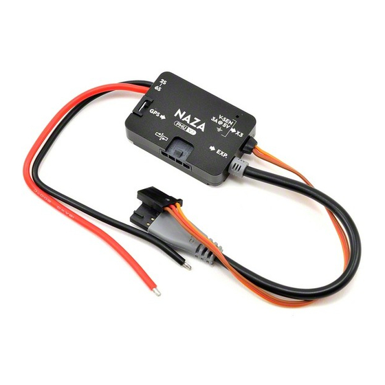
Page 25: V1 Port Description
Red wire (power wire) output: 3A@5V LED wire, to LED port of the main controller. USB port: PC connection for configuration and firmware upgrades. Optional GPS & Compass Connect to the EXP. port. ©2013 DJI Innovations. All Rights Reserved. -
Page 26: V1 Specification
(can be effected by mechanical performance and payloads) Hovering Accuracy (GPS Mode) Vertical: ±± 0.8m Horizontal: ±± 2.5m Max Yaw Angular Velocity 200°/s Max Tilt Angle 45° Max Ascent / Descent Speed ±6m/s ©2013 DJI Innovations. All Rights Reserved. -
Page 27: Faq
When flying in GPS ATTI. Mode and the compass calibration has been done correctly, should you find the aircraft rotating (Toilet bowl effect), or drifting when hovering. Please check the GPS module mounting orientation and then ©2013 DJI Innovations. All Rights Reserved. -
Page 28: Should You Find The Multi-Rotor Does Not Track Straight In Forward Flight
Adjust the largest travel of TX stick until the cursor on the Assistant software can reach both end positions, according to your TX manual. Power cycle the autopilot system, note that power cycle is required. Redo the TX calibration according to the Assistant software. ©2013 DJI Innovations. All Rights Reserved. -
Page 29: Attitude Controllable When One Motor Output Is Failed
Select Course lock or home lock mode for flying the aircraft into a safe area to land when the aircraft is far away or the attitude can’t be recognized. Even when the multi rotor is rotating, using Course lock or home lock mode will allow you to move the multi rotor in the corresponding Transmitter stick direction. ©2013 DJI Innovations. All Rights Reserved.
Need help?
Do you have a question about the Naza-M V2 and is the answer not in the manual?
Questions and answers